WO2012140730A1 - Système de gestion, système informatique doté de celui-ci et procédé de gestion - Google Patents
Système de gestion, système informatique doté de celui-ci et procédé de gestion Download PDFInfo
- Publication number
- WO2012140730A1 WO2012140730A1 PCT/JP2011/059064 JP2011059064W WO2012140730A1 WO 2012140730 A1 WO2012140730 A1 WO 2012140730A1 JP 2011059064 W JP2011059064 W JP 2011059064W WO 2012140730 A1 WO2012140730 A1 WO 2012140730A1
- Authority
- WO
- WIPO (PCT)
- Prior art keywords
- information
- logical volume
- storage
- virtual
- storage device
- Prior art date
- Legal status (The legal status is an assumption and is not a legal conclusion. Google has not performed a legal analysis and makes no representation as to the accuracy of the status listed.)
- Ceased
Links
Images





Classifications
-
- G—PHYSICS
- G06—COMPUTING OR CALCULATING; COUNTING
- G06F—ELECTRIC DIGITAL DATA PROCESSING
- G06F3/00—Input arrangements for transferring data to be processed into a form capable of being handled by the computer; Output arrangements for transferring data from processing unit to output unit, e.g. interface arrangements
- G06F3/06—Digital input from, or digital output to, record carriers, e.g. RAID, emulated record carriers or networked record carriers
- G06F3/0601—Interfaces specially adapted for storage systems
- G06F3/0628—Interfaces specially adapted for storage systems making use of a particular technique
- G06F3/0629—Configuration or reconfiguration of storage systems
- G06F3/0632—Configuration or reconfiguration of storage systems by initialisation or re-initialisation of storage systems
-
- G—PHYSICS
- G06—COMPUTING OR CALCULATING; COUNTING
- G06F—ELECTRIC DIGITAL DATA PROCESSING
- G06F3/00—Input arrangements for transferring data to be processed into a form capable of being handled by the computer; Output arrangements for transferring data from processing unit to output unit, e.g. interface arrangements
- G06F3/06—Digital input from, or digital output to, record carriers, e.g. RAID, emulated record carriers or networked record carriers
- G06F3/0601—Interfaces specially adapted for storage systems
- G06F3/0602—Interfaces specially adapted for storage systems specifically adapted to achieve a particular effect
- G06F3/061—Improving I/O performance
-
- G—PHYSICS
- G06—COMPUTING OR CALCULATING; COUNTING
- G06F—ELECTRIC DIGITAL DATA PROCESSING
- G06F3/00—Input arrangements for transferring data to be processed into a form capable of being handled by the computer; Output arrangements for transferring data from processing unit to output unit, e.g. interface arrangements
- G06F3/06—Digital input from, or digital output to, record carriers, e.g. RAID, emulated record carriers or networked record carriers
- G06F3/0601—Interfaces specially adapted for storage systems
- G06F3/0628—Interfaces specially adapted for storage systems making use of a particular technique
- G06F3/0662—Virtualisation aspects
- G06F3/0665—Virtualisation aspects at area level, e.g. provisioning of virtual or logical volumes
-
- G—PHYSICS
- G06—COMPUTING OR CALCULATING; COUNTING
- G06F—ELECTRIC DIGITAL DATA PROCESSING
- G06F3/00—Input arrangements for transferring data to be processed into a form capable of being handled by the computer; Output arrangements for transferring data from processing unit to output unit, e.g. interface arrangements
- G06F3/06—Digital input from, or digital output to, record carriers, e.g. RAID, emulated record carriers or networked record carriers
- G06F3/0601—Interfaces specially adapted for storage systems
- G06F3/0668—Interfaces specially adapted for storage systems adopting a particular infrastructure
- G06F3/067—Distributed or networked storage systems, e.g. storage area networks [SAN], network attached storage [NAS]
-
- G—PHYSICS
- G06—COMPUTING OR CALCULATING; COUNTING
- G06F—ELECTRIC DIGITAL DATA PROCESSING
- G06F11/00—Error detection; Error correction; Monitoring
- G06F11/30—Monitoring
- G06F11/34—Recording or statistical evaluation of computer activity, e.g. of down time, of input/output operation ; Recording or statistical evaluation of user activity, e.g. usability assessment
- G06F11/3409—Recording or statistical evaluation of computer activity, e.g. of down time, of input/output operation ; Recording or statistical evaluation of user activity, e.g. usability assessment for performance assessment
- G06F11/3433—Recording or statistical evaluation of computer activity, e.g. of down time, of input/output operation ; Recording or statistical evaluation of user activity, e.g. usability assessment for performance assessment for load management
-
- H—ELECTRICITY
- H04—ELECTRIC COMMUNICATION TECHNIQUE
- H04L—TRANSMISSION OF DIGITAL INFORMATION, e.g. TELEGRAPHIC COMMUNICATION
- H04L67/00—Network arrangements or protocols for supporting network services or applications
- H04L67/01—Protocols
- H04L67/10—Protocols in which an application is distributed across nodes in the network
- H04L67/1097—Protocols in which an application is distributed across nodes in the network for distributed storage of data in networks, e.g. transport arrangements for network file system [NFS], storage area networks [SAN] or network attached storage [NAS]
Definitions
- the present invention relates to a management system, a computer system having the management system, and a management method.
- the present invention relates to a technique for managing a data storage destination in a computer system to which a plurality of storage apparatuses (also referred to as storage subsystems) are connected.
- Patent Document 1 discloses that when the system load of the storage apparatus exceeds, an I / O request from the host is used as an error response, and the host is made to retry the I / O request. More specifically, in Patent Document 1, when it is predicted that the load of a specific RAID logical unit (hereinafter referred to as a RAID group) is increased, access to the RAID group is suppressed, and the RAID group We are trying to increase usage efficiency.
- a RAID logical unit hereinafter referred to as a RAID group
- the controller storage device in the system predicts the load of the RAID group from the state of the I / O request and response from the externally connected storage device, and suppresses the access to the RAID group that is determined to have a high load. We are trying to increase the efficiency of group use.
- the storage capacity of the externally connected storage device is treated as virtually the same storage device, and the response to the I / O request is considered in consideration of the RAID group load of the external storage device.
- the hardware specification information and performance information of the externally connected storage apparatus are not considered at all when controlling the response to the I / O request. Therefore, the I / O request is not controlled in consideration of the load state of various hardware in the external storage device and the I / O characteristic (also referred to as access pattern) to the storage device.
- the load is biased or data is stored in a device that does not meet the I / O characteristics.
- the storage apparatus returns a response to an I / O request using a plurality of hardware such as a processor, a cache, and a RAID group. For this reason, even if only the load of the RAID group is taken into consideration, it cannot be determined whether the response with the expected performance can be performed with respect to the I / O request unless the load of other hardware is taken into consideration. For example, when read access continues for a short period of time for certain data, the storage apparatus can return a response based on the cache information.
- the storage apparatus can return a very quick response without imposing a load on the RAID group.
- Patent Document 1 it is determined that the load on the RAID group is low because of a quick response. However, the load on the RAID group may actually be high. At this time, since the load on the RAID group is considered low, an I / O request is issued to the RAID group without suppressing the I / O request. As a result, the response performance to this I / O request is deteriorated.
- the present invention has been made in view of such a situation, and provides a technique capable of improving the response performance to an I / O request and enhancing the utilization efficiency of a storage apparatus.
- the present invention provides a plurality of storage subsystems, an information processing apparatus that is connected to the storage subsystem and has a virtual layer for virtually providing information therefrom, and manages them A management system.
- the management system manages the configuration information of the logical volume allocated to the virtual instance managed on the virtual layer of the information processing apparatus and the operation information of the hardware resources included in the sub-storage subsystem on the memory. Then, the management system evaluates the usage efficiency of the virtual instance based on the logical volume configuration information and the hardware resource operation information, and outputs the evaluation result.
- the use efficiency of the storage apparatus can be improved.
- FIG. 1 It is a figure which shows schematic structure of the computer system by the 1st Embodiment of this invention. It is a figure which shows the logical structural example of a storage apparatus. It is a figure which shows the structural example of a RAID group management table. It is a figure which shows the structural example of a volume management table. It is a figure which shows the structural example of a storage pool structure table. It is a figure which shows the structural example of a page structure table. It is a figure which shows the structural example of a performance information table. It is a figure which shows the logical structural example of a management server. It is a figure which shows the structural example of the resource performance table on a management server.
- the embodiment of the present invention may be implemented by software running on a general-purpose computer, or may be implemented by dedicated hardware or a combination of software and hardware.
- each information of the present invention will be described in a “table” format.
- the information does not necessarily have to be expressed in a data structure by a table, such as a data structure such as a list, a DB, a queue, or the like. It may be expressed as Therefore, “table”, “list”, “DB”, “queue”, etc. may be simply referred to as “information” to indicate that they do not depend on the data structure.
- program as a subject (operation subject).
- a program is executed by a processor and a process determined by a memory and a communication port (communication control device). Since it is performed while being used, the description may be made with the processor as the subject.
- the processing disclosed with the program as the subject may be processing performed by a computer such as a management server or an information processing apparatus. Part or all of the program may be realized by dedicated hardware, or may be modularized.
- Various programs may be installed in each computer by a program distribution server or a storage medium.
- a storage pool constructed on a controller storage device is used as a virtual technology for centrally managing storage areas that span a plurality of externally connected storage devices.
- the controller storage device refers to a storage device having a function of handling a plurality of storage devices virtually as the same storage device.
- the externally connected storage device is a storage device connected to the controller storage device and handled as the same storage device.
- a computer system in which the controller storage apparatus treats a plurality of externally connected storage apparatuses as virtually the same storage apparatus can also be referred to as a storage virtualization system.
- the storage pool in this embodiment has a function of creating a virtual volume to a host (host computer) created from a volume allocated from a plurality of externally connected storage devices or a volume of a controller storage device.
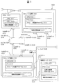
- FIG. 1 is a diagram showing an overall schematic configuration of a computer system according to the first embodiment.
- the computer system 0100 includes a storage device 0101 as a controller storage device, at least one storage device 0102 as an externally connected storage device, a management server (management computer) 0103, at least one host (host computer) 0107, and a SAN. (Storage Area Network) switch 0104.
- the controller storage device 0101 and the host 0107 are connected by a SAN 0145 via a SAN switch 0104.
- the storage apparatuses 0101 and 0102, the management server 0103, and the host 0107 are connected by a LAN (Local Area Network) 0106.
- LAN Local Area Network
- the controller storage device 0101 has a SAN port 0115 and a LAN port 0116, is connected to the SAN 0105 by the SAN port 0115, and is connected to the LAN 0106 by the LAN port 0116.
- the controller storage device 0101 includes a CPU 0111, a memory 0112, and at least one auxiliary storage device 0113.
- the CPU 0111 performs various processes by executing the storage control program 0114 stored in the memory 0112.
- the controller storage device 0101 has a function of making the volume in the externally connected storage device 0102 appear to the host 0107 like a volume provided by itself.
- the memory 0112 stores the storage control program 0114 and information necessary when the CPU 0111 executes the storage control program 0114.
- the storage control program 0114 executes processing for constructing a logical volume that is logically provided from each storage device. Details will be described with reference to FIG.
- the auxiliary storage device 0113 provides an area handled as a storage area by the storage control program 0114 as will be described later.
- the auxiliary storage device 0113 is configured as one in the drawing, but is not limited to one, and may be configured from a plurality of auxiliary storage devices. Examples of the auxiliary storage device 0113 include an FC (Fibre Channel) disk and an SSD (Solid State Drive).
- the controller storage device can also be called a controller storage subsystem.
- the externally connected storage device can also be called an externally connected storage subsystem or simply a storage subsystem.
- Management server 0103 includes a CPU (processor) 0131, a memory 0132, and an auxiliary storage device 0133.
- the management server 0103 has a LAN port 0135 and is connected to the LAN 0106 through the LAN port 0135.
- the CPU 0131 performs various processes by executing the placement destination management program 0134 stored in the memory 0132.
- the memory 0132 stores an arrangement destination management program 0134 and information necessary when the CPU 0131 executes the arrangement destination management program 0134. Details of information and programs in the memory 0132 will be described with reference to FIG.
- the auxiliary storage device 0133 stores information collected and managed by the placement destination management program 0134.
- the placement destination management program 0134 has a function of collecting information from the controller storage device 0101, the externally connected storage device 0102, and the host 0107, and a function of determining and notifying the location of data based on the collected information. Details of the placement destination management program 0134 will be described later.
- the management server 0103 has an input device and a display device (output device), although not shown.
- a serial interface or Ethernet interface is used as the input / output device, and a display computer having a display, keyboard, or pointer device is connected to the interface, and display information is sent to the display computer or input.
- the display computer may perform display, or the input may be replaced by the input / output device by receiving the input.
- a set of one or more computers that manage the storage devices 0101 and 0102 and display the display information of the present invention may be referred to as a management system.
- the management server (management computer) 0103 displays the display information
- the management server 0103 is a management system
- the combination of the management server 0103 and the display computer is also a management system.
- processing equivalent to that of the management server may be realized with a plurality of computers.
- the plurality of computers if the display computer performs display, display (Including computers) is the management system.
- the host 0107 has a CPU 0171 and a memory 0172.
- the host 0107 has a SAN port 0173 and is connected to the SAN 0145 through the SAN port 0144. Further, the host 0107 has a LAN port 0174 and is connected to the LAN 0106 through the LAN port 0174.
- the host 0107 uses the auxiliary storage device 0175 and the volume provided by the storage device 0101 through the SAN 0145 as a storage area.
- the host 0107 is configured. However, the host is not limited to one, and the host 0107 may be configured.
- the SAN switch 0104 is a network device that relays data communication among the controller storage device 0101, the externally connected storage device 0102, and the host 0107, and has SAN ports 0141 to 0144.
- the SAN 0145 in the computer system 0100 is configured by one SAN switch 0104, but is not limited to one, and may be configured by a plurality of SAN switches 0104. Further, each device may be connected by SAN0145 without providing the SAN switch 0104.
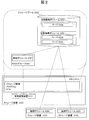
- FIG. 2 is a diagram schematically showing a logical storage area provided by the controller storage device 0101.
- FIG. 2 virtually depicts the role of the controller storage device. With this function, even if a plurality of externally connected storage devices 0102 are installed, the host 0107 recognizes only the controller storage device 0101.
- the details of the logical storage area and the storage control program 0114 will be described first, and then the management information stored in the memory 0112 for managing the logical storage area will be described in detail.
- the storage control program 0114 has a function of constructing a logical storage area from a plurality of auxiliary storage devices (auxiliary storage device 0113 of the controller storage device or auxiliary storage device 0123 of at least one external connection storage device 0102).
- the storage control program 0114 can construct logical storage areas such as a RAID group 0201, a logical volume 0202, a storage pool 0204, and a virtual logical volume 0205.
- a RAID group 0201 a logical volume 0202
- storage pool 0204 a storage pool 0204
- virtual logical volume 0205 virtual logical volume
- the RAID group 0201 is a logical storage area composed of a plurality of auxiliary storage devices 0113, that is, RAID (Redundant Arrays of Inexpensive Disks), and is constructed by the storage control program 0114.
- RAID Redundant Arrays of Inexpensive Disks
- the storage control program 0114 specifies from the auxiliary storage device 0113.
- a RAID group 0201 having a designated RAID level can be constructed. There are various RAID groups, and these can be set together.
- the logical volume 0202 is a logical storage area in the RAID group 0201, and is constructed by the storage control program 0114. For example, when the storage control program 0114 receives the size of the creation source RAID group 0201 and the created logical volume 0202 from the management server 0103 as input values, the storage control program 0114 configures the logical volume 0202 having the designated size from the designated RAID group 0201. can do.
- the storage pool 0204 is a logical storage area composed of a plurality of logical volumes 0202, and is constructed by the storage control program 0114.
- the storage control program 0114 can construct a storage pool 0204 from the specified plurality of logical volumes 0202.
- the storage pool 0204 can be constructed by the logical volume 0203 allocated from the storage apparatus 0102 through the SAN 0145 in addition to the logical volume 0202 on the storage apparatus 0101 in which the storage control program 0114 is stored.
- the page 0206 is one or a plurality of logical storage areas configured from the storage pool 0204, and is constructed by the storage control program 0114.
- the storage control program 0114 receives the size of the page 0206 created from the management server 0103 (variably settable for each page) as an input value, the storage control program 0114 can create the designated page 0206 from the storage pool 0204.
- the data stored in the page 0206 is stored in the logical volume 0202 or the logical volume 0203 constituting the storage pool via the storage pool 0204 constituting the page.
- the virtual logical volume 0205 is a logical storage area constructed from a plurality of pages by the storage control program 0114, and is released to the host 0107 as a virtual volume having a capacity larger than the actual capacity.
- the storage control program 0114 can construct a virtual logical volume 0205 having a capacity specified from a plurality of pages 0206.
- the storage control program 0114 discloses to the host 0107 as a volume having a capacity larger than the actual capacity of the virtual logical volume, and further, one or more pages 0206 are transferred to the virtual logical volume in response to a write command from the host 0107. 0205.
- the storage control program 0114 is a function that configures the logical storage area (logical storage area configuration function), a function that allocates the logical volume 202 and the virtual logical volume 0205 to the host (logical volume allocation function), and a device that allocates the volume.
- a function for allocating page 0206 to virtual logical volume 0205 in response to an I / O instruction (virtual logical volume expansion function), a function for specifying page candidates to be allocated in advance when virtual logical volume is expanded (virtual logical volume expansion policy designation function)
- a function for periodically collecting storage resource performance information (performance information collection function).
- the storage control program 0114 and management information related to these functions are stored in the memory 0112 for management.
- the storage control program 0114 sends management information to each storage device or host in response to a request from the management server 0103.
- a request from the management server 0103 can be requested to the storage control program 0114 via the LAN 0106, for example.
- the storage control program 0114 stores the following five tables in the memory 0112 in order to manage the logical storage area.
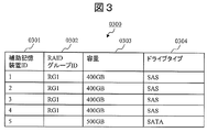
- FIG. 3 is a diagram showing a configuration example of a RAID group management table 0300 that stores information of the RAID group 0201.
- the RAID group management table 0300 includes auxiliary storage device ID 0301, RAID group ID 0302, capacity 0303, and drive type 0304 as configuration items.
- the auxiliary storage device ID 0301 is information for uniquely specifying and identifying the auxiliary storage device 0113 that constitutes the RAID group 0201.
- the RAID group ID 0302 is information for uniquely identifying and identifying the RAID group 0201.
- the capacity 0303 is information indicating the capacity of the auxiliary storage device 0113 constituting the corresponding RAID group 0201.
- the drive type 0304 is information indicating the drive type of the auxiliary storage device 0113 constituting the corresponding RAID group 0201. Drive types include SAS, SATA, and SSD.
- the RAID group ID 0302 is blank.
- the RAID group 1 (RG1) has a capacity of 1600 GB as a whole.
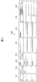
- FIG. 4 is a diagram showing a configuration example of a volume management table 0400 for storing information on the logical volume 0202 and the virtual logical volume 0205.
- the volume management table 0400 includes volume ID 0401, RAID group ID 0402, capacity 0403, storage pool ID 0404, storage port 0405, allocation destination ID 0406, target ID 0407, and virtual logical volume extended logical volume ID 0408 as configuration items. Have as.
- the volume ID 0401 is information for uniquely identifying and identifying the logical volume 0202 or the virtual logical volume 0205.
- the volume from the controller storage device 0101 is indicated by a normal number (for example, “1”), and the volume from the externally connected storage device 0102 is indicated by V1, V2, or the like.
- the RAID group ID 0402 is information for uniquely identifying and identifying the RAID group 0201 that is the generation source of the logical volume 0202 or the virtual logical volume 0205.
- the RAID group ID 0402 is NA.
- the capacity 0403 is information indicating the capacity of the corresponding volume.
- the storage pool ID 0404 is information for uniquely identifying and identifying the storage pool 0204 to which the corresponding volume belongs.
- the storage port 0405 is information for uniquely identifying and identifying the port of the storage device that discloses the corresponding volume.
- the allocation destination ID 0406 is information for uniquely identifying and identifying the volume allocation destination.
- Each WWN World (Wide Name) may be stored as information for uniquely specifying and identifying the port of the storage device and the allocation destination. Further, since the logical volume 1 in FIG. 4 is used for the pool, it is not assigned to the host 0107.
- the target ID 0407 is information indicating information (Target ID) for uniquely identifying and identifying the volume in the access from the volume allocation destination. For example, when a port is virtually divided into a plurality of ports to enable access (see the access path from the host in FIG. 15), it is necessary to identify an access path from a certain device to a predetermined volume.
- the target ID 0407 is information for identifying such an access path.
- the virtual logical volume expansion logical volume ID 0408 is information for uniquely identifying and identifying the logical volume 0202 or the logical volume 0203 used for the virtual logical volume expansion policy designation function. In other words, it is specified from which volume the page is set when expanding the virtual logical volume, and the virtual logical volume extended logical volume ID 0408 is information for specifying the specified logical volume.
- the virtual logical volume expansion policy designation function expands the virtual logical volume 0205
- the page 0206 in the storage area of the logical volume 0202 designated by the virtual logical volume expansion logical volume ID 0408 is transferred to the virtual logical volume 0205. It is a function to assign.
- FIG. 5 is a diagram showing a configuration example of a storage pool configuration table 0500 that stores information on the logical volumes 0202 or 0203 constituting the storage pool 0204.
- the storage pool configuration table 0500 has a storage pool ID 0501, a logical volume ID 0502, a port 0503, and an external connection destination 0504 as configuration items.
- the storage pool ID 0501 is information for uniquely specifying and identifying the storage pool 0204.
- the logical volume ID 0502 is information for uniquely identifying / identifying the logical volume 0202 included in the corresponding storage pool, or information indicating Target ID given when the logical volume 0203 is allocated from the external storage apparatus 0102. It is.
- the storage port 0503 and the external connection destination 0504 are the WWN of the SAN port 0115 to which the logical volume is assigned and the external connection storage device side. This is information indicating the WWN of the SAN port 0125.
- FIG. 6 is a diagram showing a configuration example of the page configuration table 0600 that holds the configuration of the page 0206 and the access history.
- the page configuration table 0600 has a page ID 0601, a virtual logical volume ID 0602, a logical volume ID 0603, and an allocation date and time 0604 as configuration items.
- the page ID 0601 is information for uniquely identifying and identifying the target page 0206.
- the virtual logical volume ID 0602 is information for uniquely identifying and identifying a virtual logical volume that is cut out from the pool 0204 and assigned a corresponding page.
- the logical volume ID 0603 is information for uniquely identifying and identifying the logical volume 0202 or the logical volume 0203 that actually stores the data stored in the corresponding page.
- Allocation date 0604 is information indicating the date and time when the corresponding page is allocated.
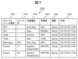
- FIG. 7 is a diagram illustrating a configuration example of the performance information table 0700 that holds the performance values of the resources in the storage apparatus.
- the performance information table 0700 has a storage resource type 0701, a resource ID 0702, a performance type 0703, a performance value 0704, a period 0705, and a date and time 0706 as configuration items.
- the storage resource type 0701 is information for uniquely identifying and identifying the type of the storage resource for which performance is to be managed.
- the resource ID 0702 is information for uniquely identifying and identifying a resource to be managed.
- the performance type 0703 is information for uniquely identifying and identifying the performance type of the managed resource.
- Hit Rate is information indicating how much data can be returned from the cache when an I / O request is received.
- the BusyBRate in the RAID group indicates how long the data read command has been read, that is, how much the head is while the disk device constituting the storage device is rotating. This is information indicating whether data is being read by operating (operation time).
- the Random / Sequential ratio is information indicating the ratio of random access to sequential access (also referred to as I / O characteristics or access pattern) in an I / O request.
- I / O characteristics there is a read / write ratio indicating the ratio of the read request and the write request in the I / O request.
- the performance value 0704 is information indicating the performance of the corresponding resource. 80% / 20% in the Random / Sequential ratio indicates that the ratio of random access is 80% and the ratio of sequential access is 20%.
- the CPU specifications are fixed values unless the CPU itself is changed.
- the period 0705 is information indicating a unit of a period in which the performance of the corresponding resource is measured.
- the unit of period represents, for example, every hour, every day, every week, etc., and may be a total period or a measurement cycle.
- “hourly” means that, for example, an average of a plurality of measured values in a period of one hour is taken (in the case of an aggregation period).
- Date / time 0706 is information indicating the end date / time of the unit of the measurement period.
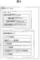
- FIG. 8 is a diagram illustrating a logical configuration example on the memory 0132 and the auxiliary storage device 0133 of the management server 0103.
- the placement destination management program 0801 stored in the memory 0132 includes an information collection program 0811, a placement destination optimization program 0812, and a placement destination information input / output program 0813.
- the auxiliary storage device 0133 stores a resource performance table, a logical volume management table, a path management table, a pool management table, a virtual logical volume management table, and a port management table managed by the placement destination management program 0801.
- FIG. 9 is a diagram illustrating a configuration example of a resource performance table 0900 that manages performance information of resources of each device collected by the information collection program 0811.
- the resource performance table 0900 has device ID 0901, resource type 0902, resource ID 0903, performance type 0904, and performance value 0905 as configuration items.
- the device ID 0901 is information for uniquely identifying and identifying the device from which the information collection program 0811 has collected performance information.
- the resource type 0902 is information for identifying the resource type in the device.
- the resource ID 0903 is information for identifying a resource in the resource type of the device.
- the performance type column 0904 is information indicating the type of the acquired performance information.
- the performance value 0905 is information indicating the performance value of the corresponding resource.
- the values stored in the resource performance table 0900 include, for example, the CPU Busy ⁇ ⁇ Rate and Spec, Cache Hit Rate and Spec, the Busy Rate of the disk constituting the RAID group, and the ratio of random access to sequential access to the volume. is there.
- the ratio of random access is high, the remaining capacity of the cache is not so important for improving the use efficiency and increasing the access speed.
- use efficiency can be increased and access speed can be increased when the remaining capacity of the cache is larger.
- the information stored in the resource performance table 0900 is not limited to the example shown in FIG. 9, but may be information such as ports existing in the storage apparatus.
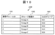
- FIG. 10 is a diagram showing a configuration example of the logical volume management table 1000 for managing the logical configuration of the logical volume collected by the information collection program 0811 from the controller storage device 0101 and the externally connected storage device 0102.
- the logical volume management table 1000 includes a logical volume ID 1001, a storage device ID 1002, and a RAID group ID 1003 as configuration items.
- the logical volume ID 1001 is information for uniquely identifying and identifying a logical volume to be managed.
- the storage apparatus ID 1002 is information for uniquely identifying and identifying the storage apparatus that provides the corresponding logical volume.
- the RAID group ID 1003 is information for uniquely identifying and identifying the RAID group that provides the corresponding logical volume.
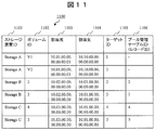
- FIG. 11 is a diagram illustrating a configuration example of the path management table 1100.
- the path management table 1100 manages information indicating the path to which the logical volumes 0202 and 0203 or the virtual logical volume 0205 are disclosed (information indicating the path through which the volume is disclosed). Each piece of information in the table is collected from the controller storage device 0101 and the externally connected storage device 0102 by the information collection program 0811.
- the path management table 1100 includes a storage device ID 1101, a volume ID 1102, an allocation source 1103, an allocation destination 1104, a target ID 1105, and a pool management table ID (record ID) 1106 as configuration items.
- Storage device ID 1101 is information for uniquely specifying and identifying a storage device that provides a public logical volume.
- the volume ID 1102 is information for uniquely identifying and identifying a published volume.
- Allocation source 1103 is WWN information indicating from which SAN port of the storage apparatus the volume is disclosed.
- the allocation destination 1104 is WWN information indicating the disclosure destination of the corresponding logical volume.
- the target ID 1105 stores information that is commonly used to identify the volume disclosed by the same route between the allocation source device and the allocation destination device. As described above, for example, there are two paths from the port of the host A to the port of the storage apparatus A in FIG. 15 to be described later, and the target ID identifies these paths.
- the pool management table ID (record ID) 1106 is information corresponding to the value of the record ID 1206 of the pool management table 1200 described later. This information is input when the storage pool is configured by the logical volume assigned from the externally connected storage device 0102.
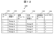
- FIG. 12 is a diagram illustrating a configuration example of the pool management table 1200.
- the pool management table 1200 manages the configuration information of the storage pool 0204 collected by the information collection program 0811 from the controller storage device 0101 and the externally connected storage device 0102.
- the pool management table 1200 includes a pool ID 1201, a storage device ID 1202, a logical volume ID 1203, an externally connected storage device ID 1204, an external logical volume ID 1205, and a record ID 1206 as configuration items.
- the pool ID 1201 is information for uniquely identifying and identifying the storage pool 0204 in the storage device that holds the storage pool 0204.
- Storage device ID 1202 is information for uniquely specifying and identifying the storage device in which the storage pool 0204 is located.
- the logical volume ID 1203 is information for uniquely identifying and identifying the logical volume of the controller storage device 0101 that constitutes the corresponding storage pool 0204. That is, in the column of the logical volume ID 1203, information is stored to uniquely identify the logical volume within the storage apparatus when the logical volume is the same storage apparatus as the storage pool (controller storage apparatus 0101). .
- External storage device ID 1204 is information for specifying an externally connected storage device 0102 that provides a logical volume to the corresponding storage pool 0204.
- the external logical volume ID 1205 is information for uniquely identifying and identifying the logical volume of the externally connected storage device 0102 that constitutes the corresponding storage pool 0204.
- the fields of the external storage apparatus ID 1204 and the external logical volume ID 1205 are logically allocated from a storage apparatus (external connection storage apparatus 0102) different from the storage apparatus (controller storage apparatus 0101) in which the corresponding storage pool is configured.
- the storage pool is configured by a volume, information for uniquely identifying the externally connected storage device 0102 and the logical volume is stored.
- the record ID 1206 is information for uniquely identifying and identifying each entry in the pool management table 1200.
- the storage device ID 1101, the allocation source 1103, the allocation destination 1104, and the target ID 1105 are acquired.
- the pool management table 1200 first, only the record ID 1206 for identifying the entry is given. Therefore, the column of the external logical volume ID 1205 is blank. Therefore, in the first stage, the storage apparatus (storage A) identified by the storage apparatus ID 1202 is in a state where it does not recognize the external logical volume that constitutes the pool.
- each volume of the externally connected storage device is recognized by the allocation source and allocation destination IDs (port IDs) 1103 and 1104 and the target ID 1105.
- the external logical volume is specified from the information recognized by the port ID and the target ID. That is, the external logical volume ID 1102 is specified by the storage device ID 1101, the allocation source 1103, the allocation destination 1104, the target ID 1105, and information from each storage device.
- the external logical volume ID 1205 is described in the pool management table 1200 in association with the record ID.
- the pool management table ID 1106 of the path management table 1100 further includes the record ID 1206 of the pool management table 1200. Entered.
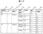
- FIG. 13 is a diagram illustrating a configuration example of the virtual logical volume management table 1300.
- the information collection program 0811 stores the information of the virtual logical volume 0205 collected from the controller storage device 0101 and the placement destination optimization program 0812 sets each logical as the data storage destination of the virtual logical volume 0205. An evaluation value obtained by evaluating the volume is stored.
- the virtual logical volume management table 1300 includes a virtual logical volume ID 1301, a pool ID 1302, a storage device ID 1303, a storage destination storage device ID 1304, an evaluation value 1305, a logical volume ID 1306, and a volume evaluation value 1307 as configuration items. Have.
- the virtual logical volume ID 1301 is information for uniquely identifying and identifying the virtual logical volume created in the computer system 0100.
- the pool ID 1302 is information for uniquely identifying and identifying the storage pool 0204 that holds the corresponding virtual logical volume.
- the storage device ID 1303 is information for uniquely identifying and identifying the storage device (controller storage device 0101) that stores the corresponding virtual logical volume.
- the storage destination storage apparatus ID 1304 is information for uniquely identifying and identifying a storage apparatus that holds a storage area for storing actual data provided to the corresponding virtual logical volume.
- the logical volume ID 1306 is information for uniquely identifying and identifying the logical volume that constitutes the virtual logical volume.
- the virtual logical volume ID 1301, pool ID 1302, storage device ID 1303, storage destination storage device ID 1304, and logical volume ID 1306 are acquired by the information collection program 0811 and stored in the virtual logical volume management table 1300.
- Evaluation value 1305 is information indicating how appropriate the storage device of the logical volume providing the storage area for storing the data of the virtual logical volume.
- the evaluation value 1305 for example, a value determined by I / O characteristics is input.
- the volume evaluation value 1307 is information indicating the evaluation of the logical volume.
- the I / O characteristic (access pattern) of the virtual logical volume V1 of the storage apparatus A is an access pattern in which random access is 80% and a load is applied to the disk apparatus side.
- the Busy Rate of the RAID group created from RG1 of the storage apparatus A is 80%. Therefore, the volume evaluation value 1307 is low because no more load can be applied to the disk device. Referring to FIG.
- the RG 3 that configures the logical volumes 4 and 5.
- the Busy Rate of RG is 0%, and there is a margin in the operating state of the disk device. Therefore, the volume evaluation value 1307 is relatively high. Information of the evaluation value 1305 and the volume evaluation value 1307 is obtained when the placement destination optimization program 0812 executes arithmetic processing described later.
- FIG. 14 is a diagram showing a configuration example of a port management table 1400 for managing the WWN of the SAN port of each device connected to the SAN 0145.
- the configuration information of the port management table 1400 is collected from the host 0107 via the LAN 0106 by the information collection program 0811.
- the port management table 1400 includes device ID 1091401 and WWN 1402 as configuration items.
- the device ID 1401 is information for uniquely identifying and identifying the device for which information is collected.
- the WWN 1402 is WWN information collected from the corresponding device.
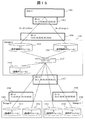
- FIG. 15 is a diagram showing the logical structure of each device, each logical volume, and each port reproduced from the tables 1000 to 1200 and 1400 (FIGS. 10 to 12 and FIG. 14).
- FIG. The management server 0103 can grasp the logical configuration in the computer system 0100 as follows, for example.
- the logical volumes 1510 to 1514 and the virtual logical volumes 1515 and 1516 included in the respective storage apparatuses 1502 to 1504 are arranged. Further, based on the information of the allocation source 1103, the allocation destination 1104, and the target ID 110 in the path management table 1100, the connection relationship between the logical volumes 1510 to 1516 and the ports 1505 to 1509 is clarified.
- pool management table 1200 it can be seen that a pool is set in the storage device A 1502, and therefore the logical volume 1_1510 and the external logical volumes 2 to 5_1511 to 1514 constituting the pool are associated with the pool 1_1517. .
- the management server 0103 can grasp the logical configuration in the computer system 0100 based on the collected information.
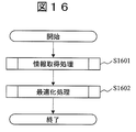
- FIG. 16 is a flowchart for explaining an outline of processing executed by the management server 0103.
- the processing executed by the management server 0103 includes information acquisition processing and optimization processing.
- the former is executed by the information collection program 0811, and the latter is executed by the placement destination optimization program 0812.
- step S1601 the information collection program 0811 collects predetermined information (information to be stored in each table in FIGS. 9 to 14) from the controller storage device 0101, the external connection storage device 0102, and the host 0107, and stores the corresponding table. Store in each column. Details of the processing in this step will be described with reference to FIG.
- step S1602 when the placement destination optimization program 0812 stores the page data of the virtual logical volume 0205 based on the information collected in step S1001, which logical volume in the logical volume constituting the storage pool 0204 is desirable. Are set in the controller storage device 0101. Details of the processing in this step will be described with reference to FIG.
- the main processing in the present embodiment is to collect necessary predetermined information from each device and determine the optimum storage destination of data to be stored in the virtual logical volume.
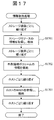
- FIG. 17 is a flowchart for explaining details of the information acquisition process (S1601).
- the information collection program 0811 collects information from each device and stores the data in the corresponding table.
- Step S1701 The information collection program 0811 acquires resource information from the storage apparatus and stores it in the resource performance table 0900. More specifically, the information collection program 0811 acquires the configuration information of each resource, the information on the type of each resource, and the information on the performance value of each resource from each device, and stores these information in the resource performance table 0900. Store. The following describes the types of resources to be acquired and how to store them.
- the information collection program 0811 stores the identification information of the storage device from which information is acquired in the storage device ID 1002 of the logical volume management table 1000. Further, the information collection program 0811 stores the identification information of the RAID group that provides the logical volume in the RAID group ID 1003. Further, the information collection program 0811 stores the identification information of the logical volume in the information acquisition target storage apparatus in the logical volume ID 1001.
- the information collection program 0811 collects the path information of the logical volume or virtual logical volume disclosed to the host or other storage apparatuses from the storage apparatus from which information is acquired, and stores it in the path management table 1100.
- the information collection program 0811 confirms whether the acquired route information is already stored in the allocation source 1103, the allocation destination 1104, and the target ID 1105.
- the information collection program 0811 stores the identification information of the storage apparatus from which the information is acquired and the identification information of the volume in the storage apparatus ID 1101 and the volume ID 1102. If the path is not stored in the above confirmation, the information collection program 0811 stores the path information in the allocation source 1103, the allocation destination 1104, and the target ID 1105 as new records.
- the information collection program 0811 stores the storage device ID and volume ID information in the added record.
- the information collection program 0811 stores information in the pool management table 1200 for each logical volume constituting the storage pool 0204. That is, the pool ID 1201 and the storage device ID 1202 store the storage pool identification information and the storage device identification information.
- the record ID 1206 stores information for uniquely identifying each entry in the pool management table 1200.
- the information collection program 0811 displays the identification information of the logical volume. Stored in the logical volume ID 1203.
- the logical volume constituting the storage pool 0204 is a logical volume that is disclosed (attached) from a storage device (externally connected storage device) other than the storage device in which the storage pool 0204 is located, the information collection program 0811 Then, the public path of the logical volume is searched from the path management table 1100.
- the information collection program 0811 stores the information stored in the record ID 1206 of the pool management table in the pool management table ID 1106. In addition, since the order of storing changes depending on the order of acquisition, information is stored in each column in the order in which the information is found.
- the information collection program 0811 adds the published logical volume route to the path management table 1100 as a new record. That is, the information collection program 0811 stores the allocation source 1103, the allocation destination 1104, and the target ID 1105 of the disclosed logical volume as path information. Then, the information collection program 0811 stores the information stored in the record ID 1206 column of the pool management table 1200 in the pool management table ID 1106.
- the information collection program 0811 For each virtual logical volume 0205, the information collection program 0811 stores the identification information of the storage pool 0204 in which the virtual logical volume 0205 is configured and the identification information of the storage device in the virtual logical volume management table 1300.
- Step S1702 is a process for storing the identification information of the externally connected storage device and the identification information of the external logical volume in the pool management table 1200 when the logical volume associated with the storage pool 0204 is in the externally connected storage device 0102. is there.
- the information collection program 0811 confirms the entry (record) of the pool management table 1200 from the top. If there is a record that does not contain a value in the logical volume ID 1203, the information collection program 0811 displays a record in which the same value as the record ID 1206 of the record is stored in the pool management table ID 1106 of the path management table 1100. Search from. Then, the information collection program 0811 stores the values of the storage device ID 1101 and the volume ID 1102 of the record found by the search in the external storage device ID 1204 and the external logical volume ID 1205 of the pool management table 1200.
- Step S1703 The information collection program 0811 acquires the WWN of the SAN port 0173 of the host 0107 and stores it in the port management table 1400.
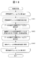
- FIG. 18 is a flowchart for explaining the details of the optimization process (S1602).
- the placement destination optimization program 0812 evaluates on which logical volume the data of the virtual logical volume 0205 is placed, and sets the storage location in the storage device.
- the evaluation outline and principle will be described first, and then each step showing a specific evaluation process will be described.
- the placement destination optimization program 0812 determines the I / O characteristics (random access and sequential access to the virtual logical volume 0205) based on the information acquired from each device in the computer system 0100 in step S1601. From the ratio and / or the ratio between the read request and the write request), it is determined which type of hardware is used to improve the response.
- the placement destination optimization program 0812 specifies a storage device that can use the hardware recognized by the above-described determination in the computer system environment or can use it a lot. Finally, the controller storage device 0101 is controlled so that data is stored in the storage device.
- the ratio of random access to sequential access is used as the I / O characteristic of the volume to the virtual logical volume 0205.
- the hardware evaluation method based on the I / O characteristics is that if the drive type is good in the case of random access, the response tends to improve.
- the cache capacity (remaining capacity) used is large, the response Is based on the recognition that is likely to improve.
- the random access ratio to the virtual logical volume 0205 is high, the evaluation of a logical volume with a good drive type (and a low Busy Rate of the drive) is made high.
- the sequential access ratio is high, the evaluation of a logical volume having a large cache capacity that is not used is made high.
- the storage device evaluation value and the logical volume I / O property are set. Evaluate in combination. More specific evaluation combination methods include evaluation of hardware (CPU, cache) information that affects the entire storage device, and information of hardware (RAID group, Drive) that affects only the logical volume. The storage evaluation value and the logical volume evaluation value are used.
- the logical volume as the optimum placement destination is determined by selecting the logical volume with the high evaluation value from the logical volumes with the high evaluation value of the storage device.
- a method other than the above-described method of combining the two evaluation values there are a method of weighting the sum of the evaluation value of the storage device and the evaluation value of the logical volume, and a method of taking the product of them. That is, for example, when data is distributed to a plurality of storage devices, the possibility of being affected by a failure of the storage device increases. For this reason, data of the same host may be stored in a single storage device as much as possible. In this case, an evaluation method of selecting a storage device with a high evaluation value and selecting a logical volume among them is taken.
- the sum is calculated by weighting the evaluation value of the storage device and the evaluation value of the logical volume.
- the method to take and the method to take each product are selected. Even in this case, based on the information on how much storage device data of the same host can be distributed, the weighting is applied to the evaluation values of the storage device and the logical volume.
- step S1801 the placement destination optimization program 0812 determines how to evaluate the logical volume as the data storage destination of the virtual logical volume 0205, parameters a and b in the following (formula 1) and (formula 2). To decide. In other words, a virtual logical volume to be evaluated is specified, information on what access pattern is accessed, information such as CPU specifications, and the like are acquired, and parameters are determined.
- the storage device and volume evaluation values are determined as follows.
- Storage evaluation value a * (CPU spec) * (100- (CPU Busy Rate)) + b * (Cache size) * (100- (Cache Hit Rate)) (Formula 1)
- Logical volume evaluation value (RAID group drive type) * (100- (Drive Busy Rate)) (Equation 2)
- “a” and “b” represent the importance ratio of the CPU and the cache, respectively, and are the same ratio as the ratio of random access and sequential access of I / O to the virtual volume.
- the CPU specification is a value obtained by re-scaling the computer specification with the highest CPU specification to 1 and the lowest with 0 in the computer system 0100.
- the cache size is a value obtained by re-scaling the largest cache size to 1 and the lowest one to 0 in the computer system 0100.
- the drive type of the RAID group is calculated by subtracting the value obtained by dividing 1 by the number of drive types in the computer system every time the specification of the drive type is lowered by 1 when the specification of the drive type is high. It is.
- an evaluation value is calculated by a read / write ratio (Read / write characteristic), or an evaluation value is added to a ratio of random access and sequential access and a read / write ratio is added. You may make it calculate. For example, in the case of random access, the remaining capacity of the cache is hardly considered at the time of reading (Case 1). In the case of sequential access, the remaining capacity of the cache tends to be emphasized at the time of reading (Case 2). In general, when there are many write requests, even if the remaining cache capacity is large, the response will not be affected. May affect the response to I / O requests (Case 3).
- the remaining capacity of the cache may be affected, but as a general rule, it is difficult to determine the rules for determining the parameters a and b, and whether or not to place importance on each event differs.
- a logical volume with a high evaluation of the logical volume is selected among the above-mentioned storage device having a high evaluation value.
- Other methods of comprehensive evaluation of logical volumes include a method of taking the sum or product of storage device evaluation and logical volume evaluation and selecting from the computer system regardless of the storage device. Further, when the table is configured so that the resource performance table 0900 includes information on past performance values, the storage device evaluation and the logical volume evaluation calculation are performed by weighting the past performance value information. There is also a way to reflect it.
- step S1802 the placement destination optimization program 0812 evaluates each logical volume according to the evaluation method determined in step S1801 (using the determined parameter), and stores the evaluation value in the virtual logical volume management table 1300. Then, the placement destination optimization program 0812 stores information for identifying the evaluated logical volume and the storage device (storage destination storage device) in which the logical volume is stored in the logical volume ID 1306 and the storage destination storage device ID 1304. . The placement destination optimization program 0812 stores the evaluation value of the storage device and the evaluation value of the logical volume in the evaluation value 1305 and the volume evaluation value 1307, respectively.
- the processing in step S1802 is repeatedly executed for each logical volume that configures the storage pool 0204 that provides the virtual logical volume.
- the logical volume constituting the storage pool 0204 to be processed is the storage device ID 1202 and logical volume ID 1403 in which the identification information of the storage pool 0204 is stored in the pool ID 1201 of the pool management table 1200, or the external storage device ID 1204 and The external logical volume ID 1205 can be specified.
- step S1803 the allocation destination optimization program 0812 determines the priority of the logical group used as the page allocation destination of the virtual logical volume 0205, and sets it in the controller storage device 0101. In this embodiment, settings are made so that logical volumes included in a storage device with a high evaluation value are used in descending order of the evaluation value of the logical volume.
- the placement destination optimization program 0812 repeatedly executes the processing from steps S1801 to S18203 for the virtual logical volumes managed by the virtual logical volume management table 1300.
- the controller storage device 0101 allocates a page of the virtual logical volume 0205 to the logical volume with a high evaluation value determined according to step S1803, using the virtual logical volume expansion policy designation function.
- the virtual logical volume 0205 is used by using the migration function. It is also possible to move from the logical volume storing the page 0206 to the storage area of the logical volume specified in step S1203. Further, the data of the virtual logical volume 0205 can be moved to the logical volume of the controller storage device 0101 or the logical volume assigned to the controller storage device 0101 by the external connection storage device 0102 using the migration function.
- migration function migration function
- FIG. 19 is a diagram illustrating a configuration example of an arrangement destination display GUI screen after the optimization process generated by the arrangement destination information input / output program 0813.
- the GUI screen 1900 displays the status of the virtual logical volume, whereby the administrator (user) can instruct setting change.
- the placement destination information input / output program 0813 first includes information on the host 0107 that is using the virtual logical volume, I / O characteristics (also referred to as access characteristics: ratio of random access to sequential access, Read / Write). (Ratio) information is displayed on the screen. At this time, the administrator can change the access characteristics held by the placement destination information input / output program 0813 by pressing the Edit button.
- I / O characteristics also referred to as access characteristics: ratio of random access to sequential access, Read / Write.
- (Ratio) information is displayed on the screen.
- the administrator can change the access characteristics held by the placement destination information input / output program 0813 by pressing the Edit button.
- the storage destination definition (storage device, volume) of each virtual logical volume set in step S1803 is displayed.
- This storage destination definition information can also be edited when the administrator presses the Edit button, and the setting can be changed as appropriate.
- the current storage destination volume indicates the volume in which the virtual logical volume is currently stored.
- the priority assignment destination volume indicates a volume to which the corresponding virtual logical volume is to be preferentially assigned as a result of the evaluation.
- the volume to be stored matches the volume currently stored.
- all data should be stored in the priority allocation destination volume, but is currently stored in another volume.
- the data may be automatically migrated, or the administrator (user) may be instructed to migrate. . This is because it takes a load to execute the migration process, so it is not preferable to execute it frequently, and it may be more efficient to execute it only when there is an instruction from the administrator.
- the GUI screen 1900 displays the performance information of the logical volume constituting the pool or the storage device to which the logical volume belongs as the detailed information of the pool selected from the drop-down menu.
- the administrator can use the GUI screen 1900 to do at least the following three.
- the administrator can confirm the performance information and configuration information of the virtual logical volume. Thereby, the administrator (user) can grasp at a time the information on the access characteristics of the virtual logical volume, the storage destination definition of the data of the virtual logical volume, and the performance information of the pool to which the virtual logical volume belongs.
- (Iii) Storage Location Setting The administrator can set storage location definition information using this GUI screen 1900. As a result, the administrator can designate the storage location of the data of the virtual logical volume as a specific storage, or can partially change the result of step S1602.
- Second Embodiment instead of the controller storage device 0101 in the first embodiment, a switch or application server that provides a virtual technology for managing a storage area across a plurality of externally connected storage devices is used. You can also.
- a switch or application server that provides virtualization technology is connected to the SAN 0145 and the LAN 0106 in the same manner as the controller storage device 0101.
- the switch and application server that provide the virtualization technology it is necessary for the switch and application server that provide the virtualization technology to have the same function as the storage control program 0114.
- the logical storage area configuration function possessed by the storage control program 0114 does not hold the function of constructing the RAID group 0201 and the logical volume 0202.
- the storage control program is a virtual machine control program.
- virtual machine software (hypervisor) on a server is used as a virtual technique for centrally managing storage areas spanning a plurality of externally connected storage apparatuses 0102.
- the virtual machine software has a function of constructing a virtual machine on a volume allocated from a plurality of storage devices.
- 2nd Embodiment is a modification of 1st Embodiment, it replaces with description about all the structure and operation
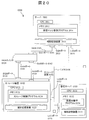
- FIG. 20 is a diagram showing a schematic configuration of a computer system 0200 according to the second embodiment.
- the computer system 0200 includes a server 2001, at least one externally connected storage device 0102, a management server 0103, and a SAN (Storage Area Network) switch 0104.
- the server 2001 and the externally connected storage device 0102 are connected by SAN0145.
- the server 2001, the storage device 0102, and the management server are connected by a LAN (Local Area Network) 0106.
- LAN Local Area Network
- the server 2001 has a SAN port 2015 and is connected to the SAN 0105 via the SAN port 2015.
- the server 2001 has a LAN port 2016 and is connected to the LAN 0106 through the LAN port 2016.
- the server 2001 includes a CPU 2011, a memory 2012, and an auxiliary storage device 2013.
- the CPU 2011 performs various processes by executing the virtual machine control program 2014 stored in the memory 2012.
- the memory 2012 stores information necessary for the CPU 2011 to execute the virtual machine control program 2014.
- the auxiliary storage device 2013 is handled as a storage area by the virtual machine control program 2014 as described later.
- the auxiliary storage device 2013 is composed of one in the drawing, but is not limited to one and may be composed of a plurality of auxiliary storage devices. Examples of the auxiliary storage device 2013 include an FC (Fibre Channel) disk and an SSD (Solid State Drive).
- the controller storage device 0101 is read as the server 2001 in FIG.
- the memory 0112 is read as the memory 2012.
- the auxiliary storage device 0113 is read as the auxiliary storage device 2013.
- the storage control program 0114 is read as the virtual machine control program 2014.
- the virtual logical volume 0205 is read as a virtual machine storage area.
- the storage pool 0204 is read as virtual machine software.
- the virtual logical volume 0205 is read as a virtual machine (VM).
- the virtual machine control program 2014 has substantially the same function as the storage control program 0114 in the first embodiment. More specifically, the virtual machine control program 2014 has a logical storage area configuration function, a virtual logical volume expansion function (a function that allocates page 0206 to a virtual machine in accordance with an I / O command from a device to which a volume is allocated). And a virtual logical volume expansion policy designation function (a function for designating page candidates to be allocated in advance when a virtual machine storage area is expanded), and a performance information collection function. However, the virtual machine control program 2014 does not have a logical volume assignment function.
- the logical configuration of the management server 0103 is shown in FIG. 8 as in the first embodiment. Therefore, the description is omitted.
- the virtual machine storage area management table stores information for managing an area for storing each virtual machine, and a configuration example thereof can be represented by a virtual logical volume management table 1300.
- storage A controller storage device 0101
- the virtual logical volume is replaced with a virtual machine storage area.
- the storage destination storage apparatus ID 1304 stores identification information of the externally connected storage apparatus 0102 that provides the logical volume or identification information of the server 2001.
- the virtual logical volume is read as a virtual machine storage area. Further, the controller storage device 0101 is read as the server 2001.
- step S1701 is repeatedly executed for each externally connected storage device 0102 and server 2001.
- the virtual logical volume is read as a virtual machine storage area.
- the controller storage device 0101 is read as the server 2001.
- the storage control program 0114 is read as the virtual machine control program 2014.
- the virtual logical volume is replaced with a virtual machine storage area.
- Information identifying the server 2001 is stored in the storage device ID 1303 of the virtual machine memory management table.
- the virtual logical volume may be read as a virtual machine storage area.
- a logical volume management program that can virtually configure a logical volume across volumes allocated from a plurality of externally connected storage apparatuses can be used.
- a file system that can configure a file system across multiple volumes can be used.
- the virtual machine of the server 2001 can be provided as a file system.
- the management system is a virtual layer (when the information processing is a controller storage device, for example, a controller storage device or a server device that provides a virtual server) of the information processing device. If the storage pool or information processing device is a server device, it is managed on a virtual instance (equivalent to virtual machine software (hypervisor)) (if the information processing device is a controller storage device, a virtual logical volume, and the information processing device is In this case, logical volume configuration information assigned to a virtual server) and hardware resource operation information included in an externally connected storage device are managed.
- a virtual instance equivalent to virtual machine software (hypervisor)
- the information processing device is a controller storage device, a virtual logical volume, and the information processing device is In this case, logical volume configuration information assigned to a virtual server
- hardware resource operation information included in an externally connected storage device are managed.
- the management system performs evaluation (calculation) on the utilization efficiency of the virtual instance based on the logical volume configuration information and hardware resource operation information, and outputs the evaluation result.
- evaluation calculation
- the administrator can determine whether the usage efficiency of the currently operating virtual instance is good, and can take measures if the efficiency is low.
- the management system evaluates the usage efficiency of the virtual instance in consideration of access characteristic information (I / O characteristic) indicating the access characteristic for the virtual instance.
- access characteristic information I / O characteristic
- the utilization efficiency of the virtual instance is evaluated in consideration of the access pattern indicated by the I / O characteristic. Therefore, rather than just considering the load on the RAID group of the externally connected storage device, the use efficiency is improved according to the load (cache remaining capacity or processor load) in the externally connected storage device when accessed by a specific access method. evaluate. By doing so, the utilization efficiency can be accurately evaluated.
- the utilization efficiency of the virtual instance is evaluated by evaluating the response to the I / O request of the storage subsystem and the load on the logical volume with which the virtual instance is associated. Further, the importance (weighting coefficient) of the hardware resource of the storage subsystem in the evaluation calculation is determined according to the access characteristic information (access tendency), and the responsiveness of the storage subsystem in the access characteristic is evaluated. Further, the disk drive load of the storage subsystem that provides the logical volume is evaluated.
- the management system outputs (for example, GUI) an optimal logical volume to be associated with the virtual instance as an evaluation result. By doing so, it is possible to confirm whether the logical volume with which the virtual instance is associated is optimal.
- the management system automatically or in response to the input instruction May be executed to change the logical volume of the allocation destination. By doing so, the virtual instance can use the optimum logical volume.
- a controller storage device can be used as the information processing device.
- the upper limit value and current value of the performance of various hardware in the computer system are collected.
- the optimal location is determined as the data storage destination (logical volume of the externally connected storage device) from the computer system,
- the optimal storage location is output as the evaluation result.
- an optimal location is set in the controller storage device to control the data storage location.
- the data storage location is determined based on past I / O characteristics and user-defined characteristics (setting of access characteristics by the user).
- the present invention can also be realized by a program code of software that realizes the functions of the embodiment.
- a storage medium in which the program code is recorded is provided to the system or apparatus, and the computer (or CPU or MPU) of the system or apparatus reads the program code stored in the storage medium.
- the program code itself read from the storage medium realizes the functions of the above-described embodiments, and the program code itself and the storage medium storing the program code constitute the present invention.
- a storage medium for supplying such program code for example, a flexible disk, CD-ROM, DVD-ROM, hard disk, optical disk, magneto-optical disk, CD-R, magnetic tape, nonvolatile memory card, ROM Etc. are used.
- an OS operating system
- the computer CPU or the like performs part or all of the actual processing based on the instruction of the program code.
- the program code is stored in a storage means such as a hard disk or memory of a system or apparatus or a storage medium such as a CD-RW or CD-R
- the computer (or CPU or MPU) of the system or apparatus may read and execute the program code stored in the storage means or the storage medium when used.
- control lines and information lines indicate what is considered necessary for the explanation, and not all control lines and information lines on the product are necessarily shown. All the components may be connected to each other.
- 0100 Computer system 0101 ... Controller storage device 0102 ... Externally connected storage device 0103 ... Management server 0104 ... SAN switch 0106 ... LAN 0107: Host 0111, 0121, 0131, 0171, 2011 ... CPU 0112, 0122, 0172, 0132, 2012 ... Memory 0113, 0123, 0133, 0175, 2013 ... Auxiliary storage devices 0114, 0124 ... Storage control programs 0134, 0801 ... Placement management program 0201 ... RAID group 0202, 0203 ... logical volume 0204 ... storage pool 0205 ... virtual logical volume 0206 ... page 0300 ... RAID group management table 0400 ... volume management table 0500 ... storage pool Configuration table 0600 ...
- Page configuration table 0700 ... Performance information table 0811 ... Information collection program 0812 ... Placement destination optimization program 0813 ... Placement destination information input / output program 0900 Resource performance table 1000 ... Logical volume management table 1100 ... Path management table 1200 ... Pool management table 1300 ... Virtual logical volume management table 1400 ... Port management table 1900 ... GUI screen 2001 ... Server 2014 ... Virtual machine control program
Landscapes
- Engineering & Computer Science (AREA)
- Theoretical Computer Science (AREA)
- Human Computer Interaction (AREA)
- Physics & Mathematics (AREA)
- General Engineering & Computer Science (AREA)
- General Physics & Mathematics (AREA)
- Information Retrieval, Db Structures And Fs Structures Therefor (AREA)
Abstract
Priority Applications (3)
| Application Number | Priority Date | Filing Date | Title |
|---|---|---|---|
| US13/139,872 US8863139B2 (en) | 2011-04-12 | 2011-04-12 | Management system and management method for managing a plurality of storage subsystems |
| PCT/JP2011/059064 WO2012140730A1 (fr) | 2011-04-12 | 2011-04-12 | Système de gestion, système informatique doté de celui-ci et procédé de gestion |
| JP2013509688A JP5661921B2 (ja) | 2011-04-12 | 2011-04-12 | 計算機システム及び管理システム |
Applications Claiming Priority (1)
| Application Number | Priority Date | Filing Date | Title |
|---|---|---|---|
| PCT/JP2011/059064 WO2012140730A1 (fr) | 2011-04-12 | 2011-04-12 | Système de gestion, système informatique doté de celui-ci et procédé de gestion |
Publications (1)
| Publication Number | Publication Date |
|---|---|
| WO2012140730A1 true WO2012140730A1 (fr) | 2012-10-18 |
Family
ID=47007383
Family Applications (1)
| Application Number | Title | Priority Date | Filing Date |
|---|---|---|---|
| PCT/JP2011/059064 Ceased WO2012140730A1 (fr) | 2011-04-12 | 2011-04-12 | Système de gestion, système informatique doté de celui-ci et procédé de gestion |
Country Status (3)
| Country | Link |
|---|---|
| US (1) | US8863139B2 (fr) |
| JP (1) | JP5661921B2 (fr) |
| WO (1) | WO2012140730A1 (fr) |
Cited By (6)
| Publication number | Priority date | Publication date | Assignee | Title |
|---|---|---|---|---|
| WO2014064756A1 (fr) * | 2012-10-22 | 2014-05-01 | 株式会社日立製作所 | Procédé permettant d'attribuer des zones de stockage réelles d'un pool de stockage à un volume virtuel, et système informatique |
| WO2015022908A1 (fr) * | 2013-08-12 | 2015-02-19 | 日本電気株式会社 | Système de fourniture de mémoire, dispositif de sélection de mémoire, procédé de fourniture de mémoire et programme |
| JP2015158725A (ja) * | 2014-02-21 | 2015-09-03 | 富士通株式会社 | ストレージ制御装置、ストレージ装置及びストレージ制御プログラム |
| JP2015191534A (ja) * | 2014-03-28 | 2015-11-02 | 富士通株式会社 | サーバ装置、情報格納プログラム、及び情報格納方法 |
| WO2016117019A1 (fr) * | 2015-01-20 | 2016-07-28 | 株式会社日立製作所 | Système de mémorisation et procédé de commande d'un dispositif de mémorisation |
| JP2018128751A (ja) * | 2017-02-07 | 2018-08-16 | 日本電気株式会社 | ディスク制御装置、ディスク制御方法、および、ディスク制御プログラム |
Families Citing this family (26)
| Publication number | Priority date | Publication date | Assignee | Title |
|---|---|---|---|---|
| JP5821392B2 (ja) * | 2011-08-12 | 2015-11-24 | 富士通株式会社 | ストレージ装置、およびストレージ管理方法 |
| US9274817B1 (en) * | 2012-12-31 | 2016-03-01 | Emc Corporation | Storage quality-of-service control in distributed virtual infrastructure |
| US9960979B1 (en) * | 2013-03-12 | 2018-05-01 | Western Digital Technologies, Inc. | Data migration service |
| US9195401B2 (en) | 2014-02-18 | 2015-11-24 | University Of Florida Research Foundation, Inc. | Method and apparatus for virtual machine live storage migration in heterogeneous storage environment |
| US9052938B1 (en) * | 2014-04-15 | 2015-06-09 | Splunk Inc. | Correlation and associated display of virtual machine data and storage performance data |
| JP6428231B2 (ja) * | 2014-12-15 | 2018-11-28 | 富士通株式会社 | ストレージ管理装置、性能調整方法及び性能調整プログラム |
| CN104598318B (zh) * | 2014-12-30 | 2018-12-04 | 北京奇艺世纪科技有限公司 | 节点计算能力的汇报方法和计算节点 |
| US10778664B1 (en) * | 2015-05-14 | 2020-09-15 | Amazon Technologies, Inc. | Software asset management of computer systems and virtual instances for reporting and optimization |
| US10599352B2 (en) * | 2015-08-14 | 2020-03-24 | Samsung Electronics Co., Ltd. | Online flash resource allocation manager based on a TCO model |
| US9706391B2 (en) * | 2015-10-08 | 2017-07-11 | At&T Intellectual Property I, L.P. | Initiating signaling in mobile management entity pools using workflows |
| CN105354090B (zh) * | 2015-10-16 | 2019-04-16 | 安一恒通(北京)科技有限公司 | 虚拟设备的管理方法和装置 |
| JP6877381B2 (ja) * | 2018-03-20 | 2021-05-26 | 株式会社東芝 | 情報処理装置、情報処理方法およびプログラム |
| JP6800904B2 (ja) | 2018-03-20 | 2020-12-16 | 株式会社東芝 | モデル生成装置、情報処理装置、モデル生成方法およびプログラム |
| US10719247B2 (en) * | 2018-03-20 | 2020-07-21 | Kabushiki Kaisha Toshiba | Information processing device, information processing method, estimation device, estimation method, and computer program product |
| US11249852B2 (en) | 2018-07-31 | 2022-02-15 | Portwonx, Inc. | Efficient transfer of copy-on-write snapshots |
| US11354060B2 (en) | 2018-09-11 | 2022-06-07 | Portworx, Inc. | Application snapshot for highly available and distributed volumes |
| US11169726B2 (en) * | 2018-09-13 | 2021-11-09 | Toshiba Memory Corporation | Pool-level storage management |
| US11500874B2 (en) * | 2019-01-23 | 2022-11-15 | Servicenow, Inc. | Systems and methods for linking metric data to resources |
| WO2021126216A1 (fr) | 2019-12-19 | 2021-06-24 | Google Llc | Unité de gestion de ressources pour capturer des états de configuration de système d'exploitation et des tâches de délestage |
| WO2021126217A1 (fr) | 2019-12-19 | 2021-06-24 | Google Llc | Unité de gestion de ressources pour capturer des états de configuration de système d'exploitation et gestion de mémoire |
| US11494128B1 (en) | 2020-01-28 | 2022-11-08 | Pure Storage, Inc. | Access control of resources in a cloud-native storage system |
| US11531467B1 (en) | 2021-01-29 | 2022-12-20 | Pure Storage, Inc. | Controlling public access of resources in a secure distributed storage system |
| US11520516B1 (en) | 2021-02-25 | 2022-12-06 | Pure Storage, Inc. | Optimizing performance for synchronous workloads |
| US11733897B1 (en) | 2021-02-25 | 2023-08-22 | Pure Storage, Inc. | Dynamic volume storage adjustment |
| US11726684B1 (en) | 2021-02-26 | 2023-08-15 | Pure Storage, Inc. | Cluster rebalance using user defined rules |
| US12235807B2 (en) | 2023-02-15 | 2025-02-25 | Pure Storage, Inc. | Backend storage system implementing multiple data management models |
Citations (4)
| Publication number | Priority date | Publication date | Assignee | Title |
|---|---|---|---|---|
| JP2004206623A (ja) * | 2002-12-26 | 2004-07-22 | Fujitsu Ltd | ストレージシステム及びその動的負荷管理方法 |
| JP2007299256A (ja) * | 2006-05-01 | 2007-11-15 | Hitachi Ltd | ストレージ資源管理システム、ストレージ資源管理方法および管理計算機 |
| JP2009238114A (ja) * | 2008-03-28 | 2009-10-15 | Hitachi Ltd | ストレージ管理方法、ストレージ管理プログラム、ストレージ管理装置およびストレージ管理システム |
| JP2010026919A (ja) * | 2008-07-23 | 2010-02-04 | Hitachi Ltd | ストレージシステム内の論理ユニットを論理ボリュームに割り当てる方法及び記憶制御装置 |
Family Cites Families (12)
| Publication number | Priority date | Publication date | Assignee | Title |
|---|---|---|---|---|
| US5581724A (en) * | 1992-10-19 | 1996-12-03 | Storage Technology Corporation | Dynamically mapped data storage subsystem having multiple open destage cylinders and method of managing that subsystem |
| US6529995B1 (en) * | 1999-06-18 | 2003-03-04 | Storage Technology Corporation | Method and apparatus for maintaining and restoring mapping table entries and data in a raid system |
| US20030061362A1 (en) * | 2000-03-03 | 2003-03-27 | Qiu Chaoxin C. | Systems and methods for resource management in information storage environments |
| US20020194251A1 (en) * | 2000-03-03 | 2002-12-19 | Richter Roger K. | Systems and methods for resource usage accounting in information management environments |
| JP4516306B2 (ja) * | 2003-11-28 | 2010-08-04 | 株式会社日立製作所 | ストレージネットワークの性能情報を収集する方法 |
| JP4806556B2 (ja) * | 2005-10-04 | 2011-11-02 | 株式会社日立製作所 | ストレージシステム及び構成変更方法 |
| JP2008234059A (ja) * | 2007-03-16 | 2008-10-02 | Fujitsu Ltd | データ転送装置および情報処理システム |
| JP5134915B2 (ja) * | 2007-11-02 | 2013-01-30 | 株式会社日立製作所 | 記憶領域の構成最適化方法、計算機システム及び管理計算機 |
| JP2009223442A (ja) * | 2008-03-13 | 2009-10-01 | Hitachi Ltd | ストレージシステム |
| JP4920658B2 (ja) * | 2008-10-20 | 2012-04-18 | 株式会社日立製作所 | 電力推定方法及び計算機システム |
| JP2010170411A (ja) * | 2009-01-23 | 2010-08-05 | Hitachi Ltd | 計算機システム、ストレージプール管理方法 |
| GB2496556B (en) * | 2011-02-24 | 2013-11-13 | Hitachi Ltd | Computer system and management method for the computer system and program |
-
2011
- 2011-04-12 JP JP2013509688A patent/JP5661921B2/ja not_active Expired - Fee Related
- 2011-04-12 US US13/139,872 patent/US8863139B2/en not_active Expired - Fee Related
- 2011-04-12 WO PCT/JP2011/059064 patent/WO2012140730A1/fr not_active Ceased
Patent Citations (4)
| Publication number | Priority date | Publication date | Assignee | Title |
|---|---|---|---|---|
| JP2004206623A (ja) * | 2002-12-26 | 2004-07-22 | Fujitsu Ltd | ストレージシステム及びその動的負荷管理方法 |
| JP2007299256A (ja) * | 2006-05-01 | 2007-11-15 | Hitachi Ltd | ストレージ資源管理システム、ストレージ資源管理方法および管理計算機 |
| JP2009238114A (ja) * | 2008-03-28 | 2009-10-15 | Hitachi Ltd | ストレージ管理方法、ストレージ管理プログラム、ストレージ管理装置およびストレージ管理システム |
| JP2010026919A (ja) * | 2008-07-23 | 2010-02-04 | Hitachi Ltd | ストレージシステム内の論理ユニットを論理ボリュームに割り当てる方法及び記憶制御装置 |
Cited By (6)
| Publication number | Priority date | Publication date | Assignee | Title |
|---|---|---|---|---|
| WO2014064756A1 (fr) * | 2012-10-22 | 2014-05-01 | 株式会社日立製作所 | Procédé permettant d'attribuer des zones de stockage réelles d'un pool de stockage à un volume virtuel, et système informatique |
| WO2015022908A1 (fr) * | 2013-08-12 | 2015-02-19 | 日本電気株式会社 | Système de fourniture de mémoire, dispositif de sélection de mémoire, procédé de fourniture de mémoire et programme |
| JP2015158725A (ja) * | 2014-02-21 | 2015-09-03 | 富士通株式会社 | ストレージ制御装置、ストレージ装置及びストレージ制御プログラム |
| JP2015191534A (ja) * | 2014-03-28 | 2015-11-02 | 富士通株式会社 | サーバ装置、情報格納プログラム、及び情報格納方法 |
| WO2016117019A1 (fr) * | 2015-01-20 | 2016-07-28 | 株式会社日立製作所 | Système de mémorisation et procédé de commande d'un dispositif de mémorisation |
| JP2018128751A (ja) * | 2017-02-07 | 2018-08-16 | 日本電気株式会社 | ディスク制御装置、ディスク制御方法、および、ディスク制御プログラム |
Also Published As
| Publication number | Publication date |
|---|---|
| JP5661921B2 (ja) | 2015-01-28 |
| US20120266177A1 (en) | 2012-10-18 |
| JPWO2012140730A1 (ja) | 2014-07-28 |
| US8863139B2 (en) | 2014-10-14 |
Similar Documents
| Publication | Publication Date | Title |
|---|---|---|
| JP5661921B2 (ja) | 計算機システム及び管理システム | |
| JP4235220B2 (ja) | 計算機システムおよびデータ移行方法 | |
| US9052823B2 (en) | Storage system and data management method with application specific storage tiers | |
| US8639899B2 (en) | Storage apparatus and control method for redundant data management within tiers | |
| US8918613B2 (en) | Storage apparatus and data management method for storage area allocation based on access frequency | |
| US8850152B2 (en) | Method of data migration and information storage system | |
| US9274723B2 (en) | Storage apparatus and its control method | |
| US7395396B2 (en) | Storage system and data relocation control device | |
| JP4814119B2 (ja) | 計算機システム、ストレージ管理サーバ、及びデータ移行方法 | |
| US8549247B2 (en) | Storage system, management method of the storage system, and program | |
| JP5363595B2 (ja) | 仮想ボリューム内のデータの再配置を行うストレージシステム及び方法 | |
| US8694727B2 (en) | First storage control apparatus and storage system management method | |
| JP5830599B2 (ja) | 計算機システム及びその管理システム | |
| JP4690765B2 (ja) | ストレージ管理システム、ストレージ管理サーバ、データ再配置制御方法およびデータ再配置制御プログラム | |
| US20150081964A1 (en) | Management apparatus and management method of computing system | |
| WO2014167716A1 (fr) | Système de gestion et procédé de gestion de système informatique | |
| US20150378848A1 (en) | Management computer and managment method of computer system | |
| JP2013045444A (ja) | データセンタ内のリソースの使用効率を改善するための方法及び装置 | |
| JP2011070345A (ja) | 計算機システム、計算機システムの管理装置、計算機システムの管理方法 | |
| WO2013046331A1 (fr) | Système informatique et procédé de gestion d'informations | |
| US20130080727A1 (en) | Computer system and storage management method | |
| WO2014155555A1 (fr) | Système de gestion et programme de gestion | |
| JP2016118821A (ja) | ストレージ管理装置、ストレージ管理方法およびストレージ管理プログラム | |
| JPWO2015198441A1 (ja) | 計算機システム、管理計算機、および管理方法 | |
| WO2013111331A1 (fr) | Système informatique |
Legal Events
| Date | Code | Title | Description |
|---|---|---|---|
| WWE | Wipo information: entry into national phase |
Ref document number: 13139872 Country of ref document: US |
|
| 121 | Ep: the epo has been informed by wipo that ep was designated in this application |
Ref document number: 11863419 Country of ref document: EP Kind code of ref document: A1 |
|
| ENP | Entry into the national phase |
Ref document number: 2013509688 Country of ref document: JP Kind code of ref document: A |
|
| NENP | Non-entry into the national phase |
Ref country code: DE |
|
| 122 | Ep: pct application non-entry in european phase |
Ref document number: 11863419 Country of ref document: EP Kind code of ref document: A1 |