WO2012140845A1 - インコヒーレント化デバイス、およびこれを用いた光学装置 - Google Patents
インコヒーレント化デバイス、およびこれを用いた光学装置 Download PDFInfo
- Publication number
- WO2012140845A1 WO2012140845A1 PCT/JP2012/002293 JP2012002293W WO2012140845A1 WO 2012140845 A1 WO2012140845 A1 WO 2012140845A1 JP 2012002293 W JP2012002293 W JP 2012002293W WO 2012140845 A1 WO2012140845 A1 WO 2012140845A1
- Authority
- WO
- WIPO (PCT)
- Prior art keywords
- laser beam
- diffraction grating
- incident
- diffraction
- optical member
- Prior art date
- Legal status (The legal status is an assumption and is not a legal conclusion. Google has not performed a legal analysis and makes no representation as to the accuracy of the status listed.)
- Ceased
Links
Images



Classifications
-
- G—PHYSICS
- G02—OPTICS
- G02B—OPTICAL ELEMENTS, SYSTEMS OR APPARATUS
- G02B27/00—Optical systems or apparatus not provided for by any of the groups G02B1/00 - G02B26/00, G02B30/00
- G02B27/48—Laser speckle optics
-
- G—PHYSICS
- G02—OPTICS
- G02B—OPTICAL ELEMENTS, SYSTEMS OR APPARATUS
- G02B17/00—Systems with reflecting surfaces, with or without refracting elements
- G02B17/004—Systems comprising a plurality of reflections between two or more surfaces, e.g. cells, resonators
-
- G—PHYSICS
- G02—OPTICS
- G02B—OPTICAL ELEMENTS, SYSTEMS OR APPARATUS
- G02B17/00—Systems with reflecting surfaces, with or without refracting elements
- G02B17/02—Catoptric systems, e.g. image erecting and reversing system
- G02B17/023—Catoptric systems, e.g. image erecting and reversing system for extending or folding an optical path, e.g. delay lines
-
- G—PHYSICS
- G03—PHOTOGRAPHY; CINEMATOGRAPHY; ANALOGOUS TECHNIQUES USING WAVES OTHER THAN OPTICAL WAVES; ELECTROGRAPHY; HOLOGRAPHY
- G03B—APPARATUS OR ARRANGEMENTS FOR TAKING PHOTOGRAPHS OR FOR PROJECTING OR VIEWING THEM; APPARATUS OR ARRANGEMENTS EMPLOYING ANALOGOUS TECHNIQUES USING WAVES OTHER THAN OPTICAL WAVES; ACCESSORIES THEREFOR
- G03B21/00—Projectors or projection-type viewers; Accessories therefor
- G03B21/14—Details
- G03B21/20—Lamp housings
- G03B21/2006—Lamp housings characterised by the light source
- G03B21/2033—LED or laser light sources
-
- G—PHYSICS
- G03—PHOTOGRAPHY; CINEMATOGRAPHY; ANALOGOUS TECHNIQUES USING WAVES OTHER THAN OPTICAL WAVES; ELECTROGRAPHY; HOLOGRAPHY
- G03B—APPARATUS OR ARRANGEMENTS FOR TAKING PHOTOGRAPHS OR FOR PROJECTING OR VIEWING THEM; APPARATUS OR ARRANGEMENTS EMPLOYING ANALOGOUS TECHNIQUES USING WAVES OTHER THAN OPTICAL WAVES; ACCESSORIES THEREFOR
- G03B21/00—Projectors or projection-type viewers; Accessories therefor
- G03B21/14—Details
- G03B21/20—Lamp housings
- G03B21/208—Homogenising, shaping of the illumination light
Definitions
- the present invention relates to an optical member (incoherent device) and an optical apparatus using the same.
- LEDs light-emitting diodes
- LDs lasers
- Lasers are characterized by high light intensity, narrow wavelength width, and high coherence compared to LEDs. Therefore, while a bright image can be obtained, for example, when used as a light source for a projector, noise called speckle appears in the projected image due to interference of scattered light due to minute irregularities on the screen or the like, which deteriorates the image quality. There is a problem that it is easy.
- One is based on the principle that the speckle is not perceived by the human eye by fluctuating the laser beam over time.
- Patent Document 1 discloses a method of reducing speckles by using a diffractive lens element in which a large number of concave portions having different depths are formed in a transparent substrate in an illumination device, and rotating the diffractive lens element.
- Patent Document 2 discloses a speckle removing device that uses a method of mechanically rotating and vibrating an optical retarder that provides a retardation that is an odd integer multiple of a half wave, or driving a liquid crystal.
- Patent Document 3 discloses a method of providing an optical fiber bundle having an optical path difference in the optical path of a laser beam.
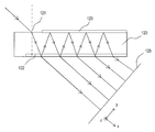
- FIG. 12 shows an optical device disclosed in Patent Document 4.
- the laser beam incident at a predetermined angle from the incident window 121 of the plane-parallel plate 120 is refracted and reflected by the first reflecting surface 122, and then reflected by the second reflecting surface 123, and these first and second reflecting surfaces. Reflection is repeated alternately at 122 and 123.
- the first reflecting surface 122 is partially provided with transmission windows (not shown), and by making the optical path difference of the laser beam transmitted through these transmission windows longer than the coherence distance of the laser light source.
- the light beams transmitted through adjacent transmission windows are incoherent with each other.
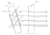
- FIG. 13 shows an optical system of the illumination device disclosed in Patent Document 5.
- the beam splitter 130 is made of a parallel plate with reflection films on both sides of a quartz plate, and the reflectivities of the reflecting surfaces a, b, c, d and e are 75% and 66.5, respectively. %, 50%, 0% and 100%.
- the laser beam is incident on the beam splitter 130, four beams having substantially the same intensity are output. Since the optical path difference of each beam is set larger than the coherence distance, these four beams are incoherent with each other.
- the birefringent crystal 131 arranged at the rear side divides each beam into two beams whose polarizations are perpendicular to each other, and beams having polarizations perpendicular to each other do not interfere with each other. No, ie incoherent.
- Patent Document 6 also discloses a spatial modulation device that modulates light incident from a light source, diffuses light using a diffractive optical element, and reduces speckle by increasing the diffusion angle of light compared to before incidence. A method is disclosed.
- the main object of the present invention is a small optical member (incoherent device) that does not have a mechanical or electrical drive part and can control the light intensity distribution of the outgoing beam, and an optical apparatus using the optical member Is to provide.
- the optical member of the present embodiment is a filter having a total reflection mirror having a reflection surface that reflects a laser beam, and a partial transmission surface that transmits a part of the laser beam and reflects the rest, and the reflection surface; And a filter on which the partial transmission surface is disposed so as to face each other, and a diffraction grating on which the laser beam is incident, diffracts the incident laser beam, and enters the total reflection mirror or the partial transmission filter.
- the size of the beam emitted from the optical member and the distribution of the light intensity in the beam can be freely adjusted by adjusting the grating interval of the diffraction grating and the ratio of the transmittance and the reflectance of the partial transmission filter.
- the optical member can be arranged perpendicular to the incident light. Further, the light emitted from the optical member can be distributed symmetrically with respect to the central axis of the light incident on the optical member. Therefore, downsizing is possible.
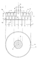
- FIG. 2 is a cross-sectional view and a plan view showing an incoherent device 11 according to Embodiment 1.
- FIG. FIG. 3 is an enlarged cross-sectional view showing an entrance window 15 in the first embodiment.
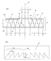
- (A) is sectional drawing which shows the incoherent device 21 of Embodiment 2
- (b) is sectional drawing which expands and shows the entrance window 25 in Embodiment 2.
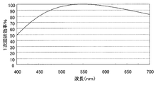
- FIG. It is a graph which shows the result of having calculated the wavelength dependence of the 1st order diffraction efficiency in case a diffraction grating is in contact with air by simulation.
- FIG. (A) to (e) are a sectional view of an incident laser beam and a front view of a diffraction grating shape in an embodiment of the present invention.
- FIG. (A) is sectional drawing and a top view which show the incoherent device of the modification of Embodiment 6
- (b) is sectional drawing which expands and shows the entrance window 105 in the modification of Embodiment 6. It is. It is a schematic block diagram which shows embodiment of the optical apparatus by this invention. It is sectional drawing which shows the conventional optical apparatus disclosed by patent document 4. It is sectional drawing which shows the optical system of the conventional illuminating device disclosed by patent document 5.
- the optical member of the present embodiment is a filter having a total reflection mirror having a reflection surface that reflects a laser beam, and a partial transmission surface that transmits a part of the laser beam and reflects the rest, and the reflection surface; And a filter on which the partial transmission surface is disposed so as to face each other, and a diffraction grating on which the laser beam is incident, diffracts the incident laser beam, and enters the total reflection mirror or the partial transmission filter.
- a transparent member provided between the total reflection mirror and the partial transmission filter may be further provided, and the diffraction grating may be provided on a surface of the transparent member.
- a protective film covering the surface of the diffraction grating may be further provided.
- any one of the material of the diffraction grating and the material of the protective film may have a property that the refractive index is higher and the Abbe number is larger than the other material.
- the diffraction grating and the protective film are made of resin, and inorganic particles may be dispersed in the resin constituting at least one of the diffraction grating and the protective film.
- the protective film may be made of a material in which at least one of zirconium oxide, yttrium oxide, and aluminum oxide is dispersed in a photocurable resin.
- the cross section of the laser beam emitted from the optical member may have an isotropic shape with respect to the center of the cross section.
- the diffraction grating has a ratio of the length of the minor axis to the major axis in the laser beam emitted from the optical member.
- the laser beam may be diffracted so as to be larger than the ratio of the length of the minor axis to the major axis of the laser beam incident on the beam.
- the diffraction grating may have a plurality of sub-regions that diffract in different directions.
- the plurality of diffraction steps may have an elliptical planar shape centered on the same point, and two adjacent ones of the plurality of diffraction steps.
- the interval between the two diffraction steps may be smaller in the minor axis direction of the ellipse than in the major axis direction of the ellipse.
- the total reflection mirror may have an opening for allowing the laser beam to enter the diffraction grating, and the laser beam may be incident perpendicular to the opening.
- the laser beam diffracted by the diffraction grating When the laser beam diffracted by the diffraction grating is incident on the total reflection mirror, the laser beam may be reflected by the total reflection mirror and incident on the partial transmission filter, and is diffracted by the diffraction grating. When the laser beam is incident on the partial transmission filter, a part of the laser beam may pass through the partial transmission filter, and the rest of the laser beam may be transmitted by the partial transmission filter. It may be reflected and incident on the total reflection mirror.
- the cross section of the laser beam emitted from the optical member may be larger than the cross section of the laser beam incident on the optical member.
- the optical apparatus of the present embodiment includes a laser light source, a spatial light modulation element that modulates a laser beam emitted from the laser light source, a projection optical system that projects light modulated by the spatial light modulation element as an image,
- the laser light source may include a red wavelength laser light source, a green wavelength laser light source, and a blue wavelength laser light source.
- Patent Documents 1 and 2 it is necessary to mechanically or electrically drive a lens element or the like. That is, since a complicated mechanism, power supply, and the like are necessary, it is not preferable to apply the inventions of Patent Documents 1 and 2 to devices that require miniaturization and portability.
- the coherence of the incident laser beam is not reduced, it is not effective for applications where it is desired to reduce the condensing property of the laser.
- a retinal scanning display that collects RGB laser light on the human retina and displays a color image
- Patent Document 3 is not suitable for miniaturization because it is necessary to secure a space for the optical fiber bundle. Moreover, since light loss occurs when light enters the optical fiber, the light intensity decreases.
- Patent Documents 4 and 5 incident light is refracted, and in both Patent Document 4 and Patent Document 5, the number of divided outgoing light is about several. In Patent Documents 4 and 5, it is difficult to increase the number of light beams, and these methods have poor expandability and versatility. Moreover, it is not easy to make the intensity distribution of the emitted light symmetrical. Furthermore, since it is necessary to incline the parallel flat plate in Patent Document 4 and the beam splitter in Patent Document 5 with respect to the laser beam, the optical system becomes large and alignment of components is necessary.
- FIG. 1A is a cross-sectional view and a plan view showing Embodiment 1 of an incoherent device according to the present invention.
- the incoherent device 11 of this embodiment includes a total reflection mirror 14, a partial transmission filter 13 that faces the reflection surface, and a diffraction grating 18 that is provided in an incident window 15 of the total reflection mirror 14.
- a transparent substrate 12 having a thickness t is provided between the total reflection mirror 14 and the partial transmission filter 13.
- the total reflection mirror 14, the partial transmission filter 13, and the entrance window 15 each have a circular planar shape.
- the incident window 15 is arranged at a position where the center thereof coincides with the central axis 10 of the laser beam 16.
- the diffraction grating 18 is provided on a portion of the surface of the transparent substrate 12 exposed by the incident window 15.
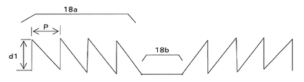
- FIG. 1B is an enlarged cross-sectional view showing the inside of the entrance window 15.
- the diffraction grating 18 disposed inside the incident window 15 includes a concentric blazed diffraction stepped portion 18 a centering on the central axis 10 of the incident window 15 and a flat portion 18 positioned at the center of the incident window 15. .
- the depth of each step in the blazed diffraction step 18a is d1, and the interval between adjacent steps, that is, the pitch is P.
- the step pitch P of the blaze diffraction step portion 18a may be constant or may not be constant. By changing the step pitch P, the cross-sectional intensity distribution of the divergent beam 17 can be changed.
- a laser beam 16 emitted from a light source such as a projector enters the incident window 15 perpendicularly (for example, within 5 degrees from the vertical direction with respect to the incident window) and reaches the diffraction grating 18 in the incident window 15.
- the light incident on the flat portion 18b of the diffraction grating 18 travels straight.
- the light incident on the blaze diffraction step portion 18 a is diffracted and travels in a direction away from the central axis 10 of the incident window 15 (a direction inclined outward by an angle ⁇ from the straight traveling direction) and reaches the partial transmission filter 13. .
- a part of the light passes through the partial transmission filter 13 and is extracted to the outside.
- a part of the light is reflected by the partial transmission filter 13 and enters the total reflection surface 14 a of the total reflection mirror 14.
- the light incident on the total reflection surface 14 a is reflected toward the partial transmission filter 13.
- the light incident on the incoherent device 11 reciprocates inside by being reflected by the partial transmission filter 13 and the total reflection mirror 14.
- a part of the light reaching the partial transmission filter 13 is sequentially transmitted, so that a divergent beam 17 is emitted from the surface opposite to the entrance window 15 in the incoherent device 11.
- the beam diameter (and cross-sectional area) of the diverging beam 17 is the beam diameter of the incident laser beam 16 (and the cross-sectional area). And cross-sectional area).
- the beam diameter of the diverging beam 17 is not necessarily larger than the beam diameter of the incident laser beam 16.
- the cross section of the laser beam 16 emitted from the incoherent device 11 has an isotropic shape (circular shape) with respect to the center of the cross section.
- the angle ⁇ at which light is bent by the blaze diffraction step portion 18a is generally called a diffraction angle and has the following relationship.
- m is the diffraction order
- ⁇ is the wavelength of the incident laser beam 16.
- n1 is the refractive index of the blazed diffraction stepped portion 18a
- n2 is the refractive index of the medium in contact with the blazed diffraction grating.
- the value of n2 is 1.
- the blaze diffraction step 18a is formed integrally with the transparent substrate 12.
- the blaze diffraction step 18a can be formed by a known process such as a semiconductor process such as etching or a mold using a mold.
- the blazed diffraction stepped portion 18a and the transparent base material 12 are not necessarily made of the same material, and may be made of different materials.
- Various optical glasses and various optical resins can be employed as the material of the transparent substrate 12 or the diffraction grating 18.
- the diffracted beam is repeatedly reflected alternately by the partial transmission filter 13 and the total reflection mirror 14, and a part of the diffraction beam passes through the partial transmission filter 13, but is adjacently transmitted.
- the optical path difference ⁇ generated between the beams is expressed by the following equation.
- an incoherent outgoing beam 17 is output. That is, from the relationship of (Equation 2), the order m of the diffracted light that is efficiently diffracted when the depth of the diffraction step in FIG. 1A is d1 is determined, and the optical path is determined by the relationship of (Equation 1) and (Equation 3). The difference ⁇ is determined.
- the optical path difference between adjacent beams is adjusted by adjusting the parameters of the depth d1 of the diffraction step, the pitch P of the diffraction grating, and the thickness t of the transparent substrate. Can be set freely.
- the incoherent device can distribute the intensity of the outgoing beam 17 symmetrically with respect to the central axis 10. Further, since it can be arranged perpendicular to the incident laser beam 26, it is advantageous for miniaturization of the optical system.
- the intensity distribution of the outgoing beam and the size of the beam can be freely designed by setting the value of the ratio between the transmittance and the reflectance of the partial transmission filter 13 and the interval of the step (grating) of the diffraction grating. .
- a general lens optical system is axially symmetric, a beam having an intensity distribution that is axially symmetric with respect to the optical axis can be emitted without using a special optical system. Therefore, it is advantageous for simplification of the optical system.
- the partial transmission filter 13 is composed of, for example, a multilayer film made of two or more kinds of dielectric materials.
- a multilayer film in which titanium oxide and silicon oxide are alternately stacked may be used.
- the total reflection mirror 14 and the incident window 15 of the present embodiment are provided on the plane of the transparent substrate 12, and the partial transmission filter 13 is provided on the plane opposite to this, but if these are curved, the lens action It is also possible to add.
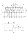
- FIG. 2A is a cross-sectional view showing a second embodiment of the incoherent device according to the present invention.
- the incoherent device 21 of the present embodiment is different from the incoherent device 11 of the first embodiment in that a protective film 29 is provided on the surface of the diffraction grating 28 in the incident window 25.
- Other components are common. Hereinafter, detailed description of the common configuration is omitted.
- FIG. 2B is an enlarged cross-sectional view showing the entrance window 25.
- the diffraction grating 28 disposed inside the incident window 25 has a concentric blazed diffraction stepped portion 28 a centered on the central axis 20 of the incident window 25 and a flat portion 28 b located at the center of the incident window 25. .
- the depth of each step in the blazed diffraction stepped portion 28a is d2, and the interval between adjacent steps, that is, the pitch is P.
- a protective film 29 is provided on the surfaces of the blaze diffraction stepped portion 28 a and the flat portion 28 b in the diffraction grating 28. 2A and 2B, the protective film 29 is provided on the entire surface of the diffraction grating 18, but may be provided only on a part thereof.
- the beam cross section of the laser beam 26 is circular, for example.
- a portion of the laser beam 26 in the vicinity of the central axis 20 travels straight along the central axis 20, but the surrounding beam is diffracted by the concentric diffraction grating and moves away from the central axis 20 (by an angle ⁇ from the straight traveling direction). Proceed in the direction tilted outward).
- Each diffracted beam is repeatedly reflected by the partial transmission filter 23 and the total reflection mirror 24, and a part of the diffracted beam is emitted from the surface opposite to the entrance window 25. Since the diffraction grating 28 of this embodiment diffracts the light incident on the blazed diffraction stepped portion 28a outward, the beam diameter of the divergent beam 27 is larger than the beam diameter of the incident laser beam 126.
- the wavelength dependence of diffraction efficiency can be eliminated by appropriately combining the refractive indexes of the blaze diffraction stepped portion 28a and the protective film 29 and their wavelength dispersion.
- FIG. 3 is a graph showing the results of calculating the wavelength dependence of the first-order diffraction efficiency by simulation.
- the depth of the diffraction step of the diffraction grating set in this calculation is 0.86 ⁇ m.
- the first-order diffraction efficiency shows a high value at a specific wavelength (in the vicinity of a wavelength of 550 nm in FIG. 3), but decreases at a shorter wavelength or a longer wavelength side.
- the decrease in the first-order diffraction efficiency is diffracted light such as 0th order or second order, which is another diffraction order.
- one of the material of the diffraction grating 28 and the material of the protective film 29 has a higher refractive index than the other material, and wavelength dispersion. It is preferable to have a property with low properties (large Abbe number). By having such properties, d that maximizes the first-order diffraction efficiency is constant regardless of the wavelength used.
- Examples of such a combination of materials include a combination of glass and resin, and a combination of a nanocomposite material and a resin in which fine particles of an inorganic material are uniformly dispersed in a resin material.
- a high refractive index and low wavelength dispersion material is used as the diffraction grating 28 (that is, the transparent substrate 22) and a high refractive index and low wavelength dispersion material is used as the protective film 29
- polycarbonate d-line refraction
- a nanocomposite resin d-line refractive index of 1.623, Abbe with a protective film 29 in which zirconium oxide having a particle size of 10 nm or less is dispersed in an acrylic ultraviolet curable resin. Equation 40
- d-line refractive index of 1.623, Abbe with a protective film 29 in which zirconium oxide having a particle size of 10 nm or less is dispersed in an acrylic ultraviolet curable resin. Equation 40 may be used.
- any one of yttrium oxide and aluminum oxide, or a mixture thereof may be used.
- the productivity is high and the weight can be easily reduced.
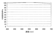
- FIG. 4 is a graph showing the wavelength dependence of the first-order diffraction efficiency when a blazed diffraction grating and a protective film are made of polycarbonate and nanocomposite resin.
- the depth d2 of the diffraction step set in this calculation is 14.9 ⁇ m.
- the incoherent device 21 of the present embodiment exhibits a high first-order diffraction efficiency of 95% or more over the entire visible wavelength range. Similarly, if the depth of the diffraction step is doubled to 29.8 ⁇ m, the diffraction efficiency is uniformly increased over the entire visible wavelength range for the second-order diffracted light and tripled to 44.7 ⁇ m. Is possible.
- the protective film 29 by providing the protective film 29, it is possible to increase the light use efficiency in the three wavelength bands of R, G, and B, that is, the so-called visible wavelength range.
- the diffraction grating 28 is formed integrally with the transparent substrate 22.
- the diffraction grating 28 can be formed by a known process such as a semiconductor process such as etching or a mold using a mold.
- the diffraction grating 28 and the transparent base material 22 are not necessarily made of the same material, and may be made of different materials.
- the incoherent device according to the present embodiment can distribute the intensity of the outgoing beam 27 symmetrically with respect to the central axis 10. Further, since it can be arranged perpendicular to the incident laser beam 26, it is advantageous for miniaturization of the optical system.
- the intensity distribution of the outgoing beam and the beam size can be controlled. Since a general lens optical system is axially symmetric, a beam having an intensity distribution which is axially symmetric with respect to the optical axis can be emitted without using a special optical system. Therefore, it is advantageous for simplification of the optical system.
- the incoherent device of this embodiment since the incoherent device of this embodiment has a high diffraction efficiency regardless of the wavelength in the entire visible wavelength range, it is high with one configuration for all of the incident laser beams 26 of R, G, and B wavelengths. Diffraction efficiency can be obtained.
- the laser beam 26 having wavelengths of R, G, and B can be generated by combining laser beams having wavelengths of R, G, and B with an optical system.
- the total reflection mirror 24 and the incident window 25 of the present embodiment are provided on the plane of the transparent base material 22 and the partial transmission filter 23 is provided on the plane opposite to the transparent base material 22. It is also possible to add.
- FIG. 5A is a cross-sectional view showing Embodiment 3 of the incoherent device according to the present invention.
- the incoherent device 51 of the present embodiment is different from the incoherent device 21 of the second embodiment only in the shape of the diffraction grating 58 in the incident window 55.
- Other components are common. Hereinafter, detailed description of the common configuration is omitted.
- FIG. 5B is an enlarged sectional view showing the incident window 55.
- the diffraction grating 58 disposed inside the incident window 55 includes a flat portion 58B positioned at the center of the incident window 55 and a concentric binary diffraction stepped portion 58A centering on the central axis 50 of the incident window 55.
- the flat portion 58B is the upper surface of the convex portion 58b disposed at the center of the incident window 55, and the planar shape thereof is circular.
- the binary diffraction stepped portion 58A includes a convex portion 58a having a circumferential planar shape centering on the central axis 50 of the incident window 55, and a concave portion 58c between the two convex portions 58a and 58b.
- FIGS. 5A and 5B show a diffraction grating 58 provided with only one circumferential convex portion 58a for the sake of clarity, but there are a plurality of circumferential convex portions 58a. It may be provided.
- either one of the material of the diffraction grating 58 and the material of the protective film 59 has a higher refractive index than that of the other material and a property of low wavelength dispersion. .
- the depth of the diffraction step where the diffraction efficiency of the specific order is maximized is constant regardless of the wavelength used.
- the cross section of the blazed diffraction grating 28 shown in FIG. 2B has a sawtooth shape, and when the depth d of the diffraction step satisfies (Equation 2), the mth-order diffraction efficiency is theoretically 100%.
- a material for a blazed diffraction grating and a protective film are selected such that the value of ⁇ /
- the diffraction grating 58 of the present embodiment shown in FIG. 5B is a binary diffraction grating having an uneven cross section.
- twice the depth d5 of the diffraction step is substituted as d in (Equation 2), and when (Equation 2) is satisfied, theoretically, the first-order and ⁇ 1st-order diffraction efficiencies are about 40%. It becomes.
- the -1st order diffraction is light that diffracts in the opposite direction to the 1st order.
- the solid-line diffracted light 56a (diffracted light diffracted to the left at the diffraction angle ⁇ ′) is the first-order diffracted light
- the broken-line diffracted light 56b (diffracted angle ⁇ ′). (Diffracted light diffracted to the right toward the paper surface) is -1st order diffracted light.
- the first-order and ⁇ 1st-order diffraction efficiencies are constant regardless of the wavelength over the entire visible wavelength range.
- the protective film 59 is not necessarily provided.
- the incoherent device can distribute the intensity of the outgoing beam 57 symmetrically with respect to the central axis 50. Furthermore, since it can be arranged perpendicular to the incident laser beam 56, it is advantageous for miniaturization of the optical system.
- the intensity distribution of the outgoing beam and the size of the beam can be controlled by setting the value of the ratio between the transmittance and the reflectance of the partial transmission filter 53 and the interval of the step (grating) of the diffraction grating. Since a general lens optical system is axially symmetric, a beam having an intensity distribution which is axially symmetric with respect to the optical axis can be emitted without using a special optical system. Therefore, it is advantageous for simplification of the optical system.
- the incoherent device of the present embodiment has the same diffraction efficiency regardless of the wavelength in the entire visible wavelength range, and there is almost no light beam that is diffracted and lost at other orders other than the 0th order.
- High diffraction efficiency can be obtained with one configuration for all of the incident laser beams 56 of the respective wavelengths of.
- the laser beam 26 having wavelengths of R, G, and B can be generated by combining laser beams having wavelengths of R, G, and B with an optical system.
- the total reflection mirror 54 and the incident window 55 of the present embodiment are provided on the plane of the transparent base material 52, and a partial transmission filter 53 is provided on the plane opposite to the transparent base 52. It is also possible to add.
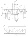
- FIG. 6A is a cross-sectional view showing Embodiment 4 of the incoherent device according to the present invention.
- the incoherent device 61 of this embodiment includes a total reflection mirror 64, an incident window 65 provided in the total reflection mirror 64, a reflective diffractive section 610 provided at a position facing the incident window 65, and total reflection.
- the first partial transmission filter 63 is provided opposite to the mirror 64 and provided adjacent to the reflective diffraction section 610.
- the reflective diffractive portion 610 is in contact with the concentric blazed diffraction step portion 68 and the surface of the blazed diffraction step portion 68 opposite to the surface facing the entrance window 65 (on the light emitting surface side of the incoherent device).
- a second partial transmission filter 611 The first partial transmission filter 63 is provided so as to surround the circumference of the circular reflective diffraction section 610 in plan view.
- the transmissive diffraction grating 18 is provided on the light incident side, but in the present embodiment, the reflective diffractive portion 610 is provided on the light emitting side.
- a transparent substrate 62 having a thickness t is provided between the total reflection mirror 64 and the partial transmission filter 63.
- the central axis 60 of the laser beam 66 incident on the incoherent device 61 coincides with the center of the incident window 65 and the center of the reflection type diffraction unit 610.
- the beam cross section of the laser beam 66 incident perpendicularly to the incident window 65 along the central axis 60 is circular.
- the laser beam 66 travels straight through the transparent substrate 62 and reaches the reflection type diffraction unit 610.
- FIG. 6B is an enlarged cross-sectional view showing the reflection type diffraction portion 610.
- the reflective diffractive portion 610 includes the blazed diffraction stepped portion 68 and the second partial transmission filter 611.
- the depth of each step in the blazed diffraction stepped portion 68 is d6, and the interval between adjacent steps, that is, the pitch is P.
- a protective film 69 is provided on the surface of the reflective diffraction section 610. However, the protective film 69 is not necessarily provided.
- the laser beam 66 that has passed through the transparent substrate 62 passes through the blaze diffraction step portion 68 and reaches the second partial transmission filter 611.
- a part of the laser beam 66 that has reached the second partial transmission filter 611 passes through the second partial transmission filter 611, travels straight, and is emitted to the outside of the incoherent device 61.
- a part of the laser beam 66 that has reached the second partial transmission filter 611 is reflected by the second partial transmission filter 611 and passes through the blazed diffraction grating 68 again.
- the light that has passed through the blazed diffraction grating 68 twice becomes a diffracted beam, and travels in a direction away from the central axis 10 of the incident window 15 (a direction inclined outward from the straight direction by an angle ⁇ ).
- the diffracted beam is repeatedly reflected alternately by the total reflection mirror 64 and the first partial transmission filter 63, and a part of the diffracted beam is transmitted through the first partial transmission filter 63. Since the reflection type diffraction unit 610 of this embodiment diffracts the light incident on the blaze diffraction stepped portion 68 toward the outside, the beam diameter of the diverging beam 67 is larger than the beam diameter of the incident laser beam 66.
- a reflection type diffraction unit 610 is used.
- the depth dr of the diffraction step at which the diffraction efficiency of the diffracted light of the diffraction order m is theoretically 100% is expressed by the following equation.
- n1 is the refractive index of the blazed diffraction grating
- n2 is the refractive index of the medium in contact with the blazed diffraction grating.
- Either one of the material of the blazed diffraction grating 68 and the material of the protective film 69 has a property of having a higher refractive index and lower wavelength dispersion than the other material. By having such a property, the depth of the diffraction step where the diffraction efficiency of the specific order is maximized is constant regardless of the wavelength used. In the present embodiment, detailed description of the same configuration as that of the first or second embodiment will be omitted.
- the incoherent device can distribute the intensity of the outgoing beam 67 symmetrically with respect to the central axis 60. Further, since it can be arranged perpendicular to the incident laser beam 66, it is advantageous for miniaturization of the optical system.
- the intensity distribution of the outgoing beam and the size of the beam are set. Can be controlled. Since a general lens optical system is axially symmetric, a beam having an intensity distribution which is axially symmetric with respect to the optical axis can be emitted without using a special optical system. Therefore, it is advantageous for simplification of the optical system.
- the incoherent device of this embodiment since the incoherent device of this embodiment has a high diffraction efficiency regardless of the wavelength in the entire visible wavelength range, it is high with one configuration for all of the incident laser beams 66 of the R, G, and B wavelengths. Diffraction efficiency can be obtained.
- the laser beam 66 having R, G, and B wavelengths can be generated by combining laser beams having R, G, and B wavelengths with an optical system.
- the total reflection mirror 64 and the incident window 65 are provided on the plane of the transparent base material 62, and the reflection type diffractive portion 610 and the first partial transmission filter 63 are provided on the plane opposite to this.
- the reflection type diffractive portion 610 and the first partial transmission filter 63 are provided on the plane opposite to this.
- a lens action can be added.
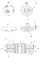
- FIG. 7A shows an incident laser beam having a circular cross-sectional shape.
- Such an incident laser beam has a circular cross section by using the diffraction grating used in the first to fourth embodiments, that is, the concentric diffraction grating 78 as shown in FIG. 7B.
- An outgoing beam can be emitted.
- the beam emitted from the end face reflects the shape of the active layer and greatly spreads in a direction perpendicular to the thickness direction of the active layer. That is, the far field cross section of the beam emitted from the end face of the active layer has an elliptical shape as shown in FIG.
- a beam shaping optical system is required, and an increase in the number of parts and an increase in the size of the optical system are inevitable.
- the diffraction grating 88 shown in FIG. 7D has a flat part 88b located at the center of the diffraction grating 88 and a diffraction step part 88a located outside the flat part 88b.
- the diffraction stepped portion 88a has a plurality of annular zones (regions between two adjacent diffraction steps) 88c, 88d, 88e, and 88f, and the width of each annular zone in the minor axis direction (vertical direction toward the paper surface).
- the (interval between the two diffraction steps) is made smaller than the width (interval between the two diffraction steps) in the major axis direction (the left-right direction toward the paper surface) in the annular zone.
- the width Ps in the minor axis direction of the annular zone 88e is smaller than the width Pl in the major axis direction.
- Equation 1 As the diffraction step pitch decreases, the diffraction angle ⁇ increases. Therefore, the cross section of the laser beam is stretched more greatly in the direction in which the diffraction step pitch is relatively small. Therefore, when the diffraction grating 88 as shown in FIG.
- the emitted laser beam is closer to a circle than the incident laser beam.
- the sectional shape of the outgoing beam is formed into a circular shape by adjusting the pitch ratio of the diffraction step in the major axis direction and the minor axis direction of the ellipse according to the sectional shape of the incident laser beam 86. can do.
- FIG. 8 shows an incoherent device 81 of the present embodiment.
- the incoherent device 81 shown in FIG. 8 not only the diffraction grating 88 but also the entrance window 85 has an elliptical planar shape centered on the central axis 80.
- the incident window 85 may have any planar shape as long as the laser beam 86 can be incident as a whole. Since the short axis side of the laser beam 86 is stretched by the diffraction grating 88, the total reflection mirror 84 and the partial transmission filter 83 may have a circular planar shape centering on the central axis 80 of the incident laser beam 86.
- the second embodiment is the same as the second embodiment, and a detailed description thereof will be omitted.
- the diffraction grating pattern is not limited to a concentric circle shape or an elliptical shape.
- the diffraction grating 70 is divided into a plurality of sub-regions, and the shape of the incident laser beam. It is also possible to change the pitch and arrangement direction of the diffraction grating shape of each sub-region according to the intensity distribution.
- the diffraction grating 70 shown in FIG. 7E has a central portion 70a and side portions 70b arranged on both sides of the central portion 70a as sub-regions.
- the central portion 70a and the side portion 70b each have a plurality of diffraction steps 74.
- the side portion 70b is divided into a first side portion 70b1 and a second side portion 70b2 depending on the direction of the diffraction step 74.
- the incident laser beam has an elliptical cross section, for example, the laser beam is incident so that the long axis direction of the laser beam coincides with the long side direction of the diffraction grating 70.
- the laser beam is incident perpendicular to the surface of the diffraction grating 70 on which the diffraction grating is provided. In this case, the laser beam is diffracted in a direction perpendicular to the diffraction step of each region.
- the laser beam is diffracted in the direction A (the short side direction of the diffraction grating 70).
- the laser beam is diffracted in the direction B1 and the direction B2, respectively.
- the directions B1 and B2 are directions inclined from the short side and long side directions of the diffraction grating 70.
- the shape of the light emitted from the incoherent device is adjusted by providing multiple sub-regions that guide the laser beam in different directions in the diffraction grating and adjusting the area of each sub-region and the gap between the diffraction steps. can do.
- the ratio of the length of the short axis to the long axis of the laser beam emitted from the incoherent device is relative to the long axis of the laser beam incident on the diffraction grating.
- the laser beam can be diffracted to be larger than the ratio of the minor axis lengths.
- FIGS. 7D and 7E can be applied to any of the first to fourth embodiments.
- the present embodiment having not only the incoherence of the laser beam but also the function of simultaneously shaping the laser beam is very useful.
- the beam is refracted in the device and emitted toward the surface 125 by tilting the incident beam with respect to the normal of the incident surface of the device.
- the surface 125 is a surface parallel to the yz plane.
- the width of the cross section of the beam formed on the surface 125 in the y direction becomes wider than the width of the beam incident on the device in the y direction.
- the width in the z direction of the cross section of the beam formed on the surface 125 is considered to be substantially the same as the width in the z direction of the beam incident on the device.
- the optical path length difference can be changed only by changing the thickness t of the device. As described above, it is difficult to change the layout in the device shown in FIG.
- the incident beam incident parallel to the normal of the incident surface of the device is diffracted by the diffraction grating, and the cross section of the outgoing beam is wider than the cross section of the incident beam.
- the pitch of the steps of the diffraction grating is set as shown in FIG.
- the cross section of the laser beam having an elliptical cross section can be corrected to a circle.
- the diffraction grating shown in FIG. 7E can be corrected.
- FIG. 7E by changing the direction in which the diffraction step is formed for each partial region, the direction in which light is bent can be changed for each partial region.
- the output beam is made circular by increasing the area ratio of the diffraction grating pattern region bent in this direction so that the beam is further expanded in the minor axis direction. can do.
- the diffraction grating according to the present embodiment has an advantage that the degree of freedom in layout is high. According to the diffraction grating in the present embodiment, it is possible to control the beam shape and the coherence without changing the device size.
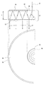
- FIG. 9A is a sectional view showing Embodiment 6 of the incoherent device according to the present invention.
- the incoherent device 91 of this embodiment has a semicircular planar shape.
- the diffraction grating 98, the total reflection mirror 94, and the partial transmission filter 93 have a semicircular planar shape centered on the same point. Since other configurations are the same as those of the first embodiment, detailed description thereof is omitted.
- the diffraction grating 98 has a plurality of diffraction steps, the height of each step is d1, and the pitch of each step is P.
- the present embodiment not only the first embodiment but also a part of any incoherent device of the second to fifth embodiments may be used.
- the planar shape of the incoherent device 9 of the present embodiment is a semicircular shape, but may have another shape (for example, a straight line shape).
- FIG. 10A is a cross-sectional view showing a modification of the sixth embodiment
- FIG. 10B is an enlarged view of the diffraction grating 108 of FIG. 10A
- the incoherent device 101 of this modification has a configuration in which the positions of the total reflection mirror 94 and the partial transmission filter 93 in the incoherent device 91 described above are interchanged. That is, the partial transmission filter 103 is provided on the side where the laser beam 100 is incident in the incoherent device 101.
- the partial transmission filter 103 is provided with an incident window 105, and a diffraction grating 108 is disposed in the incident window 105.
- the laser beam 100 incident on the incident window 105 is diffracted by the diffraction grating 108 to become a diffracted beam, and reaches the total reflection mirror 104.
- the diffracted beam is repeatedly reflected alternately by the partial transmission filter 103 and the total reflection mirror 104, and a part of the diffracted beam is emitted from the partial transmission filter 103.
- the divergent beam 107 is emitted from the same surface as the surface on which the laser beam 100 is incident.
- the direction in which the divergent beam 107 is emitted is often different from the direction in which the laser beam 100 is incident.
- a divergent beam may be emitted from a surface on the same side as the surface on which the laser beam has entered, as in this modification.
- the light use efficiency is high, the light intensity distribution of the outgoing beam can be easily controlled with a small size.
- FIG. 11 is a schematic configuration diagram showing an embodiment of an optical device according to the present invention.
- the optical device of the present embodiment is an optical device that projects an image on a screen, and includes the incoherent device 111 of Embodiments 1 to 6 in the optical system.
- the operation of the present optical apparatus will be described.
- the blue wavelength laser light emitted from the blue wavelength laser light source 112 is reflected by the mirror 115, and the red wavelength laser light and the green wavelength laser light emitted from the red wavelength laser light source 113 and the green wavelength laser light source are respectively color separation filters 116,. 117 is reflected in a wavelength selective manner.
- the laser beams are combined on the same optical axis and enter the incoherent device 111.
- the beam output from the incoherent device 111 enters the lens optical system 118, and the lens optical system 118 makes the beam intensity uniform and adjusts the beam size. Thereafter, the beam reaches the polarization beam splitter 119.
- the polarizing beam splitter 119 is an optical element that reflects almost 100% of S-polarized light (polarized light perpendicular to the paper surface) and transmits almost 100% of P-polarized light (polarized light in the paper surface) over the entire visible wavelength range.
- S-polarized laser beams are emitted from the blue wavelength laser light source 112, the red wavelength laser light source 113, and the green wavelength laser light source 114, and the S-polarized light is also maintained in the incoherent device 111.
- the light reflected by the polarization beam splitter reaches the spatial light modulator 1110. This is made up of a reflective liquid crystal panel and applies RGB image information to each laser beam of blue wavelength, red wavelength and green wavelength.
- the light modulated in this way by the spatial light modulator 1110 is simultaneously converted from S-polarized light to P-polarized light, reaches the polarization beam splitter 119 again, passes through it, and then is projected onto the screen 1112 by the projection lens optical system 1111. Project.
- the incoherent device 111 shown in FIG. 1A was used.
- the step d1 of the diffraction grating was 1.76 ⁇ m
- the pitch P of the diffraction grating was 8 ⁇ m
- the diffraction order was secondary.
- the outgoing laser beam can be made incoherent by setting the optical path difference between adjacent light beams to be several hundred ⁇ m larger than the wavelength of light emitted from each laser light source.
- the incoherent device 111 is inserted, and the spatial light modulator 1110 is driven again to display an image on the screen 1112.
- speckle noise has a luminance fluctuation of about 5% at maximum.
- the speckle noise level has been reduced to almost no problem even with visual observation.
- the spec of the incoherent device may be determined according to the wavelength width of the laser light source.
- the optical device of the present invention uses a laser as a light source, an image having an illuminance several times that of an LED light source can be obtained, and a special mechanical and electrical driving element is used. Speckle noise can be reduced.
- the incoherent device of the first embodiment is used.
- an incoherent device such as the second embodiment since it has high light efficiency in the entire visible wavelength range, it is brighter and clearer. An optical device that displays a clear image becomes possible.
- the incoherent device of the embodiment reduces not only the speckle noise reduction effect but also the coherence of the laser beam, thereby reducing the laser focusing spot. It has the effect of reducing the strength at.
- the incoherent device of the embodiment can also be applied to a head-mounted display that scans RGB lasers on a human retina and displays an image on the retina. In this case, it is possible to utilize the characteristics of the incoherent device of the embodiment that is small and does not have mechanical and electrical driving elements, and a compact optical device can be realized.
- the transparent substrate is not necessarily provided.
- a diffractive lens may be provided in the incident window, and air may be provided between the partial transmission filter and the total reflection mirror.
- a member for fixing the positional relationship between the partial transmission filter and the total reflection mirror is required.
- the incoherent device of the present invention can be used in applications for projecting and displaying bright images and videos, particularly in portable projectors and displays.
Landscapes
- Physics & Mathematics (AREA)
- General Physics & Mathematics (AREA)
- Optics & Photonics (AREA)
- Diffracting Gratings Or Hologram Optical Elements (AREA)
- Projection Apparatus (AREA)
Abstract
Description
本発明の主な目的は、機械的、あるいは電気的な駆動部分を持たず、小型で出射ビームの光強度分布の制御が可能な光学部材(インコヒーレント化デバイス)、およびこれを用いた光学機器を提供することにある。
図1Aは、本発明によるインコヒーレント化デバイスの実施の形態1を示す断面図および平面図である。本実施形態のインコヒーレント化デバイス11は、全反射ミラー14と、前記反射面と対向する部分透過フィルター13と、全反射ミラー14の入射窓15に設けられた回折格子18とを備える。全反射ミラー14と部分透過フィルター13との間には厚さtの透明基板12が設けられている。



図2(a)は、本発明によるインコヒーレント化デバイスの実施の形態2を示す断面図である。本実施形態のインコヒーレント化デバイス21において実施の形態1のインコヒーレント化デバイス11と異なるのは、入射窓25内の回折格子28の表面に保護膜29が設けられている点である。その他の構成要素は共通である。以下では、共通の構成についての詳細な説明は省略する。
図5(a)は、本発明によるインコヒーレント化デバイスの実施の形態3を示す断面図である。本実施形態のインコヒーレント化デバイス51において実施の形態2のインコヒーレント化デバイス21と異なるのは、入射窓55内の回折格子58の形状のみである。その他の構成要素は共通である。以下では、共通の構成についての詳細な説明は省略する。
図6(a)は、本発明によるインコヒーレント化デバイスの実施の形態4を示す断面図である。本実施形態のインコヒーレント化デバイス61は、全反射ミラー64と、全反射ミラー64に設けられた入射窓65と、入射窓65に対向する位置に設けられた反射型回折部610と、全反射ミラー64に対向し、反射型回折部610に隣接して設けられた第1の部分透過フィルター63とを備える。反射型回折部610は、同心円状のブレーズ回折段差部68と、ブレーズ回折段差部68のうち入射窓65に対向する面とは反対側の面(インコヒーレント化デバイスの光出射面側)に接する第2の部分透過フィルター611とを有する。第1の部分透過フィルター63は、平面視して、円形の反射型回折部610の周囲を囲むように設けられている。

実施の形態1から4では、ビーム断面形状が円形の場合を対象としていたが、以下では、ビーム断面形状や強度分布が非軸対称である入射レーザービームを対象にしたインコヒーレント化デバイスを説明する。
図9Aは、本発明によるインコヒーレント化デバイスの実施の形態6を示す断面図である。本実施形態のインコヒーレント化デバイス91は、半円形の平面形状を有する。回折格子98、全反射ミラー94および部分透過フィルター93は同じ点を中心とする半円の平面形状を有する。他の構成は実施の形態1と同様であるため、その詳細な説明は省略する。図9Bに示すように、回折格子98は複数の回折段差を有し、それぞれの段差の高さはd1であり、それぞれの段差のピッチはPである。本実施形態においては、実施の形態1だけではなく、実施の形態2から5のいずれのインコヒーレント化デバイスの一部を用いてもよい。
図11は、本発明による光学装置の実施形態を示す概略構成図である。本実施形態の光学装置は、スクリーンに画像を投射する光学装置であり、実施の形態1~6のインコヒーレント化デバイス111を光学系内に備えている。以下、本光学装置の動作について説明する。
11,21,51,61,81,91,101 インコヒーレント化デバイス
12,22,52,62,82,92,102 透明基材
13,23,53,63,611,83,93,103 部分透過フィルター
14,24,54,64,84,94,104 全反射ミラー
15,25,55,65,85,95,105 入射窓
16,26,56,66,86,90,100 入射レーザービーム
17,27,57,67,87,97,107 出射レーザービーム
18a,28a,68,88,98,108 ブレーズ回折格子
18b、28b,78b,708b 平坦部
29,59,69 保護膜
58 バイナリー回折格子
610 反射型回折部
78a 同心円状の回折格子
708a 楕円形状の回折格子
112 青波長レーザー光源
113 赤波長レーザー光源
114 緑波長レーザー光源
115 ミラー
116,117 色分離フィルター
118 レンズ光学系
119 偏光ビームスプリッタ
1110 空間光変調器
1111 投射レンズ光学系
1112 スクリーン
120 平行平面板
122,123 反射面
130 ビーム分割器
131 複屈折結晶
Claims (15)
- レーザービームを反射する反射面を有する全反射ミラーと、
前記レーザービームの一部を透過し、残りを反射する部分透過面を有するフィルターであって、前記反射面と対向するように前記部分透過面が配置されるフィルターと、
前記レーザービームが入射し、前記入射したレーザービームを回折させ、前記全反射ミラーまたは前記部分透過フィルターに入射させる回折格子と、
を備える、光学部材。 - 前記全反射ミラーと前記部分透過フィルターとの間に設けられた透明部材をさらに備え、前記回折格子は前記透明部材の表面に設けられている、請求項1に記載の光学部材。
- 前記回折格子の表面を覆う保護膜をさらに備える、請求項1または2に記載の光学部材。
- 前記回折格子の材料と前記保護膜の材料とのうち、いずれか一方の材料は、他方の材料よりも屈折率が高く、かつアッベ数が大きい性質を有する、請求項3に記載の光学部材。
- 前記回折格子および前記保護膜は樹脂からなり、前記回折格子および前記保護膜のうちの少なくともいずれか一方を構成する樹脂には、無機粒子が分散している、請求項3または4に記載の光学部材。
- 前記保護膜は、光硬化樹脂に酸化ジルコニウム、酸化イットリウムおよび酸化アルミニウムのうちの少なくともいずれか1つの粒子を分散した材料からなる、請求項3から5のいずれかに記載の光学部材。
- 前記光学部材から出射される前記レーザービームの断面は、前記断面の中心に対して等方的な形状を有する、請求項1から6のいずれかに記載の光学部材。
- 前記レーザービームの断面が長軸および短軸を有し、
前記回折格子は、前記光学部材から出射する前記レーザービームにおける前記長軸に対する前記短軸の長さの比が、前記回折格子に入射する前記レーザービームにおける前記長軸に対する前記短軸の長さの比よりも大きくなるように、前記レーザービームを回折する、請求項1から7のいずれかに記載の光学部材。 - 前記回折格子はそれぞれ異なる方向に回折する複数のサブ領域を有する、請求項1から8のいずれかに記載の光学部材。
- 前記回折格子は、複数の回折段差を有し、
前記複数の回折段差は、同じ点を中心とする楕円の平面形状を有し、
前記複数の回折段差のうち隣り合う2つの回折段差の間隔は、前記楕円の長軸方向よりも前記楕円の短軸方向において小さい、請求項1から9のいずれかに記載の光学部材。 - 前記全反射ミラーは、前記レーザービームを前記回折格子に入射させるための開口を有し、
前記レーザービームは、前記開口に対して垂直に入射する、請求項1から10のいずれかに記載の光学部材。 - 前記回折格子によって回折された前記レーザービームが前記全反射ミラーに入射した場合には、前記レーザービームは前記全反射ミラーによって反射されて前記部分透過フィルターに入射し、
前記回折格子によって回折された前記レーザービームが前記部分透過フィルターに入射した場合には、前記レーザービームのうちの一部が前記部分透過フィルターを透過し、前記レーザービームのうちの残りが前記部分透過フィルターによって反射されて前記全反射ミラーに入射する、請求項1から11のいずれかに記載の光学部材。 - 前記光学部材から出射される前記レーザービームの断面は、前記光学部材に入射する前記レーザービームの断面より大きい、請求項1から12のいずれかに記載の光学部材。
- レーザー光源と、
前記レーザー光源から出射されたレーザービームを変調する空間光変調素子と、
前記空間光変調素子で変調された光を画像として投射する投射光学系と、
前記レーザー光源と前記空間光変調素子との間に配置される請求項1から12のいずれかに記載の光学部材と
を備える光学装置。 - 前記レーザー光源は、赤波長レーザー光源、緑波長レーザー光源および青波長レーザー光源を含む、請求項14に記載の光学装置。
Priority Applications (3)
| Application Number | Priority Date | Filing Date | Title |
|---|---|---|---|
| CN2012800014484A CN102918431A (zh) | 2011-04-12 | 2012-04-02 | 非相干化器件和使用它的光学装置 |
| JP2013509755A JP5528623B2 (ja) | 2011-04-12 | 2012-04-02 | インコヒーレント化デバイス、およびこれを用いた光学装置 |
| US13/699,798 US8870383B2 (en) | 2011-04-12 | 2012-04-02 | Incoherence device and optical apparatus using same |
Applications Claiming Priority (2)
| Application Number | Priority Date | Filing Date | Title |
|---|---|---|---|
| JP2011088505 | 2011-04-12 | ||
| JP2011-088505 | 2011-04-12 |
Publications (1)
| Publication Number | Publication Date |
|---|---|
| WO2012140845A1 true WO2012140845A1 (ja) | 2012-10-18 |
Family
ID=47009040
Family Applications (1)
| Application Number | Title | Priority Date | Filing Date |
|---|---|---|---|
| PCT/JP2012/002293 Ceased WO2012140845A1 (ja) | 2011-04-12 | 2012-04-02 | インコヒーレント化デバイス、およびこれを用いた光学装置 |
Country Status (4)
| Country | Link |
|---|---|
| US (1) | US8870383B2 (ja) |
| JP (1) | JP5528623B2 (ja) |
| CN (1) | CN102918431A (ja) |
| WO (1) | WO2012140845A1 (ja) |
Cited By (6)
| Publication number | Priority date | Publication date | Assignee | Title |
|---|---|---|---|---|
| JP2016051072A (ja) * | 2014-08-29 | 2016-04-11 | 日亜化学工業株式会社 | 光源装置及び該光源装置を備えたプロジェクタ |
| JP2016062011A (ja) * | 2014-09-19 | 2016-04-25 | 株式会社島津製作所 | 可干渉性低減素子 |
| JP2016071128A (ja) * | 2014-09-30 | 2016-05-09 | セイコーエプソン株式会社 | 光源装置およびプロジェクター |
| JP2017067936A (ja) * | 2015-09-29 | 2017-04-06 | 株式会社Jvcケンウッド | 光源装置及び画像投射装置 |
| JP2017090562A (ja) * | 2015-11-05 | 2017-05-25 | セイコーエプソン株式会社 | 光束径拡大素子および表示装置 |
| WO2021251332A1 (ja) * | 2020-06-09 | 2021-12-16 | 株式会社小糸製作所 | 光学素子および画像投影装置 |
Families Citing this family (10)
| Publication number | Priority date | Publication date | Assignee | Title |
|---|---|---|---|---|
| US10095016B2 (en) | 2011-01-04 | 2018-10-09 | Nlight, Inc. | High power laser system |
| US9049413B2 (en) | 2013-07-30 | 2015-06-02 | Dolby Laboratories Licensing Corporation | Multiple stage modulation projector display systems having efficient light utilization |
| JP6286546B2 (ja) | 2013-07-30 | 2018-02-28 | ドルビー ラボラトリーズ ライセンシング コーポレイション | 非機械的ミラービームステアリングを備えたプロジェクタ表示システム |
| US9709810B2 (en) * | 2014-02-05 | 2017-07-18 | Nlight, Inc. | Single-emitter line beam system |
| US10162181B2 (en) * | 2015-12-03 | 2018-12-25 | Microsoft Technology Licensing, Llc | Display device with optics for brightness uniformity tuning having DOE optically coupled to receive light at central and peripheral regions |
| JP6778856B2 (ja) * | 2016-03-25 | 2020-11-04 | パナソニックIpマネジメント株式会社 | ミラーパネル、ミラーフィルム及び表示システム |
| CN111906094B (zh) * | 2020-07-29 | 2022-09-20 | 中国南方电网有限责任公司超高压输电公司柳州局 | 一种激光清洗剂除锈环形接头装置 |
| CN111751312B (zh) * | 2020-08-18 | 2023-08-08 | 杭州谱析光晶半导体科技有限公司 | 一种基于光场重构器件的室内空气质量监测系统及方法 |
| CN112130336A (zh) * | 2020-09-27 | 2020-12-25 | 欧菲微电子技术有限公司 | 光学组件、3d感测组件以及电子设备 |
| CN113900268B (zh) * | 2021-10-19 | 2023-05-09 | 山西大学 | 一种散斑抑制装置及制作方法 |
Citations (5)
| Publication number | Priority date | Publication date | Assignee | Title |
|---|---|---|---|---|
| JPH0961610A (ja) * | 1994-10-31 | 1997-03-07 | Nippon Steel Corp | バイナリーオプティクス及びそれを用いた集光光学系並びにレーザ加工装置 |
| JP2001059905A (ja) * | 1999-06-16 | 2001-03-06 | Matsushita Electronics Industry Corp | 回折型光学素子および当該回折型光学素子を用いた光ピックアップ |
| JP2006267284A (ja) * | 2005-03-22 | 2006-10-05 | Fuji Xerox Co Ltd | 回折光学レンズ、及びそれを用いた光ビームのモードプロファイルの変換方法、光学デバイスの接続方法、並びに光学デバイスのピッチ変換方法 |
| JP2008152019A (ja) * | 2006-12-18 | 2008-07-03 | Seiko Epson Corp | 光源装置、画像表示装置、プロジェクタ、照明装置、及びモニタ装置 |
| JP4630393B2 (ja) * | 2008-12-26 | 2011-02-09 | パナソニック株式会社 | 回折レンズ、およびこれを用いた撮像装置 |
Family Cites Families (17)
| Publication number | Priority date | Publication date | Assignee | Title |
|---|---|---|---|---|
| JPS61248001A (ja) | 1985-04-26 | 1986-11-05 | Toshiba Corp | グレ−デイングレンズ |
| JPS63211624A (ja) | 1987-02-26 | 1988-09-02 | Komatsu Ltd | 照明光学装置 |
| JPS63216338A (ja) | 1987-03-05 | 1988-09-08 | Komatsu Ltd | 照明光学装置 |
| JP2526986B2 (ja) | 1988-05-18 | 1996-08-21 | 株式会社ニコン | 照明装置 |
| JP2590530B2 (ja) | 1988-05-20 | 1997-03-12 | 株式会社ニコン | 光学装置 |
| JPH06167640A (ja) | 1991-10-03 | 1994-06-14 | Senri Oyo Keisoku Kenkyusho:Kk | レーザー光照明装置 |
| US6728034B1 (en) | 1999-06-16 | 2004-04-27 | Matsushita Electric Industrial Co., Ltd. | Diffractive optical element that polarizes light and an optical pickup using the same |
| JP2002116404A (ja) * | 2000-10-05 | 2002-04-19 | Olympus Optical Co Ltd | 3次元偏心光路を備えた画像表示装置 |
| JP2002267825A (ja) | 2001-03-09 | 2002-09-18 | Sony Corp | 回折型レンズ素子及びこれを用いた照明装置 |
| JP4475501B2 (ja) * | 2003-10-09 | 2010-06-09 | インターナショナル・ビジネス・マシーンズ・コーポレーション | 分光素子、回折格子、複合回折格子、カラー表示装置、および分波器 |
| US7775666B2 (en) * | 2005-03-16 | 2010-08-17 | Panasonic Corporation | Three-dimensional image communication terminal and projection-type three-dimensional image display apparatus |
| JP4810949B2 (ja) | 2005-09-29 | 2011-11-09 | ソニー株式会社 | 光学装置及び画像表示装置 |
| US8845109B2 (en) * | 2007-11-24 | 2014-09-30 | Yong-Jing Wang | Projection system based on self emitting display panel |
| DE602009000115D1 (de) | 2008-04-15 | 2010-09-30 | Jds Uniphase Corp | Auf einem Wellenlängenplättchen basierende Vorrichtung und Methode zur Reduzierung von Speckles in Laserbeleuchtungssystemen |
| JP5380943B2 (ja) | 2008-08-04 | 2014-01-08 | セイコーエプソン株式会社 | プロジェクタ |
| JP5251702B2 (ja) | 2009-04-24 | 2013-07-31 | ソニー株式会社 | Da変換装置、固体撮像素子、およびカメラシステム |
| JP5953835B2 (ja) * | 2011-09-07 | 2016-07-20 | セイコーエプソン株式会社 | プロジェクター |
-
2012
- 2012-04-02 WO PCT/JP2012/002293 patent/WO2012140845A1/ja not_active Ceased
- 2012-04-02 JP JP2013509755A patent/JP5528623B2/ja active Active
- 2012-04-02 CN CN2012800014484A patent/CN102918431A/zh active Pending
- 2012-04-02 US US13/699,798 patent/US8870383B2/en active Active
Patent Citations (5)
| Publication number | Priority date | Publication date | Assignee | Title |
|---|---|---|---|---|
| JPH0961610A (ja) * | 1994-10-31 | 1997-03-07 | Nippon Steel Corp | バイナリーオプティクス及びそれを用いた集光光学系並びにレーザ加工装置 |
| JP2001059905A (ja) * | 1999-06-16 | 2001-03-06 | Matsushita Electronics Industry Corp | 回折型光学素子および当該回折型光学素子を用いた光ピックアップ |
| JP2006267284A (ja) * | 2005-03-22 | 2006-10-05 | Fuji Xerox Co Ltd | 回折光学レンズ、及びそれを用いた光ビームのモードプロファイルの変換方法、光学デバイスの接続方法、並びに光学デバイスのピッチ変換方法 |
| JP2008152019A (ja) * | 2006-12-18 | 2008-07-03 | Seiko Epson Corp | 光源装置、画像表示装置、プロジェクタ、照明装置、及びモニタ装置 |
| JP4630393B2 (ja) * | 2008-12-26 | 2011-02-09 | パナソニック株式会社 | 回折レンズ、およびこれを用いた撮像装置 |
Cited By (8)
| Publication number | Priority date | Publication date | Assignee | Title |
|---|---|---|---|---|
| JP2016051072A (ja) * | 2014-08-29 | 2016-04-11 | 日亜化学工業株式会社 | 光源装置及び該光源装置を備えたプロジェクタ |
| JP2016062011A (ja) * | 2014-09-19 | 2016-04-25 | 株式会社島津製作所 | 可干渉性低減素子 |
| JP2016071128A (ja) * | 2014-09-30 | 2016-05-09 | セイコーエプソン株式会社 | 光源装置およびプロジェクター |
| JP2017067936A (ja) * | 2015-09-29 | 2017-04-06 | 株式会社Jvcケンウッド | 光源装置及び画像投射装置 |
| JP2017090562A (ja) * | 2015-11-05 | 2017-05-25 | セイコーエプソン株式会社 | 光束径拡大素子および表示装置 |
| WO2021251332A1 (ja) * | 2020-06-09 | 2021-12-16 | 株式会社小糸製作所 | 光学素子および画像投影装置 |
| JP2021196399A (ja) * | 2020-06-09 | 2021-12-27 | 株式会社小糸製作所 | 光学素子および画像投影装置 |
| JP7479945B2 (ja) | 2020-06-09 | 2024-05-09 | 株式会社小糸製作所 | 光学素子および画像投影装置 |
Also Published As
| Publication number | Publication date |
|---|---|
| CN102918431A (zh) | 2013-02-06 |
| JPWO2012140845A1 (ja) | 2014-07-28 |
| JP5528623B2 (ja) | 2014-06-25 |
| US20130070207A1 (en) | 2013-03-21 |
| US8870383B2 (en) | 2014-10-28 |
Similar Documents
| Publication | Publication Date | Title |
|---|---|---|
| JP5528623B2 (ja) | インコヒーレント化デバイス、およびこれを用いた光学装置 | |
| CN108369300B (zh) | 使用具有相应不同的发射峰值的多个不同的窄带光进行成像的系统和方法 | |
| CN102608762B (zh) | 图像显示装置 | |
| US8562152B2 (en) | Collimator lens unit with aspheric surfaces for imparting a luminous flux density distribution | |
| JP5884743B2 (ja) | 照明装置および表示装置 | |
| US10228573B2 (en) | Projection device and projection-type video display device | |
| US20110109528A1 (en) | Wearable display apparatus | |
| JP6000303B2 (ja) | 表示モジュール | |
| JP2009151221A (ja) | 照明装置、画像表示装置及び偏光変換拡散部材 | |
| JP2004038012A (ja) | 映像表示装置 | |
| WO2011043208A1 (ja) | 光学素子、光源装置、及び投射型表示装置 | |
| JP2007121899A (ja) | 光路合成装置および光ビーム合成方法 | |
| US20080192501A1 (en) | System and method for displaying images | |
| KR20240032940A (ko) | 증강현실 장치 | |
| US12429629B2 (en) | Projector | |
| CN107728243B (zh) | 一种无色散偏振复用光栅及显示装置 | |
| KR20160022855A (ko) | 착용형 디스플레이장치 | |
| JP5024859B2 (ja) | 画像表示装置 | |
| JP2015102866A (ja) | 光源装置および投射装置 | |
| JP5741445B2 (ja) | 照明装置およびそれを用いた投射型表示装置 | |
| CN112305661A (zh) | 光学元件和图像显示装置 | |
| JP2006017931A (ja) | 画像表示装置 | |
| JP6179421B2 (ja) | 光源装置および投射装置 | |
| JP5429343B2 (ja) | 画像表示装置 | |
| JP6194967B2 (ja) | 照明装置および表示装置 |
Legal Events
| Date | Code | Title | Description |
|---|---|---|---|
| WWE | Wipo information: entry into national phase |
Ref document number: 201280001448.4 Country of ref document: CN |
|
| ENP | Entry into the national phase |
Ref document number: 2013509755 Country of ref document: JP Kind code of ref document: A |
|
| WWE | Wipo information: entry into national phase |
Ref document number: 13699798 Country of ref document: US |
|
| 121 | Ep: the epo has been informed by wipo that ep was designated in this application |
Ref document number: 12771113 Country of ref document: EP Kind code of ref document: A1 |
|
| NENP | Non-entry into the national phase |
Ref country code: DE |
|
| 122 | Ep: pct application non-entry in european phase |
Ref document number: 12771113 Country of ref document: EP Kind code of ref document: A1 |