WO2012144394A1 - 照明装置、及びそれを備えた照明機器 - Google Patents
照明装置、及びそれを備えた照明機器 Download PDFInfo
- Publication number
- WO2012144394A1 WO2012144394A1 PCT/JP2012/059939 JP2012059939W WO2012144394A1 WO 2012144394 A1 WO2012144394 A1 WO 2012144394A1 JP 2012059939 W JP2012059939 W JP 2012059939W WO 2012144394 A1 WO2012144394 A1 WO 2012144394A1
- Authority
- WO
- WIPO (PCT)
- Prior art keywords
- light
- guide plate
- light guide
- light emitting
- light source
- Prior art date
- Legal status (The legal status is an assumption and is not a legal conclusion. Google has not performed a legal analysis and makes no representation as to the accuracy of the status listed.)
- Ceased
Links
Images


Classifications
-
- F—MECHANICAL ENGINEERING; LIGHTING; HEATING; WEAPONS; BLASTING
- F21—LIGHTING
- F21S—NON-PORTABLE LIGHTING DEVICES; SYSTEMS THEREOF; VEHICLE LIGHTING DEVICES SPECIALLY ADAPTED FOR VEHICLE EXTERIORS
- F21S8/00—Lighting devices intended for fixed installation
- F21S8/04—Lighting devices intended for fixed installation intended only for mounting on a ceiling or the like overhead structures
-
- F—MECHANICAL ENGINEERING; LIGHTING; HEATING; WEAPONS; BLASTING
- F21—LIGHTING
- F21V—FUNCTIONAL FEATURES OR DETAILS OF LIGHTING DEVICES OR SYSTEMS THEREOF; STRUCTURAL COMBINATIONS OF LIGHTING DEVICES WITH OTHER ARTICLES, NOT OTHERWISE PROVIDED FOR
- F21V29/00—Protecting lighting devices from thermal damage; Cooling or heating arrangements specially adapted for lighting devices or systems
- F21V29/50—Cooling arrangements
- F21V29/70—Cooling arrangements characterised by passive heat-dissipating elements, e.g. heat-sinks
-
- G—PHYSICS
- G02—OPTICS
- G02B—OPTICAL ELEMENTS, SYSTEMS OR APPARATUS
- G02B6/00—Light guides; Structural details of arrangements comprising light guides and other optical elements, e.g. couplings
- G02B6/0001—Light guides; Structural details of arrangements comprising light guides and other optical elements, e.g. couplings specially adapted for lighting devices or systems
- G02B6/0011—Light guides; Structural details of arrangements comprising light guides and other optical elements, e.g. couplings specially adapted for lighting devices or systems the light guides being planar or of plate-like form
- G02B6/0081—Mechanical or electrical aspects of the light guide and light source in the lighting device peculiar to the adaptation to planar light guides, e.g. concerning packaging
- G02B6/0085—Means for removing heat created by the light source from the package
-
- F—MECHANICAL ENGINEERING; LIGHTING; HEATING; WEAPONS; BLASTING
- F21—LIGHTING
- F21V—FUNCTIONAL FEATURES OR DETAILS OF LIGHTING DEVICES OR SYSTEMS THEREOF; STRUCTURAL COMBINATIONS OF LIGHTING DEVICES WITH OTHER ARTICLES, NOT OTHERWISE PROVIDED FOR
- F21V7/00—Reflectors for light sources
- F21V7/0008—Reflectors for light sources providing for indirect lighting
- F21V7/0016—Reflectors for light sources providing for indirect lighting on lighting devices that also provide for direct lighting, e.g. by means of independent light sources, by splitting of the light beam, by switching between both lighting modes
-
- F—MECHANICAL ENGINEERING; LIGHTING; HEATING; WEAPONS; BLASTING
- F21—LIGHTING
- F21W—INDEXING SCHEME ASSOCIATED WITH SUBCLASSES F21K, F21L, F21S and F21V, RELATING TO USES OR APPLICATIONS OF LIGHTING DEVICES OR SYSTEMS
- F21W2131/00—Use or application of lighting devices or systems not provided for in codes F21W2102/00-F21W2121/00
- F21W2131/10—Outdoor lighting
- F21W2131/103—Outdoor lighting of streets or roads
-
- F—MECHANICAL ENGINEERING; LIGHTING; HEATING; WEAPONS; BLASTING
- F21—LIGHTING
- F21Y—INDEXING SCHEME ASSOCIATED WITH SUBCLASSES F21K, F21L, F21S and F21V, RELATING TO THE FORM OR THE KIND OF THE LIGHT SOURCES OR OF THE COLOUR OF THE LIGHT EMITTED
- F21Y2105/00—Planar light sources
-
- F—MECHANICAL ENGINEERING; LIGHTING; HEATING; WEAPONS; BLASTING
- F21—LIGHTING
- F21Y—INDEXING SCHEME ASSOCIATED WITH SUBCLASSES F21K, F21L, F21S and F21V, RELATING TO THE FORM OR THE KIND OF THE LIGHT SOURCES OR OF THE COLOUR OF THE LIGHT EMITTED
- F21Y2115/00—Light-generating elements of semiconductor light sources
- F21Y2115/10—Light-emitting diodes [LED]
-
- F—MECHANICAL ENGINEERING; LIGHTING; HEATING; WEAPONS; BLASTING
- F21—LIGHTING
- F21Y—INDEXING SCHEME ASSOCIATED WITH SUBCLASSES F21K, F21L, F21S and F21V, RELATING TO THE FORM OR THE KIND OF THE LIGHT SOURCES OR OF THE COLOUR OF THE LIGHT EMITTED
- F21Y2115/00—Light-generating elements of semiconductor light sources
- F21Y2115/20—Electroluminescent [EL] light sources
-
- G—PHYSICS
- G02—OPTICS
- G02B—OPTICAL ELEMENTS, SYSTEMS OR APPARATUS
- G02B6/00—Light guides; Structural details of arrangements comprising light guides and other optical elements, e.g. couplings
- G02B6/0001—Light guides; Structural details of arrangements comprising light guides and other optical elements, e.g. couplings specially adapted for lighting devices or systems
- G02B6/0011—Light guides; Structural details of arrangements comprising light guides and other optical elements, e.g. couplings specially adapted for lighting devices or systems the light guides being planar or of plate-like form
- G02B6/0013—Means for improving the coupling-in of light from the light source into the light guide
- G02B6/0023—Means for improving the coupling-in of light from the light source into the light guide provided by one optical element, or plurality thereof, placed between the light guide and the light source, or around the light source
- G02B6/0028—Light guide, e.g. taper
-
- G—PHYSICS
- G02—OPTICS
- G02B—OPTICAL ELEMENTS, SYSTEMS OR APPARATUS
- G02B6/00—Light guides; Structural details of arrangements comprising light guides and other optical elements, e.g. couplings
- G02B6/0001—Light guides; Structural details of arrangements comprising light guides and other optical elements, e.g. couplings specially adapted for lighting devices or systems
- G02B6/0011—Light guides; Structural details of arrangements comprising light guides and other optical elements, e.g. couplings specially adapted for lighting devices or systems the light guides being planar or of plate-like form
- G02B6/0013—Means for improving the coupling-in of light from the light source into the light guide
- G02B6/0023—Means for improving the coupling-in of light from the light source into the light guide provided by one optical element, or plurality thereof, placed between the light guide and the light source, or around the light source
- G02B6/0031—Reflecting element, sheet or layer
-
- G—PHYSICS
- G02—OPTICS
- G02B—OPTICAL ELEMENTS, SYSTEMS OR APPARATUS
- G02B6/00—Light guides; Structural details of arrangements comprising light guides and other optical elements, e.g. couplings
- G02B6/0001—Light guides; Structural details of arrangements comprising light guides and other optical elements, e.g. couplings specially adapted for lighting devices or systems
- G02B6/0011—Light guides; Structural details of arrangements comprising light guides and other optical elements, e.g. couplings specially adapted for lighting devices or systems the light guides being planar or of plate-like form
- G02B6/0033—Means for improving the coupling-out of light from the light guide
- G02B6/005—Means for improving the coupling-out of light from the light guide provided by one optical element, or plurality thereof, placed on the light output side of the light guide
- G02B6/0055—Reflecting element, sheet or layer
Definitions
- the present invention relates to an illumination device that emits light from a light source in a planar shape by a light guide plate, and an illumination device including the illumination device.
- an LED Light ⁇ ⁇ Emitting ⁇ ⁇ Diode: light emitting diode
- the LED lighting requires less power to produce the same brightness as the conventional incandescent lighting.
- the low power consumption is characterized by the fact that less heat is generated for the power that has been lost as heat in the prior art, and the lighting apparatus has a low heat generation.
- Patent Literature 1 discloses a lighting fixture that can illuminate a ceiling surface by emitting light toward the side and back of the fixture body using LEDs.
- the lighting fixture 100 disclosed in Patent Document 1 is a ceiling-mounted ceiling light for home use. As shown in FIGS. 14A and 14B, the fixture main body 110 and the fixture main body 110 are provided. A translucent cover 101 that covers the front and side surfaces, and a light control body 102 that emits light from the peripheral edge portion 101a of the translucent cover 101 toward the side and back of the instrument main body 110 are provided.
- the appliance main body 110 includes a light emitting module 120 having a plurality of LEDs and a lighting device 111 that lights the LEDs. As shown in FIGS. 14C and 14D, the light emitting module 120 is yellow excited by a base 121, a plurality of LED chips 122a mounted on the base 121, and the LED chips 122a. And a semiconductor light emitting element 122 configured to emit white light with high luminance and high output.
- the heat of the LED is radiated using the radiation fins.
- the road lamp 200 as an LED lighting apparatus disclosed in Patent Document 2 is not a ceiling light, but an irradiation opening 211 is provided as shown in FIGS. 15 (a), 15 (b), and 15 (c).
- the instrument body 210 is attached to the column 201.
- the instrument main body 210 includes a light source unit 220 in which a plurality of LEDs 221 are arranged at a position facing the irradiation opening 211.
- the light source unit 220 includes a heat conductive plate 223 and heat radiating fins 224 as heat radiating members on the back side of the LED carrying plate 222 to which the LEDs 221 are attached.
- the heat conductive plate 223 and the heat radiating fins 224 of the road lamp 200 as the LED lighting apparatus disclosed in Patent Document 2 are provided for each light source unit 220, leading to an increase in the number of parts and a complicated manufacturing process. Have the problem of inviting.
- the present invention has been made in view of the above-described conventional problems, and its purpose is to uniformly dissipate a plurality of light sources without increasing the number of components and complicating the manufacturing process. It is providing the illuminating device which can suppress the fall of a lifetime, and an illuminating device provided with the same.
- an illumination device includes a plurality of light sources and a metal chassis that supports the plurality of light sources and that is an integrated body that radiates heat from the plurality of light sources.
- the plurality of light sources are arranged side by side in a metal chassis, and the metal chassis has a heat radiation area different from that of the light source, and heat radiation in all areas of the metal chassis.
- a heat uniform radiation means for ensuring uniformity is provided.
- the lighting device has a plurality of light sources and a metal chassis that supports the plurality of light sources and is an integral body that radiates heat from the plurality of light sources.
- the plurality of light sources are arranged side by side with the metal chassis, and the metal chassis has a heat radiation area different from that of the light sources.
- the lighting device has a disk shape, and a plurality of light sources are arranged on the center line of the disk.
- the distance from the center line to the arc in the direction perpendicular to the center line of the disk shape is such that the distance from the center part to the arc on the center line of the disk shape is from the end to the arc on the center line of the disk shape.
- the metal chassis has a large radiation area in the light source arranged in the central part on the disk-shaped center line, compared to a plurality of light sources arranged on the disk-shaped center line. In the light source arranged in, the radiation area is small. Therefore, the metal chassis has a different heat radiation area with respect to the light source.
- the heat uniform radiation means for ensuring the uniformity of the heat radiation in the entire region of the metal chassis is provided.
- the metal chassis is formed as a single unit with respect to the plurality of light sources arranged side by side, so that the metal chassis is not provided for each light source.
- the lighting device of the present invention is characterized by including the lighting device in order to solve the above problems.
- a lighting apparatus including a lighting device that can uniformly dissipate a plurality of light sources without causing an increase in the number of parts and a complicated manufacturing process, and thereby suppressing a decrease in life. Can be provided.
- the plurality of light sources are arranged side by side in the metal chassis, and the metal chassis has a heat radiation area different from that of the light sources, and the metal chassis.
- the heat uniform radiation means for ensuring the uniformity of the heat radiation in the whole area is provided.
- the illumination device of the present invention includes the illumination device as described above.
- an illumination device capable of uniformly dissipating a plurality of light sources and thereby suppressing a reduction in lifetime without increasing the number of parts and complicating the manufacturing process, and an illumination device including the illumination device The effect of doing.
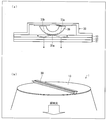
- FIG. 1 is a cross-sectional view illustrating a configuration of a main part of a lighting device in a ceiling light as a lighting device according to an embodiment of a lighting device including a lighting device according to the present invention.
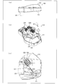
- (A) is a perspective view from the surface side which shows the structure of the said ceiling light
- (b) is a perspective view from the back surface side which shows the structure of the said ceiling light. It is a perspective view which shows the structure of the light source module in the said illuminating device.
- FIG. 1 is sectional drawing which shows an optical path when the light radiate
- (b) is the principal part which shows the optical path near a light emission part It is sectional drawing.
- (A) is sectional drawing which shows the optical path when the light radiate
- (b) is principal part cross section which shows the optical path near a light emission part.
- (A) is sectional drawing which shows the optical path when the light radiate
- (B) is a perspective view which shows the strip
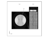
- (A) is a top view which shows the said light-guide plate,
- (b) is a graph which shows the luminance distribution on the string which passes along point A * B of (a).
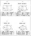
- (A) shows the structure of the modification of the said light-guide plate, Comprising: It is a top view which shows a rectangular light-guide plate, (b) is a top view which shows the light-guide plate which chamfered the rectangular corner
- FIG. 1 It is a perspective view which shows the structure of the modification of the light source module in the said illuminating device, Comprising: A frame-shaped light source module. It is sectional drawing which shows the toning illumination in the said illuminating device. It is a perspective view from the back side which shows the structure of the ceiling light which provided the radiation fin in the said illuminating device. It is a perspective view from the back side which shows the structure of the ceiling light in the case of adjusting input electric power in the center part and peripheral part of the said illuminating device. (A) is sectional drawing which shows the structure of the conventional lighting equipment, (b) is a top view which shows the structure of the lighting equipment, (c) is sectional drawing which shows the structure of the illuminating device in the lighting equipment.
- (D) is a plan view showing the configuration of the illumination device.
- (A) is a side view showing the configuration of another conventional lighting device,
- (b) is a perspective view showing the configuration of the other conventional lighting device, and
- (c) is another conventional lighting device. It is a perspective view which shows the principal part structure of this.
- FIGS. 1 to 13 An embodiment of the present invention will be described with reference to FIGS. 1 to 13 as follows.
- FIG. 1 is a cross-sectional view showing a configuration of a main part of a lighting device in a ceiling light.
- FIG. 2A is a perspective view showing the configuration of the ceiling light from the front side
- FIG. FIG. 3 is a perspective view from the back side showing the configuration of the ceiling light
- FIG. 3 is a perspective view from the front side showing the configuration of the light source module.
- the “front surface” direction is the direction of the light irradiation surface in the lighting device of the present invention
- the “back surface” direction is the opposite direction
- the “side surface” direction is The direction is orthogonal to both the front surface direction and the back surface direction. That is, when the lighting device of the present invention is installed as a ceiling light on the ceiling, the “front surface” is the room (floor) side, and the “back surface” is the ceiling side.
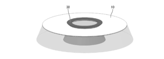
- the ceiling light 1 includes, for example, a disk-shaped lighting device 10, and the disk-shaped lighting device 10 includes a frame 20 on the outer periphery thereof.
- a light source module 30 is provided on the diameter of the disk as shown in FIG.
- the diameter of the ceiling light 1 is, for example, 550 mm, and the thinnest part is, for example, 10 mm.
- the shape and each dimension of the ceiling light 1 it is not restricted to this.
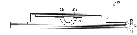
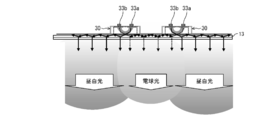
- the illuminating device 10 of the ceiling light 1 includes a diffusion sheet 11, an air layer 12, a light guide plate 13, and a light source module 30 provided in this order from the surface side as shown in FIG. 1.
- a portion of the back surface of the light guide plate 13 where the light source module 30 is not provided is provided with a reflection sheet 14 having an opening in that portion and a back chassis 15 as a metal chassis.
- the light source module 30 is provided with a sheet-shaped heat sink 32 on a light source holder 31 formed in a strip shape, and on the heat sink 32, a light emitting unit as a light source.
- LED boards 34a and 34b on which 33a and 33b (see FIG. 1) are mounted are provided.
- Spacers 36a and 36b are formed on the LED boards 34a and 34b to provide a gap between the LED boards 34a and 34b and the optical coupling member 35 described later. Due to this gap, it is possible to prevent the optical coupling member 35 from coming into contact with the light emitting portions 33a and 33b and damaging the light emitting portions 33a and 33b.
- the present invention is not limited to this, and the light emitting units 33a and 33b may be in close contact with the optical coupling member 35 as long as the light emitting units 33a and 33b are not damaged. Since the semiconductor light emitting part has a very fine size, the description of the light emitting part is omitted in FIG. 3 in order to prevent the drawing from being complicated. Moreover, in this Embodiment, although the light emission parts 33a * 33b are used as a light source, it is not necessarily this, For example, it is also possible to use an organic EL light emitting element or an inorganic EL light emitting element.
- the light emitting units 33a and 33b include a combination of a blue LED (Light Emitting Diode) chip and a yellow phosphor, a combination of a blue LED chip, a red phosphor and a green phosphor, It is composed of a combination of a blue LED chip, a red LED chip and a green LED chip, or an organic EL element.
- the light emitting sections 33a and 33b emit light having a color temperature of 2000K to 6000K. That is, red light in the morning sun or sunset has a color temperature of about 2000K, and sunlight has a color temperature of about 5000K to 6000K.
- a light emitting unit having a color temperature of 10,000 K to 20000 K is used as a light source used in a backlight of a liquid crystal display device.
- a plurality of the light emitting portions 33a and 33b are provided in parallel in two rows, and an optical coupling member 35 is provided above the light emitting portions 33a and 33b.
- the ceiling light 1 of the present embodiment includes a light guide plate 13 that irradiates light on the surface side, a light coupling member 35 as an optical element that couples light to the light guide plate 13, and the above
- the light coupling member 35 includes light emitting portions 33a and 33b that emit incident light, and the light guide plate 13, the light coupling member 35, and the light emitting portions 33a and 33b are arranged in this order from the front surface side to the back surface side of the lighting device 10. It consists of what is arranged. Therefore, the illuminating device 10 in the ceiling light 1 of the present embodiment is a illuminating device 10 directly under the light source in which the light emitting portions 33 a and 33 b are provided on the back side of the light guide plate 13.
- the optical coupling member 35 has a substantially semi-cylindrical cross section provided between the light guide plate 13 and the light emitting portions 33a and 33b. It consists of a strip-shaped body, that is, a rod-shaped body having a substantially U-shaped cross section.
- the material of the optical coupling member 35 is made of the same resin as that of the light guide plate 13. If the same material is used, the refractive index can be made the same, so that light is smoothly incident on the light guide plate 13 from the optical coupling member 35.
- the refractive index of the light guide plate 13 may be slightly higher than the refractive index of the optical coupling member 35.
- the material is not limited to resin, and a material such as glass may be used.
- the efficiency of coupling to the optical coupling member 35 can be improved by controlling the light distribution by forming a side wall (not shown) with a white resin or the like around the light emitting sections 33a and 33b.
- the optical coupling member 35 has a top flat surface 35a that abuts the flat light guide plate 13 on the surface of the optical coupling member 35 on the light guide plate 13 side.
- the top flat surface 35a has curved surfaces 35b and 35c on both ends.
- the curved surfaces 35b and 35c can be, for example, a cross-sectional parabola shown in FIG. However, it is not necessarily limited to this, and as shown in FIGS. 5 (a) and 5 (b), it may be an ellipse in cross section. In addition, a curved shape such as an arch shape, or oblique from the top flat surface 35a. Even if it is a plane inclined in a straight line, any shape that can effectively couple light to the light guide plate may be used.
- the surface of the optical coupling member 35 opposite to the light guide plate 13 side, that is, the lower end of the optical coupling member 35 is a lower flat surface 35d as shown in FIG.
- the spacers 36a and 36b described above are formed, and serve as spacers that prevent the light emitting portions 33a and 33b and the optical coupling member 35 from colliding with each other.
- the light emitting portions 33a and 33b are bonded to the LED substrates 34a and 34b, respectively.
- the spacers 36a and 36b are adhesively fixed to the LED boards 34a and 34b by applying an adhesive or the like.
- the light emitting portions 33a and 33b have a slight gap between them and the optical coupling member 35.
- the present invention is not limited to this, and the light emitting portions 33a and 33b are not limited thereto.
- the light emitting sections 33a and 33b may be in close contact with the optical coupling member 35 as long as the range does not damage 33b.
- a concave portion 35e is formed in the central portion on the lower end side of the optical coupling member 35.
- the configuration is not limited to this, and the concave portion 35e may not be present, and the optical coupling member 35 may have a substantially semicircular cross section. That is, in the present embodiment, it is only necessary to secure an optical path to the light guide plate 13 for the light reflected by the curved surfaces 35b and 35c. Therefore, a portion that does not become the optical path can be cut out as a recess 35e. Thereby, cost reduction and weight reduction can be achieved. It is also possible to provide a reflection means such as a reflection sheet (not shown) in the recess 35e. Thereby, even if stray light may be generated in the vicinity of the top flat surface 35a, a part of the stray light can be reflected to the light guide plate 13 side to improve irradiation on the surface side.
- Light emitting portions 33a and 33b are provided close to the optical coupling member 35 on the lower side (back side) of the lower flat surfaces 35d and 35d of the optical coupling member 35, respectively. As shown in FIGS. 4B and 5B, these light emitting portions 33a and 33b are arranged on the end side (side surface side) with respect to the focal position F of the curved surfaces 35b and 35c having a cross-section parabola or a cross-section ellipse. It is preferable that it exists in. Thereby, for example, as shown in FIG.
- light emitted from the light emitting portion 33 a is reflected by the curved surface 35 b of the parabolic parabola of the optical coupling member 35, and the reflected light is reflected by the optical coupling member 35. It reaches the top flat surface 35a, and enters the light guide plate 13 obliquely while maintaining the arrival direction. Then, the light incident on the light guide plate 13 is reflected by the inside of the right side of the light guide plate 13 shown in FIG. The angle of traveling through the light guide plate 13 is changed by colliding with a light scatterer, and the total reflection condition is broken, the light is emitted from the light guide plate 13, reflected by the reflection sheet 14, and further passed through the light guide plate 13.
- FIG. 6A schematically shows a state in which light from the left and right light emitting portions 33a and 33b passes through the optical coupling member 35, enters the light guide plate 13, and is totally reflected and propagated therein. It is.
- Such an optical path is the same in the optical coupling member 35 having an elliptical cross section shown in FIGS.
- the cross-sectional ellipse can be coupled so that the light is focused and incident on the light guide plate 13, so that the coupling efficiency can be increased.
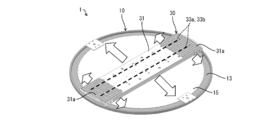
- the strip-shaped light source module 30 is crossed over the central portion of the disc-shaped ceiling light 1, that is, the center line.
- FIG. 7 (a) the chord passing through the points A and B, which are ⁇ 1/3 of the radius in the X-axis direction from the center of the light guide plate 13, as shown in FIG. Light emitted from the light guide plate 13 having the luminance distribution shown can be obtained.
- the ceiling light 1 of the present embodiment can obtain a uniform and smooth luminance distribution.
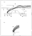
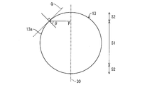
- the light P emitted from the light source module 30 provided on the center line reaches the outer peripheral end 13a.
- the light guide plate 13 of the present embodiment is made of, for example, an acrylic plate
- the radial direction (normal direction to the tangent line Q) at the outer peripheral end 13a is orthogonal to the light source module 30 according to Snell's law.
- the angle ⁇ formed by the direction is divided into a region S1 that is not totally reflected and regions S2 and S2 that are totally reflected with a boundary of about 42 degrees.
- the region S1 that is not totally reflected is a central side portion of the diameter, and the regions S2 and S2 that are totally reflected are both side portions of the diameter. For this reason, in the present embodiment, the brightness of the entire light guide plate 13 is further uniformed by adjusting the arrangement pattern of the light scattering portion which is an optical path conversion element (not shown).
- the illuminating device 10 of this Embodiment As shown in FIG. 1, the light of light emission part 33a * 33b is entered from the back surface side of the light-guide plate 13. As shown in FIG.
- a side edge type backlight has been conventionally used.
- the light utilization efficiency of the conventional side edge type backlight is 75%.
- the light use efficiency of the lighting apparatus 10 of the present embodiment was 88%.
- the illuminating device 10 of this Embodiment is excellent in light utilization efficiency rather than the conventional side edge type
- the linear expansion accompanying the temperature rise in the longitudinal direction of the light guide plate is large, it is necessary to provide a gap between the LED chip and the light guide plate. As a result, the LED chip Since the emitted light from the light leaks from this gap, the light utilization efficiency could not be increased.
- the light emitting portions 33a and 33b are provided immediately below the light guide plate 13, the expansion dimension is small even when the light guide plate 13 is thermally expanded. Therefore, since it is not necessary to provide a gap, the light utilization efficiency can be increased.
- the illumination device 10 of the present embodiment unlike the conventional side-edge type backlight, there is no light source at the end of the ceiling light 1 as shown in FIG. It is possible to provide the frame 20 directly at the end of the frame. As a result, surface light emission with a frame size of 6 mm or less is possible. Further, by forming the frame 20 from a transparent, translucent or milky white resin material, it is possible to emit light from the entire surface including the frame 20. By optimizing the shape and material of the frame 20, indirect illumination that emits light in the back surface direction is possible.
- the illumination device 10 has a disk shape, for example.
- the present invention is not limited to this, and various shapes may be used as shown in FIGS. 9 (a) to 9 (d). it can.
- FIG. 9A shows a rectangular light guide plate 13
- FIG. 9B shows a light guide plate 13 with rectangular corners chamfered
- FIG. 9C shows an elliptical guide
- FIG. 9D shows a light guide plate 13 which is a diamond-shaped light guide plate 13.
- the amount of light in the light guide direction of the light from the light source module 30, that is, the direction orthogonal to the light source module 30 extending in a strip shape (traveling direction) is Decrease gradually.
- the distribution of the dot pattern of the light scattering portion can obtain a uniform luminance distribution from the light guide plate 13 to the surface side by increasing the number of dot patterns as it goes in the traveling direction.
- the amount of light is constant, and as a result, the distribution of the dot pattern of the light scattering portion is also uniform.
- the rectangular portion is the same as FIG. 9A. That is, the amount of light gradually decreases in the light guide direction (traveling direction) of light from the light source module 30. For this reason, the distribution of the dot pattern of the light scattering portion can obtain a uniform luminance distribution from the light guide plate 13 to the surface side by increasing the number of dot patterns as it goes in the traveling direction. In the direction perpendicular to the light guide direction (vertical direction), the amount of light is constant, and as a result, the dot pattern distribution in the light scattering portion is also uniform.
- the light quantity gradually decreases in the light guide direction (traveling direction) of the light from the light source module 30.
- the distribution of the dot pattern of the light scattering portion can obtain a uniform luminance distribution from the light guide plate 13 to the surface side by increasing the number of dot patterns as it goes in the traveling direction.
- the light is totally reflected.
- the light proceeds in the vertical direction. Accordingly, it is necessary to reduce the dot pattern of the light scattering portion.
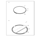
- the light source module 30 of the illuminating device 10 is provided in strip
- it can be a ring shape that is a frame shape.
- the frame-shaped light source module 30 that follows the shape of the illumination device 10, it is possible to easily achieve uniform luminance.
- the light source module 30 is provided with two rows of light emitting portions 33a and 33b along the longitudinal direction of the optical coupling member 35. Therefore, by adjusting the color temperatures of the light emitting sections 33a and 33b in the two rows, as shown in FIG. 11, dimming and toning illumination can be performed.
- the light emitting unit 33a is daylight white and the light emitting unit 33b is a light bulb color. Thereby, it is possible to perform dimming and toning illumination such as irradiating daylight white light outside the ceiling light 1 and illuminating a light bulb color inside the ceiling light 1.
- the light source modules 30 are provided in one row, but the present invention is not necessarily limited to this, and a plurality of rows may be provided. Thereby, improvement in brightness and dimming illumination are possible.
- the light emitting sections 33 a and 33 b are arranged so that the optical axis direction of the emitted light toward the optical coupling member 35 is orthogonal to the light guide plate 13. For this reason, since it is not necessary to arrange the light emitting portions 33a and 33b obliquely with respect to the flat light guide plate 13, the light emitting portions 33a and 33b can be easily arranged and the structure is simple.
- the light emitting units 33a and 33b emit light having a color temperature of 2000K to 6000K. For this reason, it can be appropriately used as an illumination device such as the ceiling light 1.
- the illuminating device 10 that can uniformly irradiate the entire light guide plate 13 without increasing the number of the light emitting portions 33a and 33b and processing the light guide plate.
- the light guide plate 13 is not processed and light is incident from below, so that the light guide plate 13 and the ceiling light 1 can be thinned. Specifically, a certain amount of thickness is required for processing the light guide plate 13. In this case, for example, when an edge light type light guide plate is considered, if the light guide plate 13 is made thinner than the widths of the light emitting portions 33a and 33b, the optical coupling rate is lowered, so that there is a limit to thinning. In this regard, in the present embodiment, if the light guide plate 13 is thinned, the ceiling light 1 is thinned. Moreover, since the material of the light guide plate 13 can be saved, the cost can be reduced.
- the light emitting portions 33a and 33b may be mounted so that the optical axis thereof is perpendicular to the light guide plate 13, the assembly is simple. That is, in the case of the conventional edge light, since it is necessary to attach the light emitting parts 33a and 33b from the side surfaces, the manufacture becomes somewhat difficult.
- the optical coupling member 35 is provided in a band shape.
- the optical coupling member 35 may be a double row. In this case, in particular, it is preferable to arrange them symmetrically with respect to the vertical or horizontal center line of the light guide plate 13 so that the luminance distribution of the double-row optical coupling members 35 is symmetrical. Further, when the optical coupling members 35 are in a double row, the luminance of light emitted from the surface of the light guide plate 13 is such that the luminance at the center of the flat light guide plate 13 is higher than the luminance at the end of the light guide plate 13. It is desirable to arrange in.
- the optical coupling member 35 is provided on the center line in the vertical or horizontal direction of the flat light guide plate 13. This makes it possible to make the luminance symmetric about the vertical or horizontal center line of the light guide plate 13 as an axis. Therefore, it is possible to provide the lighting device 10 suitable for the luminance distribution.
- the light source includes a plurality of light emitting units 33a and 33b.
- the light emitting units 33a and 33b have lower power consumption and lower heat generation than incandescent bulbs, and can save energy.
- the ceiling light 1 as the lighting fixture of the present embodiment includes a lighting device 10.
- the ceiling light 1 provided with the illuminating device 10 which enables uniform irradiation in the whole light-guide plate 13 without the increase in the number of light emission parts 33a * 33b and the process of the light-guide plate 13 can be provided. .
- a back chassis 15 that is a flat chassis that holds the light guide plate 13 in a flat surface is provided below the light guide plate 13, and the back chassis 15 is guided.
- the optical plate holding surface has an opening at a portion where the optical coupling member 35 contacts the light guide plate 13, and the optical coupling member 35 and the light emitting portions 33 a and 33 b are positioned below the light guide plate holding surface of the back chassis 15. Yes.
- the optical coupling member 35 and the light emitting portions 33a and 33b protrude on the back surface side of the light guide plate 13. Accordingly, it is possible to reduce the thickness of portions other than the optical coupling member 35 and the light emitting portions 33a and 33b. For this reason, the overall thickness can be reduced. Further, by adopting such a configuration, the heat radiation of the light emitting portions 33a and 33b is excellent. Moreover, since the back chassis 15 functions as a heat sink by connecting the light source module 30 to the back chassis 15, high heat dissipation performance can be obtained. As a result, the light emission efficiency of the light emitting units 33a and 33b is also improved.
- the light emitting portions 33 a and 33 b are arranged in two rows along the longitudinal direction of the optical coupling member 35. Specifically, the light emitting units 33a and 33b are provided in two rows in parallel along the center line directly below both ends of the lower end chord in the optical coupling member 35 having a semicircular cross section.
- the light emitting portions 33a and 33b of the two rows emit light in opposite directions, so that the line passing through the midpoint between the two rows is axially symmetric and both sides of the optical coupling member 35 That is, the light can be guided to both ends of the light guide plate 13.
- the line passing through the midpoint between the two rows coincides with the center line of the light guide plate 13
- the light guide plate is guided to both ends of the light guide plate with the center line of the light guide plate 13 being axially symmetrical.
- a luminance distribution that is axially symmetric about the 13 center lines can be obtained. Therefore, the luminance distribution can be made uniform in the light guide plate 13 with a simple structure. That is, when the light emitting part 33a is used alone, there is a possibility that the light above the light emitting part 33a does not transmit light and becomes a dark part. This can be supplemented with light from the other light emitting section 33b.
- the diffusion sheet 11 is not stuck with respect to the light-guide plate 13, and an air layer is provided between the diffusion sheet 11 and the light-guide plate 13.
- FIG. 12 is provided.
- the illumination device 10 of the present embodiment can be applied to a large planar light source as it is, and can provide a large ceiling light 1. Furthermore, since no member is required around the light guide plate 13, it can be applied to a larger ceiling light 1 by arranging them seamlessly.
- the illuminating device 10 of this Embodiment is from the integrated thing which supports the some light emission part 33a * 33b and the some light emission part 33a * 33b, and radiates the heat
- the illumination device 10 has a disk shape, and a plurality of light emitting portions 33a and 33b are arranged on the center line of the disk.
- the distance from the light source module 30 provided on the center line in the direction orthogonal to the disk-shaped center line to the outer peripheral end 13a that is an arc is the central portion on the disk-shaped center line.
- the distance from the non-total reflection region S1 to the arc is longer than the distance from the total reflection regions S2 and S2, which are the end portions on the center line of the disk shape, to the arc.
- the metal chassis has a larger radiation area in the light emitting portions 33a and 33b arranged in the central portion on the disc-shaped center line than the plurality of light emitting portions 33a and 33b arranged on the disc-shaped center line. In the light emitting portions 33a and 33b arranged at the end portions on the center line of the disk shape, the radiation area is small. Therefore, the back chassis 15 is different in heat radiation area from the light emitting portions 33a and 33b.
- a heat uniform radiation means for ensuring the uniformity of heat radiation in the entire region of the back chassis 15 is provided.
- the back chassis 15 is formed as a single unit with respect to the plurality of light emitting units 33a and 33b arranged side by side, so that the back chassis 15 is not provided for each of the light emitting units 33a and 33b. .
- the lighting device 10 that can uniformly dissipate the plurality of light emitting portions 33a and 33b and thereby suppress a decrease in lifetime without increasing the number of parts and complicating the manufacturing process. .
- the heat uniform radiation means includes heat radiation fins 31a and 31a provided in a small area of the heat radiation area for the plurality of light emitting portions 33a and 33b in the back chassis 15. can do. That is, heat radiation fins (fin) 31 a and 31 a are provided at both ends of the light source holder 31 of the light source module 30 integrated with the back chassis 15.
- the heat radiating fins 31a and 31a are formed, for example, by a plurality of ribs standing on a metal flat plate such as aluminum (Al).
- the heat of the light emitting portions 33a and 33b can be efficiently radiated by the heat radiating fins 31a and 31a as the uniform heat radiation means.
- the radiating fins 31 a and 31 a are provided in a region where the heat radiation region for the light emitting portions 33 a and 33 b in the back chassis 15 is small. For this reason, uniform heat dissipation of the plurality of light emitting units 33a and 33b can be performed.
- the heat radiating fins 31a are disposed only in the peripheral portion of the ceiling light 1, but may be disposed in a region toward the center in addition to the peripheral portion. With this arrangement, the heat dissipation performance can be further improved.
- a heat radiation sheet made of a silicone material or a graphite material may be interposed between the back chassis 15 and the heat radiation fins 31a.
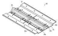
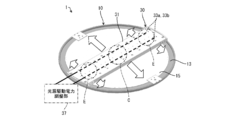
- the uniform heat radiation means includes the light emitting sections 33a according to the size of the heat radiation area for the plurality of light emitting sections 33a and 33b in the back chassis 15, as shown in FIG. It can be assumed that the light source drive power adjustment unit 37 is used as light source power adjustment means for reducing the output power to 33b. The light source driving power adjustment unit 37 is actually mounted inside the light source holder 31.
- heat dissipation from the light emitting portions 33 a and 33 b of the peripheral portions E and E to the back chassis 15 in the disk-shaped lighting device 10 which is both ends in the longitudinal direction of the light source holder 31 is a heat radiation region. Therefore, the driving power of the light emitting portions 33a and 33b existing in the peripheral portions E and E is small.
- the heat dissipation from the light emitting portions 33a and 33b in the central portion C in the longitudinal direction of the light source holder 31 to the back chassis 15 is a region having a large heat radiation region, and thus the light emitting portions 33a and.
- the drive power of 33b is large.
- the light source driving power adjusting unit 37 as the uniform heat radiation means changes the output power to the light emitting units 33a and 33b according to the size of the heat radiation area for the plurality of light emitting units 33a and 33b in the back chassis 15. It can be adjusted to be large or small. Therefore, it is possible to provide the lighting device 10 that can uniformly dissipate the plurality of light emitting units 33a and 33b and thereby suppress the reduction of the lifetime.
- the lighting device 10 of the present embodiment includes a flat light guide plate 13 and a plurality of light emitting units 33a and 33b arranged on the back side of the light guide plate 13, and the light emitting units 33a and 33b
- the emitted light is incident on the light guide plate 13, and the incident light is totally reflected inside the light guide plate 13 and guided from the surface side of the light guide plate 13 while being guided.
- An optical coupling member 35 that couples light emitted from the light emitting portions 33a and 33b so that light is incident obliquely on the light guide plate 13 is provided between the light guide plate 13 and the light emitting portions 33a and 33b. It has been.
- the back chassis 15 is integrally provided on the back surface of the light guide plate 13 and the back surfaces of the light emitting portions 33a and 33b.
- the illuminating device 10 that can uniformly irradiate the entire light guide plate 13 without increasing the number of the light emitting portions 33a and 33b and processing the light guide plate.
- the lighting device 10 of the present embodiment includes the lighting device 10 described above. Therefore, the ceiling light provided with the lighting device 10 that can uniformly dissipate the light emitting portions 33a and 33b and suppress the decrease in the lifetime without increasing the number of parts and complicating the manufacturing process. 1 can be provided.
- heat from the light source can be efficiently radiated by applying an alumite treatment or heat radiation paint using heat radiation on the surface of the back chassis 15 or the heat radiation fin 31a of the present embodiment.
- the uniform heat radiation means can be composed of heat radiation fins provided in a small heat radiation area for the plurality of light sources in the metal chassis. is there.
- the heat of the light source can be efficiently radiated by the radiating fin as the uniform heat radiation means.
- the radiation fin is provided in the area
- the heat uniform radiation means includes light source power adjustment means that increases or decreases the output power to each light source according to the size of the heat radiation area for the plurality of light sources in the metal chassis. can do.
- the light source power adjusting means as the heat uniform radiation means can adjust the output power to each light source according to the size of the heat radiation area for the plurality of light sources in the metal chassis.
- the illuminating device of the present invention includes a flat light guide plate and the plurality of light sources arranged on the back side of the light guide plate.
- the light emitted from the light source is incident on the light guide plate.
- Optical coupling that couples the light emitted from the light source so that light is incident on the light guide plate obliquely while being irradiated from the surface side of the light guide plate while being totally reflected inside the light guide plate and guiding the light.
- a member may be provided between the light guide plate and the light source, and the metal chassis may be provided integrally on the back surface of the light guide plate and the back surface of the light source.
- an optical coupling member that couples light emitted from the light source so that light is incident on the light guide plate obliquely.
- the light emitted from the light source on the back surface of the light guide plate is coupled to the light guide plate through the optical coupling member and is incident obliquely, and moves to the end of the light guide plate while totally reflecting the inside of the light guide plate.
- the total reflection condition is broken by the optical path conversion element, and the light is emitted to the surface side of the light guide plate.
- the present invention by providing an optical coupling member separate from the light guide plate, light is incident obliquely on the flat light guide plate and totally reflected inside the light guide plate to be guided to the whole. be able to. As a result, even if the light guide plate is not processed, incident light from the light source can be guided inside the light guide plate via the optical coupling member, and light can be irradiated uniformly from the light guide plate.
- the lighting device of the present invention and the lighting device including the lighting device can be applied to ceiling-mounted ceiling lights, wall lighting attached to a wall surface, signboards, and the like. And as an application field, it can apply to various lighting fixtures, such as facilities, such as a store and an office, and business.
Landscapes
- Engineering & Computer Science (AREA)
- General Engineering & Computer Science (AREA)
- Physics & Mathematics (AREA)
- General Physics & Mathematics (AREA)
- Optics & Photonics (AREA)
- Planar Illumination Modules (AREA)
- Arrangement Of Elements, Cooling, Sealing, Or The Like Of Lighting Devices (AREA)
Abstract
本発明の照明装置(10)は、複数の発光部(33a・33b)と、複数の発光部(33a・33b)を支持し、かつ該複数の発光部(33a・33b)からの熱を放射する一体物からなるバックシャーシ(15)とを有している。複数の発光部(33a・33b)は、バックシャーシ(15)に一体化された光源ホルダー(31)に並んで配されている。バックシャーシ(15)は、発光部(33a・33b)に対して熱の放射領域が異なっている。バックシャーシ(15)の全領域における熱放射の均一性を確保する熱均一放射手段としての例えば放熱フィン(31a・31a)が設けられている。
Description
本発明は、光源からの光を導光板によって面状に出射させる照明装置、及びそれを備えた照明機器に関するものである。
従来、照明装置においては、白熱球に替わって低消費電力・低発熱性による省エネルギー化が可能なLED(Light Emitting Diode:発光ダイオード)が用いられている。すなわち、LED照明は、供給される電力の多くが発光に使われ、つまり発光効率が高いために、従来の白熱照明と同じ明るさを作るのに必要な電力が少なくて済む。また、消費電力が少ないということは、従来では熱となって失われていた電力分の発熱が少なくて済み、低発熱な照明器具となるという特徴を有している。
そして、近年では、白熱球に代替するLED電球のみならず、天井面に固定されるシーリングライト等に対してもLEDを用いた照明器具が出現するようになってきている。
例えば、特許文献1には、LEDを用いて器具本体の側方及び背面方向に光を放射させて、天井面を明るくすることが可能な照明器具が開示されている。
上記特許文献1に開示された照明器具100は、住宅用の天井直付け形のシーリングライトであり、図14の(a)(b)に示すように、器具本体110と、該器具本体110の前面及び側面を覆う透光カバー101と、該透光カバー101の周縁部101aから器具本体110の側方及び背面方向に向けて光を放射させる光制御体102とを備えている。
そして、器具本体110には、複数のLEDを有する発光モジュール120と、LEDを点灯する点灯装置111とが備えられている。上記発光モジュール120は、図14の(c)(d)に示すように、基体121と、この基体121の上に搭載された複数のLEDチップ122a…とこれらLEDチップ122a…により励起される黄色蛍光体122bとで構成されて高輝度、高出力の白色の光を発光する半導体発光素子122とを備えている。
この構成により、器具本体110の側方及び背面方向に光を放射させ、天井面を明るくすることが可能な照明器具100を提供するものとなっている。
ところで、上記従来の特許文献1に開示された照明器具100では、光源としてLEDを用いているので、LEDからの放熱を適切に行わなければ、LEDの発光効率及び寿命が低下するという問題点を有している。
そこで、この問題に対応するために、例えば特許文献2に開示されたLED照明器具では、放熱フィンを用いてLEDの熱を放熱している。具体的には、特許文献2に開示されたLED照明器具としての道路灯200は、シーリングライトではないが、図15の(a)(b)(c)に示すように、照射開口211が設けられた器具本体210が支柱201に取り付けられたものからなっている。上記器具本体210は、複数のLED221を上記照射開口211に臨む位置に配置した光源ユニット220を備えている。そして、この光源ユニット220は、LED221を取り付けたLED担持板222の裏面側に放熱部材である熱伝導板223と放熱フィン224とを備えている。
しかしながら、特許文献2に開示されたLED照明器具としての道路灯200の熱伝導板223及び放熱フィン224は、光源ユニット220毎に設けられており、部品点数の増加を招き、製造工程の煩雑化を招くという問題を有している。
また、複数の光源を有する場合に、各光源の寿命が均一でなければ、照明器具としては寿命が低下することに繋がる。
本発明は、上記従来の問題点に鑑みなされたものであって、その目的は、部品点数の増加及び製造工程の煩雑化を招くことなく、複数の光源の均一な放熱を行い、延いては寿命の低下を抑制し得る照明装置、及びそれを備えた照明機器を提供することにある。
本発明の照明装置は、上記課題を解決するために、複数の光源と、上記複数の光源を支持し、かつ該複数の光源からの熱を放射する一体物からなる金属シャーシとを有する照明装置であって、上記複数の光源は、金属シャーシに並んで配されており、上記金属シャーシは、上記光源に対して熱の放射領域が異なっていると共に、上記金属シャーシの全領域における熱放射の均一性を確保する熱均一放射手段が設けられていることを特徴としている。
上記の発明によれば、照明装置は、複数の光源と、複数の光源を支持し、かつ該複数の光源からの熱を放射する一体物からなる金属シャーシとを有している。そして、複数の光源は、金属シャーシに並んで配されており、金属シャーシは、光源に対して熱の放射領域が異なっている。このような形態として、例えば、照明装置が円盤形状であり、複数の光源が円盤の中心線上に並んでいる場合が相当する。この場合、円盤形状の中心線に直交する方向における中心線から円弧までの距離は、円盤形状の中心線上の中央部分から円弧までの距離の方が、円盤形状の中心線上の端部から円弧までの距離よりも長い。この結果、金属シャーシは、円盤形状の中心線上に配された複数の光源に対して、円盤形状の中心線上の中央部分に配された光源では放射領域が大きく、円盤形状の中心線上の端部に配された光源では放射領域が小さくなっている。したがって、金属シャーシは、光源に対して熱の放射領域が異なっていることになる。
このような照明装置においては、各光源の不均一な寿命の低下を抑制するために、複数の光源からの熱を金属シャーシにて均一に放熱する必要がある。そこで、本発明では、金属シャーシの全領域における熱放射の均一性を確保する熱均一放射手段が設けられている。
これにより、熱均一放射手段にて、金属シャーシの全領域における熱放射の均一性が確保される。
また、この構成では、並んで配された複数の光源に対して金属シャーシは一体物からなっているので、光源毎に金属シャーシが設けられるということはない。
したがって、部品点数の増加及び製造工程の煩雑化を招くことなく、複数の光源の均一な放熱を行い、延いては寿命の低下を抑制し得る照明装置を提供することができる。
本発明の照明機器は、上記課題を解決するために、前記照明装置を備えていることを特徴としている。
上記の発明によれば、部品点数の増加及び製造工程の煩雑化を招くことなく、複数の光源の均一な放熱を行い、延いては寿命の低下を抑制し得る照明装置を備えた照明機器を提供することができる。
本発明の照明装置は、以上のように、複数の光源は、金属シャーシに並んで配されており、上記金属シャーシは、上記光源に対して熱の放射領域が異なっていると共に、上記金属シャーシの全領域における熱放射の均一性を確保する熱均一放射手段が設けられているものである。
また、本発明の照明機器は、以上のように、前記照明装置を備えているものである。
それゆえ、部品点数の増加及び製造工程の煩雑化を招くことなく、複数の光源の均一な放熱を行い、延いては寿命の低下を抑制し得る照明装置、及びそれを備えた照明機器を提供するという効果を奏する。
本発明の一実施形態について図1~図13に基づいて説明すれば、以下のとおりである。
本実施の形態の照明装置を備えた照明機器としてのシーリングライトの構成について、図1、図2の(a)(b)及び図3に基づいて説明する。図1はシーリングライトにおける照明装置の要部の構成を示す断面図であり、図2の(a)はシーリングライトの構成を示す、表面側からの斜視図であり、図2の(b)はシーリングライトの構成を示す、裏面側からの斜視図であり、図3は光源モジュールの構成を示す、表面側からの斜視図である。尚、本明細書中において、特に説明がない限り、「表面」方向は、本発明の照明装置における光照射面の向きであり、「裏面」方向はその逆向きであり、「側面」方向は、表面方向および裏面方向の両方に直交する向きである。すなわち、本発明の照明装置がシーリングライトとして天井に設置された場合、「表面」は室内(床)側であり、「裏面」は天井側である。
上記シーリングライト1は、図2の(a)に示すように、例えば円盤状の照明装置10を備えており、この円盤状の照明装置10は、その外周にフレーム20を備えている。また、シーリングライト1の裏面では、図2の(b)に示すように、円盤の直径上に光源モジュール30が設けられている。このシーリングライト1の直径は例えば550mmであり、最薄部は例えば10mmとなっている。尚、シーリングライト1の形状及び各寸法についてはこれに限らない。
上記シーリングライト1の照明装置10は、図1に示すように、表面側から順に設けられた、拡散シート11、空気層12、導光板13及び光源モジュール30にて構成されている。導光板13の裏面における光源モジュール30が設けられていない部分には、その部分が開口となった反射シート14及び金属シャーシとしてのバックシャーシ15が設けられている。
上記光源モジュール30には、図3に示すように、帯状に形成された光源ホルダー31の上にシート状のヒートシンク32が設けられていると共に、このヒートシンク32の上には、光源としての発光部33a・33b(図1参照)を搭載したLED基板34a・34bが設けられている。LED基板34a・34b上には、LED基板34a・34bと後述する光結合部材35との間に隙間を設けるためのスペーサ36a・36bが形成されている。この隙間により、光結合部材35が発光部33a・33bに当接して、発光部33a・33bが破損することを防止できる。但し、これに限られず、発光部33a・33bに損傷を与えない範囲であれば、発光部33a・33bが光結合部材35と密着していても構わない。尚、半導体の発光部は非常に微細なサイズであるため、図3では、図面の煩雑さを防ぐため発光部の記載を割愛する。また、本実施の形態では、光源として発光部33a・33bを用いているが、必ずしもこれに限らず、例えば、有機EL発光素子又は無機EL発光素子を用いることも可能である。
ここで、本実施の形態では、発光部33a・33bは、青色LED(Light Emitting Diode:発光ダイオード)チップと黄色蛍光体との組み合わせ、青色LEDチップと赤色蛍光体と緑色蛍光体との組み合わせ、青色LEDチップと赤色LEDチップと緑色LEDチップとの組み合わせ、又は有機EL素子等にて構成される。そして、発光部33a・33bは、色温度2000K~6000Kの光を出射するものとなっている。すなわち、朝日や夕日の赤色光は、色温度約2000Kであり、太陽光線は色温度約5000K~6000Kである。尚、液晶表示装置のバックライトで使用される光源では、例えば、色温度10000K~20000Kの発光部が用いられる。
上記発光部33a・33bは、2列に並んで互いに平行に複数個設けられていると共に、それら複数の発光部33a・33bの上側には、光結合部材35が設けられている。
すなわち、本実施の形態のシーリングライト1は、図1に示すように、表面側に光を照射する導光板13と、導光板13に光を結合する光学素子としての光結合部材35と、上記光結合部材35に入射光を発する発光部33a・33bとを備え、照明装置10の表面側から裏面側へ向けて、導光板13、光結合部材35、発光部33a・33bがこの順に並んで配設されたものからなっている。したがって、本実施の形態のシーリングライト1における照明装置10は、発光部33a・33bが導光板13の裏面側に設けられた光源直下型の照明装置10となっている。
ここで、本実施の形態では、光結合部材35は、図4の(a)(b)に示すように、導光板13と発光部33a・33bとの間に設けられた断面略かまぼこ状の帯状体つまり断面略U字形状の棒状体からなっている。光結合部材35の材質は導光板13の材質と同じ樹脂からなっている。同じ材質であれば、屈折率を同じにすることができるので、光結合部材35から導光板13への光の入射が円滑に行われる。導光板13の屈折率が光結合部材35の屈折率よりも僅かに高い構成でも構わない。また、樹脂に限るものではなく硝子等の材質でも構わない。さらに、発光部33a・33bの周囲に白色樹脂等にて図示しない側壁を形成して配光制御をすることによって、光結合部材35への結合効率を向上することができる。
上記光結合部材35は、詳細には、図4の(a)に示すように、光結合部材35における導光板13側の表面は、平板状の導光板13に当接する頂部平坦面35aと、この頂部平坦面35aから両端側にそれぞれ曲面35b・35cを有する形状からなっている。
上記曲面35b・35cは、例えば、図4の(a)に示す断面放物線とすることができる。ただし、必ずしもこれに限るものではなく、図5の(a)(b)に示すように、断面楕円とすることも可能であり、その他、弓型等の湾曲形状、又は頂部平坦面35aから斜めに傾斜する平面であっても、導光板に光を有効に結合できる形状であれば構わない。
上記光結合部材35における導光板13側とは反対側の面、つまり光結合部材35の下端は、図4の(a)に示すように、下端平坦面35dとなっており、その一部に上述したスペーサ36a・36bが形成され、発光部33a・33bと光結合部材35の衝突を防ぐスペーサになっている。発光部33a・33bは、LED基板34a・34bにそれぞれボンディングされている。上記スペーサ36a・36bは、接着剤等を塗布し、LED基板34a・34bと接着固定されている。尚、図4の(a)(b)に示すように、発光部33a・33bは、光結合部材35との間に若干の隙間が形成されているが、これに限られず、発光部33a・33bに損傷を与えない範囲であれば、発光部33a・33bが光結合部材35と密着していても構わない。
また、光結合部材35の下端側の中央部には凹部35eが形成されている。ただし、必ずしもこれに限らず、凹部35eが存在せず、光結合部材35の断面が略半円状の詰った構成でも構わない。すなわち、本実施の形態では、曲面35b・35cにて反射する光の導光板13への光路が確保できればよいので、光路とならない部分は凹部35eとしてくり抜くことができる。これにより、コスト削減及び軽量化を図ることができる。尚、凹部35eに図示しない反射シート等の反射手段を設けることも可能である。これにより、頂部平坦面35a近傍で迷光が発生する場合があっても迷光の一部を導光板13側に反射させその表面側への照射を向上させることができる。
上記光結合部材35の下端平坦面35d・35dの下側(裏面側)には、発光部33a・33bがそれぞれ光結合部材35に近接して設けられている。これら発光部33a・33bは、図4の(b)及び図5の(b)に示すように、断面放物線又は断面楕円からなる曲面35b・35cの焦点位置Fよりも端部側(側面側)に存在することが好ましい。これにより、例えば、図4の(a)に示すように、例えば発光部33aから出射された光が光結合部材35の断面放物線の曲面35bにて反射され、その反射光が光結合部材35の頂部平坦面35aに到達し、到達方向を維持して導光板13に斜めに入射する。そして、導光板13に入射された光は、図4の(a)に示す導光板13の右側の内部を全反射して進みつつ、導光板13の下面又は上面に形成された図示しない光路変換部である光散乱体と衝突することにより導光板13中を進む角度が変わり、全反射条件が破られ、導光板13から出射し、反射シート14にて反射し、さらに導光板13内を通過し、導光板13の表面から出射し、上記拡散シート11を通して前記シーリングライト1から発光される。尚、発光部33bから出射された光も、図6の(a)に示すように、発光部33aからの光とは対称に進む。すなわち、左右の発光部33a・33bからの光が光結合部材35を通過し、導光板13に入射し、その内部を全反射伝搬する様子を模式的に示したものが図6の(a)である。
このような光路は、図5の(a)(b)に示す断面楕円の光結合部材35においても同様である。
このように、光結合部材35における曲面35b・35cの形状を断面放物線又は断面楕円とすることによって、発光部33a・33bからの出射光を、断面放物線又は断面楕円の曲面35b・35cにて反射させて効率よく結合して頂部平坦面35aから導光板13に入射させることができ、図6の(a)に示すように、シーリングライト1から照明光を出射することができる。尚、断面放物線と断面楕円との対比においては、断面楕円の方が光を絞って導光板13に入射するよう結合できるので、結合効率を高くすることができる。
この結果、本実施の形態のシーリングライト1における照明装置10では、図6の(b)に示すように、円盤状のシーリングライト1における中央部、つまり中心線上に横切って帯状の光源モジュール30を設けることにより、図7の(a)に示すように、導光板13の中心からX軸方向に半径の±約1/3離れた点A・Bを通る弦において、図7の(b)に示す輝度分布を有する導光板13からの出射光を得ることができる。この結果、本実施の形態のシーリングライト1では均一で滑らかな輝度分布を得ることが可能となる。
ここで、本実施の形態における円盤状のシーリングライト1の輝度分布について説明する。
すなわち、本実施の形態では、図8に示すように、円盤状の導光板13において、中心線上に設けられた光源モジュール30から出射された光Pは外周端13aに達する。ここで、本実施の形態の導光板13は例えばアクリル板にてなっているので、スネルの法則により、外周端13aでの半径方向(接線Qとの法線方向)と光源モジュール30と直交する方向とのなす角度θが約42度を境界として、全反射しない領域S1と全反射する領域S2・S2とに分かれる。全反射しない領域S1は直径の中央側部であり、全反射する領域S2・S2は直径の両端側部である。このため、本実施の形態では、図示しない光路変換素子である光散乱部の配設パターン等を調整することにより、導光板13全体の輝度のさらなる均一化を図っている。
また、本実施の形態の照明装置10では、図1に示すように、導光板13の裏面側から発光部33a・33bの光を入射させる。ここで、液晶表示装置のバックライトの分野においては、従来、サイドエッジ型のバックライトが用いられていたが、従来のサイドエッジ型のバックライトの光利用効率が75%であるのに対して、本実施の形態の照明装置10の光利用効率は88%であった。このように、本実施の形態の照明装置10は、従来のサイドエッジ型のバックライトよりも光利用効率において優れていることが判る。すなわち、従来のサイドエッジ型のバックライトでは、導光板の長手方向の温度上昇に伴う線膨張が大きいことから、LEDチップと導光板との間に隙間を設ける必要があり、その結果、LEDチップの出射光がこの隙間から漏れるので、光利用効率を上げることができなかった。この点、本実施の形態の照明装置10では、導光板13の直下に発光部33a・33bを設けているので、導光板13が熱膨張したときにも膨張寸法は小さい。したがって、隙間を設ける必要がないので、光利用効率を上げることができるものとなっている。
また、その結果、本実施の形態の照明装置10では、従来のサイドエッジ型のバックライトとは異なり、図1に示すように、シーリングライト1の端部に光源が存在しないので、シーリングライト1の端部に、直接、フレーム20を設けることが可能である。この結果、額縁寸法を6mm以下にした面発光が可能になる。さらに、フレーム20を透明、半透明又は乳白色の樹脂材料にて構成することによって、フレーム20も含めた全面発光が可能になる。フレーム20の形状や材質を最適化することにより、裏面方向に発光する間接照明が可能になる。
ところで、本実施の形態では、照明装置10は、例えば円盤状となっているが、必ずしもこれに限らず、図9の(a)~(d)に示すように、各種の形状とすることができる。具体的には、図9の(a)は矩形の導光板13であり、図9の(b)は矩形の角が面取りされた導光板13であり、図9の(c)は楕円の導光板13であり、図9の(d)は菱形の導光板13である。
この場合、図9の(a)に示す矩形の導光板13では、光源モジュール30からの光の導光方向、つまり帯状に延伸する光源モジュール30に直交する方向(進行方向)においては、光量は徐々に減少する。このため、光散乱部のドットパターンの分布は進行方向に向かうに伴ってドットパターンの数を増加させることにより、導光板13から表面側への均一な輝度分布を得ることができる。一方、光の導光方向に垂直な方向(垂直方向)においては、光量は一定であり、この結果、光散乱部のドットパターンの分布も均一である。
また、図9の(b)に示す矩形の角が面取りされた導光板13では、方形部分では、図9の(a)と同様である。すなわち、光源モジュール30からの光の導光方向(進行方向)においては、光量は徐々に減少する。このため、光散乱部のドットパターンの分布は進行方向に向かうに伴ってドットパターンの数を増加させることにより、導光板13から表面側への均一な輝度分布を得ることができる。また、光の導光方向に垂直な方向(垂直方向)においては、光量は一定であり、この結果、光散乱部のドットパターンの分布も均一である。
一方、矩形の角の面取り部分では、光の導光方向に垂直な方向(垂直方向)において、光は全反射し、この結果、導光板13から表面側への均一な輝度分布を得るためには、垂直方向に進むに伴って、光散乱部のドットパターンを減少させる必要がある。
さらに、図9の(c)に示す楕円の導光板13では、光源モジュール30からの光の導光方向(進行方向)においては、光量は徐々に減少する。このため、光散乱部のドットパターンの分布は進行方向に向かうに伴ってドットパターンの数を増加させることにより、導光板13から表面側への均一な輝度分布を得ることができる。一方、光の導光方向に垂直な方向(垂直方向)においては、光は全反射し、この結果、導光板13から表面側への均一な輝度分布を得るためには、垂直方向に進むに伴って、光散乱部のドットパターンを減少させる必要がある。
また、図9の(d)に示す菱形の導光板13では、光源モジュール30からの光の導光方向(進行方向)においては、光量は徐々に減少する。このため、光散乱部のドットパターンの分布は進行方向に向かうに伴ってドットパターンの数を増加させることにより、導光板13から表面側への均一な輝度分布を得ることができる。一方、光の導光方向に垂直な方向(垂直方向)においては、光は全反射し、この結果、導光板13から表面側への均一な輝度分布を得るためには、垂直方向に進むに伴って、光散乱部のドットパターンを減少させる必要がある。
尚、本実施の形態では、照明装置10の光源モジュール30は、帯状に設けられているが、必ずしもこれに限ることはない。例えば、図10に示すように、枠状であるリング状とすることが可能である。このように、照明装置10の形状に沿う枠状の光源モジュール30とすることによって、輝度の均一化を容易に図ることができる。
また、本実施の形態の光源モジュール30では、上述したように、光源モジュール30においては光結合部材35の長手方向に沿って2列の発光部33a・33bが設けられている。したがって、この2列の発光部33a・33bの色温度をそれぞれ異ならせることによって、図11に示すように、調光・調色照明が可能となる。具体的には、発光部33aを昼白色とし、発光部33bを電球色とする。これにより、前記シーリングライト1の外側では昼白光を照射し、シーリングライト1の内側では電球色を照射する等の調光・調色照明を行うことが可能となる。
さらに、本実施の形態では、光源モジュール30は1列にて設けられていたが、必ずしもこれに限らず、複数列であってもよい。これにより、明るさの向上及び調光照明が可能となる。
このように、本実施の形態の照明装置10では、導光板13と発光部33a・33bとの間には、導光板13に対して斜めに光を入射させるように発光部33a・33bからの出射光を結合する光結合部材35が設けられている。このため、導光板13の裏面の発光部33a・33bから出射された光は光結合部材35を介して導光板13に結合して斜めに入射され、導光板13の内部を全反射しながら導光板13の端部まで移動し、その途中で光路変換素子である光散乱部にて全反射条件が破れて導光板13の表面側に出射される。
この結果、発光部33a・33bを光結合部材35の裏面に沿って並べるだけで、導光板13の全面から光を照射することができる。この結果、発光部33a・33bを導光板13の裏面の全体に配置するのに比べて、発光部33a・33bの個数を減らすことができる。
また、本実施の形態では、導光板13とは別体の光結合部材35を設けることにより、平板状の導光板13に対して斜めに光を入射させ、導光板13の内部で全反射させて全体に導光させることができる。この結果、導光板13を加工しなくても、光結合部材35を介して、発光部33a・33bからの入射光を導光板13の内部にて導光させ、導光板13から均一に光を照射することができる。
さらに、本実施の形態では、発光部33a・33bは、光結合部材35へ向けての出射光の光軸方向が導光板13に対して直交するように配置されている。このため、発光部33a・33bの配置を平板状の導光板13に対して斜めにする必要がないので、発光部33a・33bの配置も容易であり、構造が単純である。
また、本実施の形態では、発光部33a・33bは色温度2000K~6000Kの光を出射する。このため、シーリングライト1等の照明機器として適切に利用することができる。
したがって、発光部33a・33bの個数の増加及び導光板の加工を伴うことなく、導光板13の全体での均一照射を可能とする照明装置10を提供することができる。
また、本実施の形態では、導光板13を加工せずに済み、かつ下方から光入射するので、導光板13及びシーリングライト1の薄型化を図ることができる。具体的には、導光板13の加工にはある程度の厚さが必要である。この場合、例えば、エッジライト方式の導光板を考えた場合、発光部33a・33bの幅よりも導光板13を薄くすると光結合率が低下するため薄型化に限界がある。この点、本実施の形態では、導光板13を薄型化すれば、シーリングライト1の薄型化に繋がる。また、導光板13の材料を節約できるので、低コスト化を図ることができる。また、発光部33a・33bをその光軸が導光板13に垂直になるように実装すればよいので、組み立てが簡単である。すなわち、従来のエッジライトの場合は、側面から発光部33a・33bを取り付ける必要があるので、製造がやや困難となる。
また、本実施の形態の照明装置10では、光結合部材35は、帯状に設けられている。
これにより、光結合部材35と発光部33a・33bとの関係を1:1にする必要がなくなり、複数の発光部33a・33bを1つの光学部材にて覆うので、光学系の構造を単純化することができる。また、発光部33a・33bも光結合部材35に沿って設けることができるので、発光部33a・33bの配線が容易となる。
尚、光結合部材35が帯状に設けられている構成においては、光結合部材35が複列であってもよい。この場合、特に、複列の光結合部材35の輝度分布が対称になるように、導光板13の縦又は横の中心線に対称に配置することが好ましい。また、光結合部材35が複列の場合は、導光板13の表面から出射される光の輝度は、平板状の導光板13における中央の輝度が導光板13の端の輝度よりも高くなるように配置することが望ましい。
また、本実施の形態の照明装置10では、光結合部材35は、平板状の導光板13における縦又は横方向の中心線上に設けられている。これにより、導光板13における縦又は横方向の中心線を軸として輝度を対称にすることが可能となる。したがって、輝度分布において適切な照明装置10を提供することが可能となる。
また、本実施の形態の照明装置10では、光源は、複数の発光部33a・33bからなっている。これにより、発光部33a・33bは、白熱球に比べて低消費電力・低発熱性であり、省エネルギー化が可能となる。
さらに、本実施の形態の照明器具としてのシーリングライト1は、照明装置10を備えている。これにより、発光部33a・33bの個数の増加及び導光板13の加工を伴うことなく、導光板13全体での均一照射を可能とする照明装置10を備えたシーリングライト1を提供することができる。
また、本実施の形態の照明装置10では、導光板13の下側には、導光板13を平面で保持する平板状のシャーシであるバックシャーシ15が設けられていると共に、バックシャーシ15の導光板保持面は、光結合部材35が導光板13に当接する部分に開口を有し、光結合部材35及び発光部33a・33bは、バックシャーシ15の導光板保持面よりも下方に位置している。
このような構成とすることによって、導光板13の裏面側においては、光結合部材35及び発光部33a・33bのみが突出していることになる。したがって、光結合部材35及び発光部33a・33b以外の部分を薄型化することが可能となる。このため、全体として薄型化を図ることができる。さらに、このような構成とすることによって、発光部33a・33bの放熱の面でも優れたものとなる。また、光源モジュール30をバックシャーシ15と接続しておくことによって、バックシャーシ15が放熱板として機能するので、高い放熱性能を得ることができる。この結果、発光部33a・33bの発光効率も向上する。
また、本実施の形態のシーリングライト1では、発光部33a・33bは、光結合部材35の長手方向に沿って2列になっている。具体的には、発光部33a・33bは、断面半円状の光結合部材35における下端弦の両端部の直下に中心線に沿って平行に2列に設けられている。
これにより、導光板13に入射させるときに、2列の発光部33a・33bをそれぞれ反対方向に光出射させることによって、2列間の中点を通る線を軸対称として光結合部材35の両側つまり導光板13の両端側にそれぞれ導光させることができる。尚、上記2列間の中点を通る線が導光板13の中心線に一致する場合には、導光板13の中心線を軸対称として導光板の両端側にそれぞれ導光させて該導光板13の中心線に軸対称となる輝度分布を得ることができる。したがって、単純な構造にて、導光板13において輝度分布の均一化を図ることができる。すなわち、発光部33aが単独の場合は、発光部33aの直上が光透過せずに暗部となる虞がある。それを他の発光部33bからの光にて補うことが可能となる。
また、本実施の形態の照明装置10では、図1に示すように、拡散シート11は導光板13に対して貼着されておらず、拡散シート11と導光板13との間には空気層12が設けられている。これにより、導光板13には光散乱部のドットパターンが形成されているが、空気層12の存在によりこれらドットパターンが表面側から視認されるのを防止することができる。
また、本実施の形態の照明装置10は、そのまま大型平面光源への適用が可能であり、大きなシーリングライト1を提供することも可能である。さらに、導光板13の周辺に部材が不要であることから、シームレスに並べることにより、さらに、大きなシーリングライト1への適用が可能である。
ところで、本実施の形態の照明装置10は、複数の発光部33a・33bと、複数の発光部33a・33bを支持し、かつ該複数の発光部33a・33bからの熱を放射する一体物からなるバックシャーシ15とを有している。すなわち、発光部33a・33bは、金属からなる光源ホルダー31に支持されており、この光源ホルダー31は、バックシャーシ15と一体化されている。そして、複数の発光部33a・33bは、光源ホルダー31に並んで配されており、バックシャーシ15は、発光部33a・33bに対して熱の放射領域が異なっている。詳細には、照明装置10が円盤形状であり、複数の発光部33a・33bが円盤の中心線上に並んでいる。
この場合、前記図8に示すように、円盤形状の中心線に直交する方向における中心線に設けられた光源モジュール30から円弧である外周端13aまでの距離は、円盤形状の中心線上の中央部分である全反射しない領域S1から円弧までの距離の方が、円盤形状の中心線上の端部である全反射する領域S2・S2から円弧までの距離よりも長い。この結果、金属シャーシは、円盤形状の中心線上に配された複数の発光部33a・33bに対して、円盤形状の中心線上の中央部分に配された発光部33a・33bでは放射領域が大きく、円盤形状の中心線上の端部に配された発光部33a・33bでは放射領域が小さくなっている。したがって、バックシャーシ15は、発光部33a・33bに対して熱の放射領域が異なっていることになる。
このような照明装置10においては、各発光部33a・33bの不均一な寿命の低下を抑制するために、複数の発光部33a・33bからの熱をバックシャーシ15にて均一に放熱する必要がある。そこで、本実施の形態では、バックシャーシ15の全領域における熱放射の均一性を確保する熱均一放射手段が設けられている。
これにより、熱均一放射手段にて、バックシャーシ15の全領域における熱放射の均一性が確保される。
また、この構成では、並んで配された複数の発光部33a・33bに対してバックシャーシ15は一体物からなっているので、発光部33a・33b毎にバックシャーシ15が設けられるということはない。
したがって、部品点数の増加及び製造工程の煩雑化を招くことなく、複数の発光部33a・33bの均一な放熱を行い、延いては寿命の低下を抑制し得る照明装置10を提供することができる。
ここで、上記熱均一放射手段は、図12に示すように、バックシャーシ15における複数の発光部33a・33bに対する熱の放射領域の小さい領域に設けられた放熱フィン31a・31aからなっているとすることができる。すなわち、バックシャーシ15と一体化された光源モジュール30の光源ホルダー31の両端部には、放熱フィン(fin)31a・31aが設けられている。この放熱フィン31a・31aは、例えば、アルミニウム(Al)等の金属平板に複数のリブが立設されたものからなっている。
これにより、熱均一放射手段としての放熱フィン31a・31aにて、発光部33a・33bの熱を効率的に放熱することができる。そして、本実施の形態では、放熱フィン31a・31aは、バックシャーシ15における複数の発光部33a・33bに対する熱の放射領域の小さい領域に設けられている。このため、複数の発光部33a・33bの均一な放熱を行うことができる。
ここで、図12に示すように、放熱フィン31aは、シーリングライト1の周辺部のみに配置しているが、周辺部に加えて中心に向かう領域に配置してもよい。この配置により、さらに放熱性能を向上させることが可能となる。
また、放熱フィン31aとバックシャーシ15とのそれぞれの面精度が出ていない場合、発光部33a・33bからバックシャーシ15及び放熱フィン31aの熱伝達経路での熱抵抗が大きくなる。そこで、熱抵抗を小さくするために、バックシャーシ15と放熱フィン31aとの間にシリコーン系材料やグラファイト系材料からなる放熱シートを介してもよい。これにより、熱抵抗を低減することができ、光源からの熱を効率良く放射することができる。
また、本実施の形態の照明装置10では、熱均一放射手段は、図13に示すように、バックシャーシ15における複数の発光部33a・33bに対する熱の放射領域の大小に応じて各発光部33a・33bへの出力電力を大小とする光源電力調整手段として光源駆動電力調整部37からなっているとすることができる。尚、この光源駆動電力調整部37は、実際には、光源ホルダー31の内部に搭載されている。
すなわち、図13においては、光源ホルダー31の長手方向の両端部である円盤状の照明装置10における周辺部E・Eの発光部33a・33bからバックシャーシ15への熱放散は、熱の放射領域の小さい領域であるので、この周辺部E・Eに存在する発光部33a・33bの駆動電力は小さいものとなっている。一方、光源ホルダー31の長手方向における中央部Cの発光部33a・33bからバックシャーシ15への熱放散は、熱の放射領域の大きい領域であるので、この中央部Cに存在する発光部33a・33bの駆動電力は大きいものとなっている。
これにより、熱均一放射手段としての光源駆動電力調整部37にて、バックシャーシ15における複数の発光部33a・33bに対する熱の放射領域の大小に応じて各発光部33a・33bへの出力電力を大小とするように調整することができる。したがって、複数の発光部33a・33bの均一な放熱を行い、延いては寿命の低下を抑制し得る照明装置10を提供することができる。
また、本実施の形態の照明装置10では、平板状の導光板13と、該導光板13の裏面側に配置された複数の発光部33a・33bとを備え、該発光部33a・33bからの出射光を該導光板13に入射させ、入射した光を該導光板13の内部で全反射させて導光しながら該導光板13の表面側から照射させる。そして、導光板13に対して斜めに光を入射させるように発光部33a・33bからの出射光を結合する光結合部材35が、該導光板13と該発光部33a・33bとの間に設けられている。また、バックシャーシ15は、導光板13の裏面及び発光部33a・33bの裏面に一体に設けられている。
したがって、発光部33a・33bの個数の増加及び導光板の加工を伴うことなく、導光板13全体での均一照射を可能とする照明装置10を提供することができる。
本実施の形態の照明装置10は、上記照明装置10を備えている。それゆえ、部品点数の増加及び製造工程の煩雑化を招くことなく、複数の発光部33a・33bの均一な放熱を行い、延いては寿命の低下を抑制し得る照明装置10を備えたシーリングライト1を提供することができる。
また、本実施の形態のバックシャーシ15又は放熱フィン31aの表面に、アルマイト処理や熱の放射を利用する放熱塗料を塗布することにより、光源からの熱を効率良く、放射することができる。
以上のように、本発明の照明装置では、前記熱均一放射手段は、前記金属シャーシにおける複数の光源に対する熱の放射領域の小さい領域に設けられた放熱フィンからなっているとすることが可能である。
これにより、熱均一放射手段としての放熱フィンにて、光源の熱を効率的に放熱することができる。そして、本発明では、放熱フィンは、金属シャーシにおける複数の光源に対する熱の放射領域の小さい領域に設けられている。
このため、複数の光源の均一な放熱を行うことができる。
本発明の照明装置では、前記熱均一放射手段は、前記金属シャーシにおける複数の光源に対する熱の放射領域の大小に応じて各光源への出力電力を大小とする光源電力調整手段からなっているとすることができる。
これにより、熱均一放射手段としての光源電力調整手段にて、金属シャーシにおける複数の光源に対する熱の放射領域の大小に応じて各光源への出力電力を大小とするように調整することができる。
したがって、複数の光源の均一な放熱を行い、延いては寿命の低下を抑制し得る照明装置を提供することができる。
本発明の照明装置では、平板状の導光板と、該導光板の裏面側に配置された前記複数の光源とを備え、該光源からの出射光を該導光板に入射させ、入射した光を該導光板の内部で全反射させて導光しながら該導光板の表面側から照射させると共に、上記導光板に対して斜めに光を入射させるように上記光源からの出射光を結合する光結合部材が、該導光板と該光源との間に設けられており、前記金属シャーシは、上記導光板の裏面及び光源の裏面に一体に設けられているとすることができる。
これにより、導光板と光源との間には、導光板に対して斜めに光を入射させるように光源からの出射光を結合する光結合部材が設けられている。このため、導光板の裏面の光源から出射された光は光結合部材を介して導光板に結合して斜めに入射され、導光板の内部を全反射しながら導光板の端部まで移動し、その途中で光路変換素子にて全反射条件が破れて導光板の表面側に出射される。
この結果、光源を光結合部材の裏面に沿って並べるだけで、導光板の全面から光を照射することができる。この結果、光源を導光板の裏面の全体に配置するのに比べて、光源の個数を減らすことができる。
また、本発明では、導光板とは別体の光結合部材を設けることにより、平板状の導光板に対して斜めに光を入射させ、導光板の内部で全反射させて全体に導光させることができる。この結果、導光板を加工しなくても、光結合部材を介して、光源からの入射光を導光板の内部にて導光させ、導光板から均一に光を照射することができる。
したがって、光源の個数の増加及び導光板の加工を伴うことなく、導光板全体での均一照射を可能とする照明装置を提供することができる。
尚、本発明は、上述した実施形態に限定されるものではなく、請求項に示した範囲で種々の変更が可能であり、本実施形態にそれぞれ開示された技術的手段を適宜組み合わせて得られる実施形態についても本発明の技術的範囲に含まれる。
本発明の照明装置、及びそれを備えた照明機器は、天井直付け形のシーリングライト、壁面に取り付ける壁面照明や、看板等に適用できる。そして、適用分野として、店舗、オフィス等施設、業務用などの各種の照明器具に適用できる。
1 シーリングライト(照明機器)
10 照明装置
11 拡散シート
12 空気層
13 導光板
14 反射シート
15 バックシャーシ(金属シャーシ)
20 フレーム
30 光源モジュール
31 光源ホルダー(金属シャーシ)
31a 放熱フィン(熱均一放射手段)
33a・33b 発光部(光源)
35 光結合部材
35a 頂部平坦面
35b・35c 曲面
35d 下端平坦面
37 光源駆動電力調整部(熱均一放射手段、光源電力調整手段)
C 中央部
E 周辺部
10 照明装置
11 拡散シート
12 空気層
13 導光板
14 反射シート
15 バックシャーシ(金属シャーシ)
20 フレーム
30 光源モジュール
31 光源ホルダー(金属シャーシ)
31a 放熱フィン(熱均一放射手段)
33a・33b 発光部(光源)
35 光結合部材
35a 頂部平坦面
35b・35c 曲面
35d 下端平坦面
37 光源駆動電力調整部(熱均一放射手段、光源電力調整手段)
C 中央部
E 周辺部
Claims (5)
- 複数の光源と、上記複数の光源を支持し、かつ該複数の光源からの熱を放射する一体物からなる金属シャーシとを有する照明装置であって、
上記複数の光源は、金属シャーシに並んで配されており、
上記金属シャーシは、上記光源に対して熱の放射領域が異なっていると共に、
上記金属シャーシの全領域における熱放射の均一性を確保する熱均一放射手段が設けられていることを特徴とする照明装置。 - 前記熱均一放射手段は、
前記金属シャーシにおける複数の光源に対する熱の放射領域の小さい領域に設けられた放熱フィンからなっていることを特徴とする請求項1記載の照明装置。 - 前記熱均一放射手段は、
前記金属シャーシにおける複数の光源に対する熱の放射領域の大小に応じて各光源への出力電力を大小とする光源電力調整手段からなっていることを特徴とする請求項1記載の照明装置。 - 平板状の導光板と、該導光板の裏面側に配置された前記複数の光源とを備え、該光源からの出射光を該導光板に入射させ、入射した光を該導光板の内部で全反射させて導光しながら該導光板の表面側から照射させると共に、
上記導光板に対して斜めに光を入射させるように上記光源からの出射光を結合する光結合部材が、該導光板と該光源との間に設けられており、
前記金属シャーシは、上記導光板の裏面及び光源の裏面に一体に設けられていることを特徴とする請求項1記載の照明装置。 - 請求項1記載の照明装置を備えていることを特徴とする照明機器。
Applications Claiming Priority (2)
| Application Number | Priority Date | Filing Date | Title |
|---|---|---|---|
| JP2011093409A JP2012226967A (ja) | 2011-04-19 | 2011-04-19 | 照明装置、及びそれを備えた照明機器 |
| JP2011-093409 | 2011-04-19 |
Publications (1)
| Publication Number | Publication Date |
|---|---|
| WO2012144394A1 true WO2012144394A1 (ja) | 2012-10-26 |
Family
ID=47041505
Family Applications (1)
| Application Number | Title | Priority Date | Filing Date |
|---|---|---|---|
| PCT/JP2012/059939 Ceased WO2012144394A1 (ja) | 2011-04-19 | 2012-04-11 | 照明装置、及びそれを備えた照明機器 |
Country Status (2)
| Country | Link |
|---|---|
| JP (1) | JP2012226967A (ja) |
| WO (1) | WO2012144394A1 (ja) |
Cited By (1)
| Publication number | Priority date | Publication date | Assignee | Title |
|---|---|---|---|---|
| FR2995971A1 (fr) * | 2012-09-26 | 2014-03-28 | Valeo Vision | Dispositif d'eclairage, notamment pour vehicule automobile. |
Citations (4)
| Publication number | Priority date | Publication date | Assignee | Title |
|---|---|---|---|---|
| JP2000030521A (ja) * | 1998-07-08 | 2000-01-28 | Mitsubishi Electric Corp | 面発光光源 |
| JP2009075565A (ja) * | 2007-07-29 | 2009-04-09 | Cree Inc | Lcdディスプレイ用のledバックライト・システム |
| JP2010049994A (ja) * | 2008-08-22 | 2010-03-04 | Panasonic Corp | バックライト装置及び液晶表示装置 |
| WO2011040089A1 (ja) * | 2009-10-02 | 2011-04-07 | シャープ株式会社 | 照明装置、及び表示装置 |
-
2011
- 2011-04-19 JP JP2011093409A patent/JP2012226967A/ja active Pending
-
2012
- 2012-04-11 WO PCT/JP2012/059939 patent/WO2012144394A1/ja not_active Ceased
Patent Citations (4)
| Publication number | Priority date | Publication date | Assignee | Title |
|---|---|---|---|---|
| JP2000030521A (ja) * | 1998-07-08 | 2000-01-28 | Mitsubishi Electric Corp | 面発光光源 |
| JP2009075565A (ja) * | 2007-07-29 | 2009-04-09 | Cree Inc | Lcdディスプレイ用のledバックライト・システム |
| JP2010049994A (ja) * | 2008-08-22 | 2010-03-04 | Panasonic Corp | バックライト装置及び液晶表示装置 |
| WO2011040089A1 (ja) * | 2009-10-02 | 2011-04-07 | シャープ株式会社 | 照明装置、及び表示装置 |
Cited By (2)
| Publication number | Priority date | Publication date | Assignee | Title |
|---|---|---|---|---|
| FR2995971A1 (fr) * | 2012-09-26 | 2014-03-28 | Valeo Vision | Dispositif d'eclairage, notamment pour vehicule automobile. |
| WO2014048847A1 (fr) * | 2012-09-26 | 2014-04-03 | Valeo Vision | Dispositif d'éclairage, notamment pour véhicule automobile |
Also Published As
| Publication number | Publication date |
|---|---|
| JP2012226967A (ja) | 2012-11-15 |
Similar Documents
| Publication | Publication Date | Title |
|---|---|---|
| US8297797B2 (en) | Lighting apparatus | |
| CN103339436B (zh) | Led照明装置 | |
| CN101975345B (zh) | Led日光灯 | |
| TWI509187B (zh) | 照明器具 | |
| CN101922633A (zh) | Led照明装置 | |
| JP2013500560A (ja) | ランプ | |
| CN102348928A (zh) | 发光模块及照明器具 | |
| KR20100115864A (ko) | 눈부심 방지 기능을 가진 엘이디 조명 램프 | |
| WO2013145049A1 (ja) | ランプ | |
| JP5133439B2 (ja) | 照明装置、及びそれを備えた照明機器 | |
| WO2012144393A1 (ja) | 照明装置、及びそれを備えた照明機器 | |
| WO2012144394A1 (ja) | 照明装置、及びそれを備えた照明機器 | |
| JP2012226966A (ja) | 照明装置、及びそれを備えた照明機器 | |
| JP2012226965A (ja) | 照明装置、及びそれを備えた照明機器 | |
| KR101220909B1 (ko) | 형광등형 엘이디 조명등 | |
| TWI409412B (zh) | Led照明裝置 | |
| WO2016107513A1 (zh) | 发光二极管灯泡结构 | |
| TWI442004B (zh) | 光源模組 | |
| CN101725901A (zh) | 光源模组 | |
| JP2012204218A (ja) | 照明装置、及びそれを備えた照明機器 | |
| TWI402454B (zh) | Led日光燈 | |
| TWI393842B (zh) | Led照明裝置 | |
| JPWO2017002960A1 (ja) | 照明装置 | |
| JP2012204217A (ja) | 照明装置、及びそれを備えた照明機器 | |
| TWI516719B (zh) | 燈具 |
Legal Events
| Date | Code | Title | Description |
|---|---|---|---|
| 121 | Ep: the epo has been informed by wipo that ep was designated in this application |
Ref document number: 12773664 Country of ref document: EP Kind code of ref document: A1 |
|
| NENP | Non-entry into the national phase |
Ref country code: DE |
|
| 122 | Ep: pct application non-entry in european phase |
Ref document number: 12773664 Country of ref document: EP Kind code of ref document: A1 |