WO2012144394A1 - Unité d'éclairage et dispositif d'éclairage associé - Google Patents
Unité d'éclairage et dispositif d'éclairage associé Download PDFInfo
- Publication number
- WO2012144394A1 WO2012144394A1 PCT/JP2012/059939 JP2012059939W WO2012144394A1 WO 2012144394 A1 WO2012144394 A1 WO 2012144394A1 JP 2012059939 W JP2012059939 W JP 2012059939W WO 2012144394 A1 WO2012144394 A1 WO 2012144394A1
- Authority
- WO
- WIPO (PCT)
- Prior art keywords
- light
- guide plate
- light guide
- light emitting
- light source
- Prior art date
- Legal status (The legal status is an assumption and is not a legal conclusion. Google has not performed a legal analysis and makes no representation as to the accuracy of the status listed.)
- Ceased
Links
Images


Classifications
-
- F—MECHANICAL ENGINEERING; LIGHTING; HEATING; WEAPONS; BLASTING
- F21—LIGHTING
- F21S—NON-PORTABLE LIGHTING DEVICES; SYSTEMS THEREOF; VEHICLE LIGHTING DEVICES SPECIALLY ADAPTED FOR VEHICLE EXTERIORS
- F21S8/00—Lighting devices intended for fixed installation
- F21S8/04—Lighting devices intended for fixed installation intended only for mounting on a ceiling or the like overhead structures
-
- F—MECHANICAL ENGINEERING; LIGHTING; HEATING; WEAPONS; BLASTING
- F21—LIGHTING
- F21V—FUNCTIONAL FEATURES OR DETAILS OF LIGHTING DEVICES OR SYSTEMS THEREOF; STRUCTURAL COMBINATIONS OF LIGHTING DEVICES WITH OTHER ARTICLES, NOT OTHERWISE PROVIDED FOR
- F21V29/00—Protecting lighting devices from thermal damage; Cooling or heating arrangements specially adapted for lighting devices or systems
- F21V29/50—Cooling arrangements
- F21V29/70—Cooling arrangements characterised by passive heat-dissipating elements, e.g. heat-sinks
-
- G—PHYSICS
- G02—OPTICS
- G02B—OPTICAL ELEMENTS, SYSTEMS OR APPARATUS
- G02B6/00—Light guides; Structural details of arrangements comprising light guides and other optical elements, e.g. couplings
- G02B6/0001—Light guides; Structural details of arrangements comprising light guides and other optical elements, e.g. couplings specially adapted for lighting devices or systems
- G02B6/0011—Light guides; Structural details of arrangements comprising light guides and other optical elements, e.g. couplings specially adapted for lighting devices or systems the light guides being planar or of plate-like form
- G02B6/0081—Mechanical or electrical aspects of the light guide and light source in the lighting device peculiar to the adaptation to planar light guides, e.g. concerning packaging
- G02B6/0085—Means for removing heat created by the light source from the package
-
- F—MECHANICAL ENGINEERING; LIGHTING; HEATING; WEAPONS; BLASTING
- F21—LIGHTING
- F21V—FUNCTIONAL FEATURES OR DETAILS OF LIGHTING DEVICES OR SYSTEMS THEREOF; STRUCTURAL COMBINATIONS OF LIGHTING DEVICES WITH OTHER ARTICLES, NOT OTHERWISE PROVIDED FOR
- F21V7/00—Reflectors for light sources
- F21V7/0008—Reflectors for light sources providing for indirect lighting
- F21V7/0016—Reflectors for light sources providing for indirect lighting on lighting devices that also provide for direct lighting, e.g. by means of independent light sources, by splitting of the light beam, by switching between both lighting modes
-
- F—MECHANICAL ENGINEERING; LIGHTING; HEATING; WEAPONS; BLASTING
- F21—LIGHTING
- F21W—INDEXING SCHEME ASSOCIATED WITH SUBCLASSES F21K, F21L, F21S and F21V, RELATING TO USES OR APPLICATIONS OF LIGHTING DEVICES OR SYSTEMS
- F21W2131/00—Use or application of lighting devices or systems not provided for in codes F21W2102/00-F21W2121/00
- F21W2131/10—Outdoor lighting
- F21W2131/103—Outdoor lighting of streets or roads
-
- F—MECHANICAL ENGINEERING; LIGHTING; HEATING; WEAPONS; BLASTING
- F21—LIGHTING
- F21Y—INDEXING SCHEME ASSOCIATED WITH SUBCLASSES F21K, F21L, F21S and F21V, RELATING TO THE FORM OR THE KIND OF THE LIGHT SOURCES OR OF THE COLOUR OF THE LIGHT EMITTED
- F21Y2105/00—Planar light sources
-
- F—MECHANICAL ENGINEERING; LIGHTING; HEATING; WEAPONS; BLASTING
- F21—LIGHTING
- F21Y—INDEXING SCHEME ASSOCIATED WITH SUBCLASSES F21K, F21L, F21S and F21V, RELATING TO THE FORM OR THE KIND OF THE LIGHT SOURCES OR OF THE COLOUR OF THE LIGHT EMITTED
- F21Y2115/00—Light-generating elements of semiconductor light sources
- F21Y2115/10—Light-emitting diodes [LED]
-
- F—MECHANICAL ENGINEERING; LIGHTING; HEATING; WEAPONS; BLASTING
- F21—LIGHTING
- F21Y—INDEXING SCHEME ASSOCIATED WITH SUBCLASSES F21K, F21L, F21S and F21V, RELATING TO THE FORM OR THE KIND OF THE LIGHT SOURCES OR OF THE COLOUR OF THE LIGHT EMITTED
- F21Y2115/00—Light-generating elements of semiconductor light sources
- F21Y2115/20—Electroluminescent [EL] light sources
-
- G—PHYSICS
- G02—OPTICS
- G02B—OPTICAL ELEMENTS, SYSTEMS OR APPARATUS
- G02B6/00—Light guides; Structural details of arrangements comprising light guides and other optical elements, e.g. couplings
- G02B6/0001—Light guides; Structural details of arrangements comprising light guides and other optical elements, e.g. couplings specially adapted for lighting devices or systems
- G02B6/0011—Light guides; Structural details of arrangements comprising light guides and other optical elements, e.g. couplings specially adapted for lighting devices or systems the light guides being planar or of plate-like form
- G02B6/0013—Means for improving the coupling-in of light from the light source into the light guide
- G02B6/0023—Means for improving the coupling-in of light from the light source into the light guide provided by one optical element, or plurality thereof, placed between the light guide and the light source, or around the light source
- G02B6/0028—Light guide, e.g. taper
-
- G—PHYSICS
- G02—OPTICS
- G02B—OPTICAL ELEMENTS, SYSTEMS OR APPARATUS
- G02B6/00—Light guides; Structural details of arrangements comprising light guides and other optical elements, e.g. couplings
- G02B6/0001—Light guides; Structural details of arrangements comprising light guides and other optical elements, e.g. couplings specially adapted for lighting devices or systems
- G02B6/0011—Light guides; Structural details of arrangements comprising light guides and other optical elements, e.g. couplings specially adapted for lighting devices or systems the light guides being planar or of plate-like form
- G02B6/0013—Means for improving the coupling-in of light from the light source into the light guide
- G02B6/0023—Means for improving the coupling-in of light from the light source into the light guide provided by one optical element, or plurality thereof, placed between the light guide and the light source, or around the light source
- G02B6/0031—Reflecting element, sheet or layer
-
- G—PHYSICS
- G02—OPTICS
- G02B—OPTICAL ELEMENTS, SYSTEMS OR APPARATUS
- G02B6/00—Light guides; Structural details of arrangements comprising light guides and other optical elements, e.g. couplings
- G02B6/0001—Light guides; Structural details of arrangements comprising light guides and other optical elements, e.g. couplings specially adapted for lighting devices or systems
- G02B6/0011—Light guides; Structural details of arrangements comprising light guides and other optical elements, e.g. couplings specially adapted for lighting devices or systems the light guides being planar or of plate-like form
- G02B6/0033—Means for improving the coupling-out of light from the light guide
- G02B6/005—Means for improving the coupling-out of light from the light guide provided by one optical element, or plurality thereof, placed on the light output side of the light guide
- G02B6/0055—Reflecting element, sheet or layer
Definitions
- the present invention relates to an illumination device that emits light from a light source in a planar shape by a light guide plate, and an illumination device including the illumination device.
- an LED Light ⁇ ⁇ Emitting ⁇ ⁇ Diode: light emitting diode
- the LED lighting requires less power to produce the same brightness as the conventional incandescent lighting.
- the low power consumption is characterized by the fact that less heat is generated for the power that has been lost as heat in the prior art, and the lighting apparatus has a low heat generation.
- Patent Literature 1 discloses a lighting fixture that can illuminate a ceiling surface by emitting light toward the side and back of the fixture body using LEDs.
- the lighting fixture 100 disclosed in Patent Document 1 is a ceiling-mounted ceiling light for home use. As shown in FIGS. 14A and 14B, the fixture main body 110 and the fixture main body 110 are provided. A translucent cover 101 that covers the front and side surfaces, and a light control body 102 that emits light from the peripheral edge portion 101a of the translucent cover 101 toward the side and back of the instrument main body 110 are provided.
- the appliance main body 110 includes a light emitting module 120 having a plurality of LEDs and a lighting device 111 that lights the LEDs. As shown in FIGS. 14C and 14D, the light emitting module 120 is yellow excited by a base 121, a plurality of LED chips 122a mounted on the base 121, and the LED chips 122a. And a semiconductor light emitting element 122 configured to emit white light with high luminance and high output.
- the heat of the LED is radiated using the radiation fins.
- the road lamp 200 as an LED lighting apparatus disclosed in Patent Document 2 is not a ceiling light, but an irradiation opening 211 is provided as shown in FIGS. 15 (a), 15 (b), and 15 (c).
- the instrument body 210 is attached to the column 201.
- the instrument main body 210 includes a light source unit 220 in which a plurality of LEDs 221 are arranged at a position facing the irradiation opening 211.
- the light source unit 220 includes a heat conductive plate 223 and heat radiating fins 224 as heat radiating members on the back side of the LED carrying plate 222 to which the LEDs 221 are attached.
- the heat conductive plate 223 and the heat radiating fins 224 of the road lamp 200 as the LED lighting apparatus disclosed in Patent Document 2 are provided for each light source unit 220, leading to an increase in the number of parts and a complicated manufacturing process. Have the problem of inviting.
- the present invention has been made in view of the above-described conventional problems, and its purpose is to uniformly dissipate a plurality of light sources without increasing the number of components and complicating the manufacturing process. It is providing the illuminating device which can suppress the fall of a lifetime, and an illuminating device provided with the same.
- an illumination device includes a plurality of light sources and a metal chassis that supports the plurality of light sources and that is an integrated body that radiates heat from the plurality of light sources.
- the plurality of light sources are arranged side by side in a metal chassis, and the metal chassis has a heat radiation area different from that of the light source, and heat radiation in all areas of the metal chassis.
- a heat uniform radiation means for ensuring uniformity is provided.
- the lighting device has a plurality of light sources and a metal chassis that supports the plurality of light sources and is an integral body that radiates heat from the plurality of light sources.
- the plurality of light sources are arranged side by side with the metal chassis, and the metal chassis has a heat radiation area different from that of the light sources.
- the lighting device has a disk shape, and a plurality of light sources are arranged on the center line of the disk.
- the distance from the center line to the arc in the direction perpendicular to the center line of the disk shape is such that the distance from the center part to the arc on the center line of the disk shape is from the end to the arc on the center line of the disk shape.
- the metal chassis has a large radiation area in the light source arranged in the central part on the disk-shaped center line, compared to a plurality of light sources arranged on the disk-shaped center line. In the light source arranged in, the radiation area is small. Therefore, the metal chassis has a different heat radiation area with respect to the light source.
- the heat uniform radiation means for ensuring the uniformity of the heat radiation in the entire region of the metal chassis is provided.
- the metal chassis is formed as a single unit with respect to the plurality of light sources arranged side by side, so that the metal chassis is not provided for each light source.
- the lighting device of the present invention is characterized by including the lighting device in order to solve the above problems.
- a lighting apparatus including a lighting device that can uniformly dissipate a plurality of light sources without causing an increase in the number of parts and a complicated manufacturing process, and thereby suppressing a decrease in life. Can be provided.
- the plurality of light sources are arranged side by side in the metal chassis, and the metal chassis has a heat radiation area different from that of the light sources, and the metal chassis.
- the heat uniform radiation means for ensuring the uniformity of the heat radiation in the whole area is provided.
- the illumination device of the present invention includes the illumination device as described above.
- an illumination device capable of uniformly dissipating a plurality of light sources and thereby suppressing a reduction in lifetime without increasing the number of parts and complicating the manufacturing process, and an illumination device including the illumination device The effect of doing.
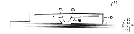
- FIG. 1 is a cross-sectional view illustrating a configuration of a main part of a lighting device in a ceiling light as a lighting device according to an embodiment of a lighting device including a lighting device according to the present invention.
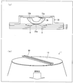
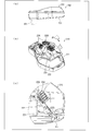
- (A) is a perspective view from the surface side which shows the structure of the said ceiling light
- (b) is a perspective view from the back surface side which shows the structure of the said ceiling light. It is a perspective view which shows the structure of the light source module in the said illuminating device.
- FIG. 1 is sectional drawing which shows an optical path when the light radiate
- (b) is the principal part which shows the optical path near a light emission part It is sectional drawing.
- (A) is sectional drawing which shows the optical path when the light radiate
- (b) is principal part cross section which shows the optical path near a light emission part.
- (A) is sectional drawing which shows the optical path when the light radiate
- (B) is a perspective view which shows the strip
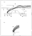
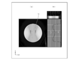
- (A) is a top view which shows the said light-guide plate,
- (b) is a graph which shows the luminance distribution on the string which passes along point A * B of (a).
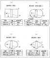
- (A) shows the structure of the modification of the said light-guide plate, Comprising: It is a top view which shows a rectangular light-guide plate, (b) is a top view which shows the light-guide plate which chamfered the rectangular corner
- FIG. 1 It is a perspective view which shows the structure of the modification of the light source module in the said illuminating device, Comprising: A frame-shaped light source module. It is sectional drawing which shows the toning illumination in the said illuminating device. It is a perspective view from the back side which shows the structure of the ceiling light which provided the radiation fin in the said illuminating device. It is a perspective view from the back side which shows the structure of the ceiling light in the case of adjusting input electric power in the center part and peripheral part of the said illuminating device. (A) is sectional drawing which shows the structure of the conventional lighting equipment, (b) is a top view which shows the structure of the lighting equipment, (c) is sectional drawing which shows the structure of the illuminating device in the lighting equipment.
- (D) is a plan view showing the configuration of the illumination device.
- (A) is a side view showing the configuration of another conventional lighting device,
- (b) is a perspective view showing the configuration of the other conventional lighting device, and
- (c) is another conventional lighting device. It is a perspective view which shows the principal part structure of this.
- FIGS. 1 to 13 An embodiment of the present invention will be described with reference to FIGS. 1 to 13 as follows.
- FIG. 1 is a cross-sectional view showing a configuration of a main part of a lighting device in a ceiling light.
- FIG. 2A is a perspective view showing the configuration of the ceiling light from the front side
- FIG. FIG. 3 is a perspective view from the back side showing the configuration of the ceiling light
- FIG. 3 is a perspective view from the front side showing the configuration of the light source module.
- the “front surface” direction is the direction of the light irradiation surface in the lighting device of the present invention
- the “back surface” direction is the opposite direction
- the “side surface” direction is The direction is orthogonal to both the front surface direction and the back surface direction. That is, when the lighting device of the present invention is installed as a ceiling light on the ceiling, the “front surface” is the room (floor) side, and the “back surface” is the ceiling side.
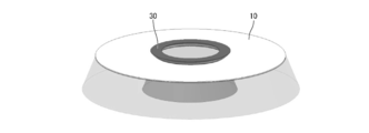
- the ceiling light 1 includes, for example, a disk-shaped lighting device 10, and the disk-shaped lighting device 10 includes a frame 20 on the outer periphery thereof.
- a light source module 30 is provided on the diameter of the disk as shown in FIG.
- the diameter of the ceiling light 1 is, for example, 550 mm, and the thinnest part is, for example, 10 mm.
- the shape and each dimension of the ceiling light 1 it is not restricted to this.
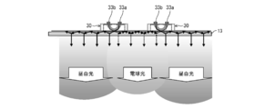
- the illuminating device 10 of the ceiling light 1 includes a diffusion sheet 11, an air layer 12, a light guide plate 13, and a light source module 30 provided in this order from the surface side as shown in FIG. 1.
- a portion of the back surface of the light guide plate 13 where the light source module 30 is not provided is provided with a reflection sheet 14 having an opening in that portion and a back chassis 15 as a metal chassis.
- the light source module 30 is provided with a sheet-shaped heat sink 32 on a light source holder 31 formed in a strip shape, and on the heat sink 32, a light emitting unit as a light source.
- LED boards 34a and 34b on which 33a and 33b (see FIG. 1) are mounted are provided.
- Spacers 36a and 36b are formed on the LED boards 34a and 34b to provide a gap between the LED boards 34a and 34b and the optical coupling member 35 described later. Due to this gap, it is possible to prevent the optical coupling member 35 from coming into contact with the light emitting portions 33a and 33b and damaging the light emitting portions 33a and 33b.
- the present invention is not limited to this, and the light emitting units 33a and 33b may be in close contact with the optical coupling member 35 as long as the light emitting units 33a and 33b are not damaged. Since the semiconductor light emitting part has a very fine size, the description of the light emitting part is omitted in FIG. 3 in order to prevent the drawing from being complicated. Moreover, in this Embodiment, although the light emission parts 33a * 33b are used as a light source, it is not necessarily this, For example, it is also possible to use an organic EL light emitting element or an inorganic EL light emitting element.
- the light emitting units 33a and 33b include a combination of a blue LED (Light Emitting Diode) chip and a yellow phosphor, a combination of a blue LED chip, a red phosphor and a green phosphor, It is composed of a combination of a blue LED chip, a red LED chip and a green LED chip, or an organic EL element.
- the light emitting sections 33a and 33b emit light having a color temperature of 2000K to 6000K. That is, red light in the morning sun or sunset has a color temperature of about 2000K, and sunlight has a color temperature of about 5000K to 6000K.
- a light emitting unit having a color temperature of 10,000 K to 20000 K is used as a light source used in a backlight of a liquid crystal display device.
- a plurality of the light emitting portions 33a and 33b are provided in parallel in two rows, and an optical coupling member 35 is provided above the light emitting portions 33a and 33b.
- the ceiling light 1 of the present embodiment includes a light guide plate 13 that irradiates light on the surface side, a light coupling member 35 as an optical element that couples light to the light guide plate 13, and the above
- the light coupling member 35 includes light emitting portions 33a and 33b that emit incident light, and the light guide plate 13, the light coupling member 35, and the light emitting portions 33a and 33b are arranged in this order from the front surface side to the back surface side of the lighting device 10. It consists of what is arranged. Therefore, the illuminating device 10 in the ceiling light 1 of the present embodiment is a illuminating device 10 directly under the light source in which the light emitting portions 33 a and 33 b are provided on the back side of the light guide plate 13.
- the optical coupling member 35 has a substantially semi-cylindrical cross section provided between the light guide plate 13 and the light emitting portions 33a and 33b. It consists of a strip-shaped body, that is, a rod-shaped body having a substantially U-shaped cross section.
- the material of the optical coupling member 35 is made of the same resin as that of the light guide plate 13. If the same material is used, the refractive index can be made the same, so that light is smoothly incident on the light guide plate 13 from the optical coupling member 35.
- the refractive index of the light guide plate 13 may be slightly higher than the refractive index of the optical coupling member 35.
- the material is not limited to resin, and a material such as glass may be used.
- the efficiency of coupling to the optical coupling member 35 can be improved by controlling the light distribution by forming a side wall (not shown) with a white resin or the like around the light emitting sections 33a and 33b.
- the optical coupling member 35 has a top flat surface 35a that abuts the flat light guide plate 13 on the surface of the optical coupling member 35 on the light guide plate 13 side.
- the top flat surface 35a has curved surfaces 35b and 35c on both ends.
- the curved surfaces 35b and 35c can be, for example, a cross-sectional parabola shown in FIG. However, it is not necessarily limited to this, and as shown in FIGS. 5 (a) and 5 (b), it may be an ellipse in cross section. In addition, a curved shape such as an arch shape, or oblique from the top flat surface 35a. Even if it is a plane inclined in a straight line, any shape that can effectively couple light to the light guide plate may be used.
- the surface of the optical coupling member 35 opposite to the light guide plate 13 side, that is, the lower end of the optical coupling member 35 is a lower flat surface 35d as shown in FIG.
- the spacers 36a and 36b described above are formed, and serve as spacers that prevent the light emitting portions 33a and 33b and the optical coupling member 35 from colliding with each other.
- the light emitting portions 33a and 33b are bonded to the LED substrates 34a and 34b, respectively.
- the spacers 36a and 36b are adhesively fixed to the LED boards 34a and 34b by applying an adhesive or the like.
- the light emitting portions 33a and 33b have a slight gap between them and the optical coupling member 35.
- the present invention is not limited to this, and the light emitting portions 33a and 33b are not limited thereto.
- the light emitting sections 33a and 33b may be in close contact with the optical coupling member 35 as long as the range does not damage 33b.
- a concave portion 35e is formed in the central portion on the lower end side of the optical coupling member 35.
- the configuration is not limited to this, and the concave portion 35e may not be present, and the optical coupling member 35 may have a substantially semicircular cross section. That is, in the present embodiment, it is only necessary to secure an optical path to the light guide plate 13 for the light reflected by the curved surfaces 35b and 35c. Therefore, a portion that does not become the optical path can be cut out as a recess 35e. Thereby, cost reduction and weight reduction can be achieved. It is also possible to provide a reflection means such as a reflection sheet (not shown) in the recess 35e. Thereby, even if stray light may be generated in the vicinity of the top flat surface 35a, a part of the stray light can be reflected to the light guide plate 13 side to improve irradiation on the surface side.
- Light emitting portions 33a and 33b are provided close to the optical coupling member 35 on the lower side (back side) of the lower flat surfaces 35d and 35d of the optical coupling member 35, respectively. As shown in FIGS. 4B and 5B, these light emitting portions 33a and 33b are arranged on the end side (side surface side) with respect to the focal position F of the curved surfaces 35b and 35c having a cross-section parabola or a cross-section ellipse. It is preferable that it exists in. Thereby, for example, as shown in FIG.
- light emitted from the light emitting portion 33 a is reflected by the curved surface 35 b of the parabolic parabola of the optical coupling member 35, and the reflected light is reflected by the optical coupling member 35. It reaches the top flat surface 35a, and enters the light guide plate 13 obliquely while maintaining the arrival direction. Then, the light incident on the light guide plate 13 is reflected by the inside of the right side of the light guide plate 13 shown in FIG. The angle of traveling through the light guide plate 13 is changed by colliding with a light scatterer, and the total reflection condition is broken, the light is emitted from the light guide plate 13, reflected by the reflection sheet 14, and further passed through the light guide plate 13.
- FIG. 6A schematically shows a state in which light from the left and right light emitting portions 33a and 33b passes through the optical coupling member 35, enters the light guide plate 13, and is totally reflected and propagated therein. It is.
- Such an optical path is the same in the optical coupling member 35 having an elliptical cross section shown in FIGS.
- the cross-sectional ellipse can be coupled so that the light is focused and incident on the light guide plate 13, so that the coupling efficiency can be increased.
- the strip-shaped light source module 30 is crossed over the central portion of the disc-shaped ceiling light 1, that is, the center line.
- FIG. 7 (a) the chord passing through the points A and B, which are ⁇ 1/3 of the radius in the X-axis direction from the center of the light guide plate 13, as shown in FIG. Light emitted from the light guide plate 13 having the luminance distribution shown can be obtained.
- the ceiling light 1 of the present embodiment can obtain a uniform and smooth luminance distribution.
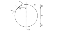
- the light P emitted from the light source module 30 provided on the center line reaches the outer peripheral end 13a.
- the light guide plate 13 of the present embodiment is made of, for example, an acrylic plate
- the radial direction (normal direction to the tangent line Q) at the outer peripheral end 13a is orthogonal to the light source module 30 according to Snell's law.
- the angle ⁇ formed by the direction is divided into a region S1 that is not totally reflected and regions S2 and S2 that are totally reflected with a boundary of about 42 degrees.
- the region S1 that is not totally reflected is a central side portion of the diameter, and the regions S2 and S2 that are totally reflected are both side portions of the diameter. For this reason, in the present embodiment, the brightness of the entire light guide plate 13 is further uniformed by adjusting the arrangement pattern of the light scattering portion which is an optical path conversion element (not shown).
- the illuminating device 10 of this Embodiment As shown in FIG. 1, the light of light emission part 33a * 33b is entered from the back surface side of the light-guide plate 13. As shown in FIG.
- a side edge type backlight has been conventionally used.
- the light utilization efficiency of the conventional side edge type backlight is 75%.
- the light use efficiency of the lighting apparatus 10 of the present embodiment was 88%.
- the illuminating device 10 of this Embodiment is excellent in light utilization efficiency rather than the conventional side edge type
- the linear expansion accompanying the temperature rise in the longitudinal direction of the light guide plate is large, it is necessary to provide a gap between the LED chip and the light guide plate. As a result, the LED chip Since the emitted light from the light leaks from this gap, the light utilization efficiency could not be increased.
- the light emitting portions 33a and 33b are provided immediately below the light guide plate 13, the expansion dimension is small even when the light guide plate 13 is thermally expanded. Therefore, since it is not necessary to provide a gap, the light utilization efficiency can be increased.
- the illumination device 10 of the present embodiment unlike the conventional side-edge type backlight, there is no light source at the end of the ceiling light 1 as shown in FIG. It is possible to provide the frame 20 directly at the end of the frame. As a result, surface light emission with a frame size of 6 mm or less is possible. Further, by forming the frame 20 from a transparent, translucent or milky white resin material, it is possible to emit light from the entire surface including the frame 20. By optimizing the shape and material of the frame 20, indirect illumination that emits light in the back surface direction is possible.
- the illumination device 10 has a disk shape, for example.
- the present invention is not limited to this, and various shapes may be used as shown in FIGS. 9 (a) to 9 (d). it can.
- FIG. 9A shows a rectangular light guide plate 13
- FIG. 9B shows a light guide plate 13 with rectangular corners chamfered
- FIG. 9C shows an elliptical guide
- FIG. 9D shows a light guide plate 13 which is a diamond-shaped light guide plate 13.
- the amount of light in the light guide direction of the light from the light source module 30, that is, the direction orthogonal to the light source module 30 extending in a strip shape (traveling direction) is Decrease gradually.
- the distribution of the dot pattern of the light scattering portion can obtain a uniform luminance distribution from the light guide plate 13 to the surface side by increasing the number of dot patterns as it goes in the traveling direction.
- the amount of light is constant, and as a result, the distribution of the dot pattern of the light scattering portion is also uniform.
- the rectangular portion is the same as FIG. 9A. That is, the amount of light gradually decreases in the light guide direction (traveling direction) of light from the light source module 30. For this reason, the distribution of the dot pattern of the light scattering portion can obtain a uniform luminance distribution from the light guide plate 13 to the surface side by increasing the number of dot patterns as it goes in the traveling direction. In the direction perpendicular to the light guide direction (vertical direction), the amount of light is constant, and as a result, the dot pattern distribution in the light scattering portion is also uniform.
- the light quantity gradually decreases in the light guide direction (traveling direction) of the light from the light source module 30.
- the distribution of the dot pattern of the light scattering portion can obtain a uniform luminance distribution from the light guide plate 13 to the surface side by increasing the number of dot patterns as it goes in the traveling direction.
- the light is totally reflected.
- the light proceeds in the vertical direction. Accordingly, it is necessary to reduce the dot pattern of the light scattering portion.
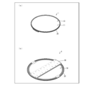
- the light source module 30 of the illuminating device 10 is provided in strip
- it can be a ring shape that is a frame shape.
- the frame-shaped light source module 30 that follows the shape of the illumination device 10, it is possible to easily achieve uniform luminance.
- the light source module 30 is provided with two rows of light emitting portions 33a and 33b along the longitudinal direction of the optical coupling member 35. Therefore, by adjusting the color temperatures of the light emitting sections 33a and 33b in the two rows, as shown in FIG. 11, dimming and toning illumination can be performed.
- the light emitting unit 33a is daylight white and the light emitting unit 33b is a light bulb color. Thereby, it is possible to perform dimming and toning illumination such as irradiating daylight white light outside the ceiling light 1 and illuminating a light bulb color inside the ceiling light 1.
- the light source modules 30 are provided in one row, but the present invention is not necessarily limited to this, and a plurality of rows may be provided. Thereby, improvement in brightness and dimming illumination are possible.
- the light emitting sections 33 a and 33 b are arranged so that the optical axis direction of the emitted light toward the optical coupling member 35 is orthogonal to the light guide plate 13. For this reason, since it is not necessary to arrange the light emitting portions 33a and 33b obliquely with respect to the flat light guide plate 13, the light emitting portions 33a and 33b can be easily arranged and the structure is simple.
- the light emitting units 33a and 33b emit light having a color temperature of 2000K to 6000K. For this reason, it can be appropriately used as an illumination device such as the ceiling light 1.
- the illuminating device 10 that can uniformly irradiate the entire light guide plate 13 without increasing the number of the light emitting portions 33a and 33b and processing the light guide plate.
- the light guide plate 13 is not processed and light is incident from below, so that the light guide plate 13 and the ceiling light 1 can be thinned. Specifically, a certain amount of thickness is required for processing the light guide plate 13. In this case, for example, when an edge light type light guide plate is considered, if the light guide plate 13 is made thinner than the widths of the light emitting portions 33a and 33b, the optical coupling rate is lowered, so that there is a limit to thinning. In this regard, in the present embodiment, if the light guide plate 13 is thinned, the ceiling light 1 is thinned. Moreover, since the material of the light guide plate 13 can be saved, the cost can be reduced.
- the light emitting portions 33a and 33b may be mounted so that the optical axis thereof is perpendicular to the light guide plate 13, the assembly is simple. That is, in the case of the conventional edge light, since it is necessary to attach the light emitting parts 33a and 33b from the side surfaces, the manufacture becomes somewhat difficult.
- the optical coupling member 35 is provided in a band shape.
- the optical coupling member 35 may be a double row. In this case, in particular, it is preferable to arrange them symmetrically with respect to the vertical or horizontal center line of the light guide plate 13 so that the luminance distribution of the double-row optical coupling members 35 is symmetrical. Further, when the optical coupling members 35 are in a double row, the luminance of light emitted from the surface of the light guide plate 13 is such that the luminance at the center of the flat light guide plate 13 is higher than the luminance at the end of the light guide plate 13. It is desirable to arrange in.
- the optical coupling member 35 is provided on the center line in the vertical or horizontal direction of the flat light guide plate 13. This makes it possible to make the luminance symmetric about the vertical or horizontal center line of the light guide plate 13 as an axis. Therefore, it is possible to provide the lighting device 10 suitable for the luminance distribution.
- the light source includes a plurality of light emitting units 33a and 33b.
- the light emitting units 33a and 33b have lower power consumption and lower heat generation than incandescent bulbs, and can save energy.
- the ceiling light 1 as the lighting fixture of the present embodiment includes a lighting device 10.
- the ceiling light 1 provided with the illuminating device 10 which enables uniform irradiation in the whole light-guide plate 13 without the increase in the number of light emission parts 33a * 33b and the process of the light-guide plate 13 can be provided. .
- a back chassis 15 that is a flat chassis that holds the light guide plate 13 in a flat surface is provided below the light guide plate 13, and the back chassis 15 is guided.
- the optical plate holding surface has an opening at a portion where the optical coupling member 35 contacts the light guide plate 13, and the optical coupling member 35 and the light emitting portions 33 a and 33 b are positioned below the light guide plate holding surface of the back chassis 15. Yes.
- the optical coupling member 35 and the light emitting portions 33a and 33b protrude on the back surface side of the light guide plate 13. Accordingly, it is possible to reduce the thickness of portions other than the optical coupling member 35 and the light emitting portions 33a and 33b. For this reason, the overall thickness can be reduced. Further, by adopting such a configuration, the heat radiation of the light emitting portions 33a and 33b is excellent. Moreover, since the back chassis 15 functions as a heat sink by connecting the light source module 30 to the back chassis 15, high heat dissipation performance can be obtained. As a result, the light emission efficiency of the light emitting units 33a and 33b is also improved.
- the light emitting portions 33 a and 33 b are arranged in two rows along the longitudinal direction of the optical coupling member 35. Specifically, the light emitting units 33a and 33b are provided in two rows in parallel along the center line directly below both ends of the lower end chord in the optical coupling member 35 having a semicircular cross section.
- the light emitting portions 33a and 33b of the two rows emit light in opposite directions, so that the line passing through the midpoint between the two rows is axially symmetric and both sides of the optical coupling member 35 That is, the light can be guided to both ends of the light guide plate 13.
- the line passing through the midpoint between the two rows coincides with the center line of the light guide plate 13
- the light guide plate is guided to both ends of the light guide plate with the center line of the light guide plate 13 being axially symmetrical.
- a luminance distribution that is axially symmetric about the 13 center lines can be obtained. Therefore, the luminance distribution can be made uniform in the light guide plate 13 with a simple structure. That is, when the light emitting part 33a is used alone, there is a possibility that the light above the light emitting part 33a does not transmit light and becomes a dark part. This can be supplemented with light from the other light emitting section 33b.
- the diffusion sheet 11 is not stuck with respect to the light-guide plate 13, and an air layer is provided between the diffusion sheet 11 and the light-guide plate 13.
- FIG. 12 is provided.
- the illumination device 10 of the present embodiment can be applied to a large planar light source as it is, and can provide a large ceiling light 1. Furthermore, since no member is required around the light guide plate 13, it can be applied to a larger ceiling light 1 by arranging them seamlessly.
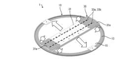
- the illuminating device 10 of this Embodiment is from the integrated thing which supports the some light emission part 33a * 33b and the some light emission part 33a * 33b, and radiates the heat
- the illumination device 10 has a disk shape, and a plurality of light emitting portions 33a and 33b are arranged on the center line of the disk.
- the distance from the light source module 30 provided on the center line in the direction orthogonal to the disk-shaped center line to the outer peripheral end 13a that is an arc is the central portion on the disk-shaped center line.
- the distance from the non-total reflection region S1 to the arc is longer than the distance from the total reflection regions S2 and S2, which are the end portions on the center line of the disk shape, to the arc.
- the metal chassis has a larger radiation area in the light emitting portions 33a and 33b arranged in the central portion on the disc-shaped center line than the plurality of light emitting portions 33a and 33b arranged on the disc-shaped center line. In the light emitting portions 33a and 33b arranged at the end portions on the center line of the disk shape, the radiation area is small. Therefore, the back chassis 15 is different in heat radiation area from the light emitting portions 33a and 33b.
- a heat uniform radiation means for ensuring the uniformity of heat radiation in the entire region of the back chassis 15 is provided.
- the back chassis 15 is formed as a single unit with respect to the plurality of light emitting units 33a and 33b arranged side by side, so that the back chassis 15 is not provided for each of the light emitting units 33a and 33b. .
- the lighting device 10 that can uniformly dissipate the plurality of light emitting portions 33a and 33b and thereby suppress a decrease in lifetime without increasing the number of parts and complicating the manufacturing process. .
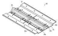
- the heat uniform radiation means includes heat radiation fins 31a and 31a provided in a small area of the heat radiation area for the plurality of light emitting portions 33a and 33b in the back chassis 15. can do. That is, heat radiation fins (fin) 31 a and 31 a are provided at both ends of the light source holder 31 of the light source module 30 integrated with the back chassis 15.
- the heat radiating fins 31a and 31a are formed, for example, by a plurality of ribs standing on a metal flat plate such as aluminum (Al).
- the heat of the light emitting portions 33a and 33b can be efficiently radiated by the heat radiating fins 31a and 31a as the uniform heat radiation means.
- the radiating fins 31 a and 31 a are provided in a region where the heat radiation region for the light emitting portions 33 a and 33 b in the back chassis 15 is small. For this reason, uniform heat dissipation of the plurality of light emitting units 33a and 33b can be performed.
- the heat radiating fins 31a are disposed only in the peripheral portion of the ceiling light 1, but may be disposed in a region toward the center in addition to the peripheral portion. With this arrangement, the heat dissipation performance can be further improved.
- a heat radiation sheet made of a silicone material or a graphite material may be interposed between the back chassis 15 and the heat radiation fins 31a.
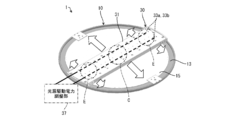
- the uniform heat radiation means includes the light emitting sections 33a according to the size of the heat radiation area for the plurality of light emitting sections 33a and 33b in the back chassis 15, as shown in FIG. It can be assumed that the light source drive power adjustment unit 37 is used as light source power adjustment means for reducing the output power to 33b. The light source driving power adjustment unit 37 is actually mounted inside the light source holder 31.
- heat dissipation from the light emitting portions 33 a and 33 b of the peripheral portions E and E to the back chassis 15 in the disk-shaped lighting device 10 which is both ends in the longitudinal direction of the light source holder 31 is a heat radiation region. Therefore, the driving power of the light emitting portions 33a and 33b existing in the peripheral portions E and E is small.
- the heat dissipation from the light emitting portions 33a and 33b in the central portion C in the longitudinal direction of the light source holder 31 to the back chassis 15 is a region having a large heat radiation region, and thus the light emitting portions 33a and.
- the drive power of 33b is large.
- the light source driving power adjusting unit 37 as the uniform heat radiation means changes the output power to the light emitting units 33a and 33b according to the size of the heat radiation area for the plurality of light emitting units 33a and 33b in the back chassis 15. It can be adjusted to be large or small. Therefore, it is possible to provide the lighting device 10 that can uniformly dissipate the plurality of light emitting units 33a and 33b and thereby suppress the reduction of the lifetime.
- the lighting device 10 of the present embodiment includes a flat light guide plate 13 and a plurality of light emitting units 33a and 33b arranged on the back side of the light guide plate 13, and the light emitting units 33a and 33b
- the emitted light is incident on the light guide plate 13, and the incident light is totally reflected inside the light guide plate 13 and guided from the surface side of the light guide plate 13 while being guided.
- An optical coupling member 35 that couples light emitted from the light emitting portions 33a and 33b so that light is incident obliquely on the light guide plate 13 is provided between the light guide plate 13 and the light emitting portions 33a and 33b. It has been.
- the back chassis 15 is integrally provided on the back surface of the light guide plate 13 and the back surfaces of the light emitting portions 33a and 33b.
- the illuminating device 10 that can uniformly irradiate the entire light guide plate 13 without increasing the number of the light emitting portions 33a and 33b and processing the light guide plate.
- the lighting device 10 of the present embodiment includes the lighting device 10 described above. Therefore, the ceiling light provided with the lighting device 10 that can uniformly dissipate the light emitting portions 33a and 33b and suppress the decrease in the lifetime without increasing the number of parts and complicating the manufacturing process. 1 can be provided.
- heat from the light source can be efficiently radiated by applying an alumite treatment or heat radiation paint using heat radiation on the surface of the back chassis 15 or the heat radiation fin 31a of the present embodiment.
- the uniform heat radiation means can be composed of heat radiation fins provided in a small heat radiation area for the plurality of light sources in the metal chassis. is there.
- the heat of the light source can be efficiently radiated by the radiating fin as the uniform heat radiation means.
- the radiation fin is provided in the area
- the heat uniform radiation means includes light source power adjustment means that increases or decreases the output power to each light source according to the size of the heat radiation area for the plurality of light sources in the metal chassis. can do.
- the light source power adjusting means as the heat uniform radiation means can adjust the output power to each light source according to the size of the heat radiation area for the plurality of light sources in the metal chassis.
- the illuminating device of the present invention includes a flat light guide plate and the plurality of light sources arranged on the back side of the light guide plate.
- the light emitted from the light source is incident on the light guide plate.
- Optical coupling that couples the light emitted from the light source so that light is incident on the light guide plate obliquely while being irradiated from the surface side of the light guide plate while being totally reflected inside the light guide plate and guiding the light.
- a member may be provided between the light guide plate and the light source, and the metal chassis may be provided integrally on the back surface of the light guide plate and the back surface of the light source.
- an optical coupling member that couples light emitted from the light source so that light is incident on the light guide plate obliquely.
- the light emitted from the light source on the back surface of the light guide plate is coupled to the light guide plate through the optical coupling member and is incident obliquely, and moves to the end of the light guide plate while totally reflecting the inside of the light guide plate.
- the total reflection condition is broken by the optical path conversion element, and the light is emitted to the surface side of the light guide plate.
- the present invention by providing an optical coupling member separate from the light guide plate, light is incident obliquely on the flat light guide plate and totally reflected inside the light guide plate to be guided to the whole. be able to. As a result, even if the light guide plate is not processed, incident light from the light source can be guided inside the light guide plate via the optical coupling member, and light can be irradiated uniformly from the light guide plate.
- the lighting device of the present invention and the lighting device including the lighting device can be applied to ceiling-mounted ceiling lights, wall lighting attached to a wall surface, signboards, and the like. And as an application field, it can apply to various lighting fixtures, such as facilities, such as a store and an office, and business.
Landscapes
- Engineering & Computer Science (AREA)
- General Engineering & Computer Science (AREA)
- Physics & Mathematics (AREA)
- General Physics & Mathematics (AREA)
- Optics & Photonics (AREA)
- Planar Illumination Modules (AREA)
- Arrangement Of Elements, Cooling, Sealing, Or The Like Of Lighting Devices (AREA)
Abstract
La présente unité d'éclairage (10) comprend : des sections d'émission de lumière (33a, 33b) ; et un châssis arrière formé d'un seul bloc (15) supportant les sections d'émission de lumière (33a, 33b) et permettant le rayonnement de la chaleur transférée depuis les sections d'émission de lumière (33a, 33b). Les sections d'émission de lumière (33a, 33b) sont disposées côte à côte sur un élément de support de source lumineuse (31) intégré au châssis arrière (15). Le châssis arrière (15) comprend une région de rayonnement de chaleur différente pour chacune des sections d'émission de lumière (33a, 33b). Des ailettes de rayonnement de chaleur (31a, 31a), par exemple, sont disposées sur le châssis arrière (15), les ailettes de rayonnement de chaleur (31a, 31a) servant de moyen de rayonnement uniforme de la chaleur afin de garantir l'uniformité de rayonnement de la chaleur dans toute la région du châssis arrière (15).
Applications Claiming Priority (2)
| Application Number | Priority Date | Filing Date | Title |
|---|---|---|---|
| JP2011093409A JP2012226967A (ja) | 2011-04-19 | 2011-04-19 | 照明装置、及びそれを備えた照明機器 |
| JP2011-093409 | 2011-04-19 |
Publications (1)
| Publication Number | Publication Date |
|---|---|
| WO2012144394A1 true WO2012144394A1 (fr) | 2012-10-26 |
Family
ID=47041505
Family Applications (1)
| Application Number | Title | Priority Date | Filing Date |
|---|---|---|---|
| PCT/JP2012/059939 Ceased WO2012144394A1 (fr) | 2011-04-19 | 2012-04-11 | Unité d'éclairage et dispositif d'éclairage associé |
Country Status (2)
| Country | Link |
|---|---|
| JP (1) | JP2012226967A (fr) |
| WO (1) | WO2012144394A1 (fr) |
Cited By (1)
| Publication number | Priority date | Publication date | Assignee | Title |
|---|---|---|---|---|
| FR2995971A1 (fr) * | 2012-09-26 | 2014-03-28 | Valeo Vision | Dispositif d'eclairage, notamment pour vehicule automobile. |
Citations (4)
| Publication number | Priority date | Publication date | Assignee | Title |
|---|---|---|---|---|
| JP2000030521A (ja) * | 1998-07-08 | 2000-01-28 | Mitsubishi Electric Corp | 面発光光源 |
| JP2009075565A (ja) * | 2007-07-29 | 2009-04-09 | Cree Inc | Lcdディスプレイ用のledバックライト・システム |
| JP2010049994A (ja) * | 2008-08-22 | 2010-03-04 | Panasonic Corp | バックライト装置及び液晶表示装置 |
| WO2011040089A1 (fr) * | 2009-10-02 | 2011-04-07 | シャープ株式会社 | Dispositif d'éclairage et dispositif d'affichage |
-
2011
- 2011-04-19 JP JP2011093409A patent/JP2012226967A/ja active Pending
-
2012
- 2012-04-11 WO PCT/JP2012/059939 patent/WO2012144394A1/fr not_active Ceased
Patent Citations (4)
| Publication number | Priority date | Publication date | Assignee | Title |
|---|---|---|---|---|
| JP2000030521A (ja) * | 1998-07-08 | 2000-01-28 | Mitsubishi Electric Corp | 面発光光源 |
| JP2009075565A (ja) * | 2007-07-29 | 2009-04-09 | Cree Inc | Lcdディスプレイ用のledバックライト・システム |
| JP2010049994A (ja) * | 2008-08-22 | 2010-03-04 | Panasonic Corp | バックライト装置及び液晶表示装置 |
| WO2011040089A1 (fr) * | 2009-10-02 | 2011-04-07 | シャープ株式会社 | Dispositif d'éclairage et dispositif d'affichage |
Cited By (2)
| Publication number | Priority date | Publication date | Assignee | Title |
|---|---|---|---|---|
| FR2995971A1 (fr) * | 2012-09-26 | 2014-03-28 | Valeo Vision | Dispositif d'eclairage, notamment pour vehicule automobile. |
| WO2014048847A1 (fr) * | 2012-09-26 | 2014-04-03 | Valeo Vision | Dispositif d'éclairage, notamment pour véhicule automobile |
Also Published As
| Publication number | Publication date |
|---|---|
| JP2012226967A (ja) | 2012-11-15 |
Similar Documents
| Publication | Publication Date | Title |
|---|---|---|
| US8297797B2 (en) | Lighting apparatus | |
| CN103339436B (zh) | Led照明装置 | |
| CN101975345B (zh) | Led日光灯 | |
| TWI509187B (zh) | 照明器具 | |
| CN101922633A (zh) | Led照明装置 | |
| JP2013500560A (ja) | ランプ | |
| CN102348928A (zh) | 发光模块及照明器具 | |
| KR20100115864A (ko) | 눈부심 방지 기능을 가진 엘이디 조명 램프 | |
| WO2013145049A1 (fr) | Lampe | |
| JP5133439B2 (ja) | 照明装置、及びそれを備えた照明機器 | |
| WO2012144393A1 (fr) | Dispositif d'éclairage et appareil d'éclairage le comportant | |
| WO2012144394A1 (fr) | Unité d'éclairage et dispositif d'éclairage associé | |
| JP2012226966A (ja) | 照明装置、及びそれを備えた照明機器 | |
| JP2012226965A (ja) | 照明装置、及びそれを備えた照明機器 | |
| KR101220909B1 (ko) | 형광등형 엘이디 조명등 | |
| TWI409412B (zh) | Led照明裝置 | |
| WO2016107513A1 (fr) | Structure d'ampoule de lampe à diode électroluminescente | |
| TWI442004B (zh) | 光源模組 | |
| CN101725901A (zh) | 光源模组 | |
| JP2012204218A (ja) | 照明装置、及びそれを備えた照明機器 | |
| TWI402454B (zh) | Led日光燈 | |
| TWI393842B (zh) | Led照明裝置 | |
| JPWO2017002960A1 (ja) | 照明装置 | |
| JP2012204217A (ja) | 照明装置、及びそれを備えた照明機器 | |
| TWI516719B (zh) | 燈具 |
Legal Events
| Date | Code | Title | Description |
|---|---|---|---|
| 121 | Ep: the epo has been informed by wipo that ep was designated in this application |
Ref document number: 12773664 Country of ref document: EP Kind code of ref document: A1 |
|
| NENP | Non-entry into the national phase |
Ref country code: DE |
|
| 122 | Ep: pct application non-entry in european phase |
Ref document number: 12773664 Country of ref document: EP Kind code of ref document: A1 |