WO2012144550A1 - Capteur du type à capacité - Google Patents
Capteur du type à capacité Download PDFInfo
- Publication number
- WO2012144550A1 WO2012144550A1 PCT/JP2012/060551 JP2012060551W WO2012144550A1 WO 2012144550 A1 WO2012144550 A1 WO 2012144550A1 JP 2012060551 W JP2012060551 W JP 2012060551W WO 2012144550 A1 WO2012144550 A1 WO 2012144550A1
- Authority
- WO
- WIPO (PCT)
- Prior art keywords
- electrode pair
- capacitance
- electrode
- group
- external force
- Prior art date
- Legal status (The legal status is an assumption and is not a legal conclusion. Google has not performed a legal analysis and makes no representation as to the accuracy of the status listed.)
- Ceased
Links
Images






Classifications
-
- H—ELECTRICITY
- H03—ELECTRONIC CIRCUITRY
- H03K—PULSE TECHNIQUE
- H03K17/00—Electronic switching or gating, i.e. not by contact-making and –breaking
- H03K17/94—Electronic switching or gating, i.e. not by contact-making and –breaking characterised by the way in which the control signals are generated
- H03K17/96—Touch switches
- H03K17/962—Capacitive touch switches
-
- G—PHYSICS
- G01—MEASURING; TESTING
- G01L—MEASURING FORCE, STRESS, TORQUE, WORK, MECHANICAL POWER, MECHANICAL EFFICIENCY, OR FLUID PRESSURE
- G01L1/00—Measuring force or stress, in general
- G01L1/14—Measuring force or stress, in general by measuring variations in capacitance or inductance of electrical elements, e.g. by measuring variations of frequency of electrical oscillators
- G01L1/142—Measuring force or stress, in general by measuring variations in capacitance or inductance of electrical elements, e.g. by measuring variations of frequency of electrical oscillators using capacitors
- G01L1/146—Measuring force or stress, in general by measuring variations in capacitance or inductance of electrical elements, e.g. by measuring variations of frequency of electrical oscillators using capacitors for measuring force distributions, e.g. using force arrays
Definitions
- the present invention when an external force is applied to a capacitive sensor formed by interposing an elastically deformable dielectric layer between opposing electrode pairs, an electrostatic force that changes as the dielectric layer deforms is applied.
- the present invention relates to a capacitance type sensor device that can measure the position and magnitude of the external force by measuring the capacitance.
- a touch sensor using a capacitance is described in International Publication No. 2009/013965.
- This touch sensor detects a capacitance between the arranged electrodes and the ground. For example, the position of the approaching finger is detected by utilizing the fact that the capacitance of the approaching electrode and the ground changes by bringing a human finger closer.
- Japanese Patent Publication No. 6-52206 discloses a device for measuring the distribution of external force applied by measuring the capacitance between electrode pairs for a capacitance type sensor.
- the dielectric layer can be elastically deformed when subjected to an external force. It is necessary to have a thickness. When the thickness of the dielectric layer is ensured, the distance between the electrode pairs increases. When the distance between the electrode pairs increases, when an external force is applied and the dielectric layer elastically deforms, the capacitance between the electrode pairs changes as the distance between the electrode pairs decreases. Small change in capacitance. Therefore, the resolution of the magnitude of the external force that can be detected becomes low, and the magnitude of the external force cannot be detected with high accuracy.
- This invention is made in view of such a situation, and it aims at providing the electrostatic capacitance type sensor apparatus which can detect the position and magnitude
- the capacitive sensor device is an electrostatic sensor in which electrode pairs provided facing each other at a distance are arranged in a matrix, and an elastically deformable dielectric layer is arranged between the electrode pairs.
- a capacitance-type sensor, and a capacitance measuring unit that performs measurement of capacitance between the electrode pair group including a plurality of electrode pairs including the selected electrode pair for the electrode pair group including a plurality of combinations;
- An external force calculation unit that calculates the magnitude of the external force applied to the position of the selected electrode pair based on the plurality of measured capacitances.
- the capacitance between the electrode pair changes as the distance between the electrode pair changes as the dielectric layer is elastically deformed by an external force. Using this, the position and magnitude of the external force are acquired.
- the electrostatic capacitance measurement part in this means is measuring the electrostatic capacitance of the electrode pair group comprised from a some electrode pair instead of measuring the electrostatic capacitance for each electrode pair. Accordingly, the area of the electrode pair at the time of measurement is not the area of one electrode pair but the area of a plurality of electrode pairs. Here, the capacitance increases as the area of the electrode pair increases. Therefore, by measuring the capacitance of the electrode pair group, the measured capacitance outputs a larger value than when measuring the capacitance of one electrode pair. Therefore, the measured capacitance is highly accurate.
- the capacitance is measured for a plurality of combinations of the electrode pair group including the selected electrode pair. That is, the selected electrode pair is included in an electrode pair group composed of a plurality of combinations. Accordingly, the capacitances of these electrode pairs are all values affected by the capacitance of the selected electrode pair.
- the magnitude of the external force applied to the position of the selected electrode pair is calculated based on the capacitance of the electrode pair group consisting of a plurality of combinations.
- the capacitance of the selected electrode pair is proportional to the magnitude of the external force applied to the selected electrode pair. Therefore, the external force calculation unit calculates the external force as a value proportional to the capacitance of the selected electrode pair using the capacitance of the plurality of electrode pair groups. For example, in consideration of the influence degree of the selected electrode pair in the electrode pair group, the influence degree of the capacitance of each electrode pair group is determined, and the external force applied to the selected electrode pair is determined. Calculate the size. Therefore, it is possible to detect the external force received by each electrode pair constituting the electrode pair group. That is, the magnitude and position of the external force applied to the matrix capacitive sensor can be obtained with high accuracy and high resolution.
- the capacitance type sensor includes a first electrode group in which a plurality of first electrodes extending in a first direction are arranged in a second direction orthogonal to the first direction, and a second electrode extending in the second direction.
- a plurality of electrodes arranged in one direction, the second electrode group disposed opposite to the first electrode group at a distance, and the second electrode group disposed between the first electrode group and the second electrode group A dielectric layer may be provided. Thereby, the number of electrodes and the number of wirings can be reduced.
- the electrode pair group for measuring the capacitance in the capacitance measuring unit may be composed of a plurality of continuous electrode pairs. Thereby, the influence degree of the selected electrode pair in the electrode pair group can be determined relatively easily. That is, it can be obtained with high accuracy by simple calculation.
- the electrode pair group measured by the capacitance measuring unit may be the electrode pair group not including the electrode pair constituting the electrode pair group measured immediately before.
- the electrode pair group is charged by the capacitance measurement. If the electrode pair group measured immediately before and the electrode pair group measured this time overlap, the capacitance of the electrode pair group measured this time may be affected by the charge charged in the electrode pair group by the previous measurement. There is.
- the electrode pair group measured immediately before and the electrode pair group measured this time do not overlap. Therefore, the capacitance of the electrode pair group measured this time can reduce the influence of the charge charged in the electrode pair group by the previous measurement. As a result, the capacitance of the electrode pair group measured this time can be measured with high accuracy. As a result, the position and magnitude of the external force applied to the capacitive sensor can be calculated with high accuracy.
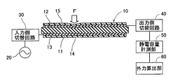
- 1st embodiment It is a figure which shows the structure of an electrostatic capacitance type sensor apparatus, and shows sectional drawing of an electrostatic capacitance type sensor. It is a figure which shows the structure of an electrostatic capacitance type sensor apparatus, and is a figure which shows the detailed structure of an electrostatic capacitance type sensor, an input side switching circuit, and an output side switching circuit.
- the capacitive sensor is a plan view in a state where an insulating layer is removed.
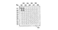
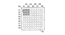
- 1st embodiment The top view of an electrostatic capacitance type sensor is shown, and the electrode pair group of an electrostatic capacitance type sensor at the time of measuring by an electrostatic capacitance measurement part by hatching is shown.
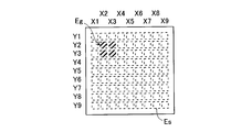
- the top view of an electrostatic capacitance type sensor is shown, and the electrode pair group of an electrostatic capacitance type sensor at the time of measuring by an electrostatic capacitance measurement part in the next measurement order of FIG. 3A by hatching is shown.
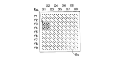
- the top view of an electrostatic capacitance type sensor is shown, and the electrode pair group of an electrostatic capacitance type sensor at the time of measuring by an electrostatic capacitance measurement part in the next measurement order of FIG. 3B by hatching is shown.
- the top view of an electrostatic capacitance type sensor is shown, and the electrode pair group of an electrostatic capacitance type sensor at the time of measuring by an electrostatic capacitance measurement part in the next measurement order of FIG. 3C by hatching is shown.
- 2nd embodiment The top view of a capacitive sensor is shown, and the electrode pair group of a capacitive sensor at the time of measuring by a capacitance measuring part by hatching is shown.
- the top view of an electrostatic capacitance type sensor is shown, and the electrode pair group of an electrostatic capacitance type sensor at the time of measuring by an electrostatic capacitance measurement part in the next measurement order of FIG.
- the top view of an electrostatic capacitance type sensor is shown, and the electrode pair group of an electrostatic capacitance type sensor at the time of measuring by an electrostatic capacitance measurement part in the next measurement order of FIG. 4B by hatching is shown.
- the top view of an electrostatic capacitance type sensor is shown, and the electrode pair group of an electrostatic capacitance type sensor at the time of measuring by an electrostatic capacitance measurement part in the next measurement order of FIG. 4C by hatching is shown.
- the top view of an electrostatic capacitance type sensor is shown, and the electrode pair group of an electrostatic capacitance type sensor at the time of measuring by an electrostatic capacitance measurement part in the next measurement order of FIG. 4D by hatching is shown.
- the top view of an electrostatic capacitance type sensor is shown, and the electrode pair group of an electrostatic capacitance type sensor at the time of measuring by an electrostatic capacitance measurement part in the next measurement order of FIG. 4E by hatching is shown.
- 3rd embodiment The top view of an electrostatic capacitance type sensor is shown, and the electrode pair group of an electrostatic capacitance type sensor at the time of measuring by an electrostatic capacitance measurement part by hatching is shown.
- the capacitive sensor device of the first embodiment will be described with reference to FIGS. 1 and 2.
- the capacitive sensor device can detect the distribution of the external force applied to the surface of the capacitive sensor formed in a sheet shape, that is, the position and magnitude of the external force.
- the capacitive sensor device will be described in detail below.
- the capacitance type sensor device includes a capacitance type sensor 10, an AC power supply 20, an input side switching circuit 30, an output side switching circuit 40, a capacitance measuring unit 50, and an external force calculating unit 60.
- the capacitance type sensor 10 is formed in a sheet shape, and has flexibility and a stretchable property. Therefore, the capacitive sensor 10 can be formed not only in a planar shape but also in a curved shape. However, the planar capacitive sensor 10 will be described below with reference to FIG.
- the capacitance type sensor 10 includes an electrode pair Es (configured by first and second electrodes 11a to 11i and 12a to 12i) provided to face each other with a distance in the surface normal direction (vertical direction in FIG. 1). Are arranged in a matrix, and an elastically deformable dielectric layer 13 is disposed between the electrode pair Es.
- a capacitive sensor in which electrode pairs Es are arranged in a matrix of 9 rows in the horizontal direction (hereinafter “X direction”) and 9 rows in the vertical direction (hereinafter “Y direction”). 10 is shown.
- X direction 9 rows in the horizontal direction
- Y direction 9 rows in the vertical direction
- the capacitance type sensor 10 is configured as follows because the number of electrodes and the number of wirings increase when the electrode pairs Es are scattered in a matrix. That is, the capacitive sensor 10 includes a first electrode group 11, a second electrode group 12, a dielectric layer 13 provided between the first and second electrode groups 11, 12, and the second electrode group 12 side. Insulating layers 14 and 15 are provided so as to cover the front surface and the back surface on the first electrode group 11 side.
- the first electrode group 11 has a plurality (for example, 9 rows) of long plate-shaped first electrodes 11a to 11i extending in the X direction parallel to the Y direction (direction orthogonal to the X axis direction).
- the second electrode group 12 includes a plurality of (e.g., nine rows) long plate-shaped second electrodes 12 a to 12 i extending in the Y direction, and arranged in parallel to the X direction. Are arranged opposite to each other at a distance.
- the second electrode group 12 is arranged on the surface side of the capacitive sensor 10 with respect to the first electrode group 11.
- each of the parts where the first electrode group 11 and the second electrode group 12 intersect constitute an electrode pair Es.
- the separation distance between the first electrodes 11a to 11i and the second electrodes 12a to 12i changes according to the external force F applied to the surface of the capacitive sensor 10, and the first electrodes 11a to 11a change with this change.
- the capacitance between 11i and the second electrodes 12a to 12i changes. Since it is well known that the capacitance is inversely proportional to the distance between the electrodes, detailed description is omitted.
- the first and second electrodes 11a to 11i and 12a to 12i are made of the same material. Specifically, the materials of the first and second electrodes 11a to 11i and 12a to 12i are formed by blending a conductive filler in an elastomer. The first and second electrodes 11a to 11i and 12a to 12i are flexible and stretchable.
- Examples of the elastomer constituting the first and second electrodes 11a to 11i and 12a to 12i include silicone rubber, ethylene-propylene copolymer rubber, natural rubber, styrene-butadiene copolymer rubber, acrylonitrile-butadiene copolymer rubber, and acrylic rubber. Epichlorohydrin rubber, chlorosulfonated polyethylene, chlorinated polyethylene, urethane rubber and the like can be applied. Further, the conductive filler blended in the first and second electrodes 11a to 11i and 12a to 12i may be any conductive particles, and for example, fine particles such as carbon materials and metals can be applied.
- the dielectric layer 13 is formed of an elastomer or a resin, and has flexibility and a stretchable property, like the first and second electrodes 11a to 11i and 12a to 12i.
- the elastomer constituting the dielectric layer 13 include silicone rubber, acrylonitrile-butadiene copolymer rubber, acrylic rubber, epichlorohydrin rubber, chlorosulfonated polyethylene, chlorinated polyethylene, and urethane rubber.
- the resin constituting the dielectric layer 13 for example, polyethylene, polypropylene, polyurethane, polystyrene (including cross-linked expanded polystyrene), polyvinyl chloride-polyvinylidene chloride copolymer, ethylene-acetic acid copolymer, and the like can be applied.
- the dielectric layer 13 has a set thickness and is formed to be approximately the same as or larger than the outer shape of the first and second electrode groups 11 and 12.
- the insulating layers 14 and 15 are flexible and extendable and contractible, like the first and second electrodes 11a to 11i and 12a to 12i.
- the elastomer or resin constituting the insulating layers 14 and 15 for example, materials described as the elastomer or resin constituting the dielectric layer 13 are applied.
- the dielectric layer 13 compresses and deforms in the surface normal direction, so that the external force F
- the separation distance between the first and second electrodes 11a to 11i and 12a to 12i located at the site to which is given is shortened. In this case, the capacitance between the first and second electrodes 11a to 11i and 12a to 12i is increased.
- the AC power supply 20 generates an AC voltage and applies it to the first electrode group 11 of the capacitive sensor 10.
- the input side switching circuit 30 includes a plurality of switches 30a to 30i. One end of each switch 30a to 30i is connected to the AC power supply 20, and the other end of each switch 30a to 30i is connected to the corresponding first electrode 11a to 11i. Then, a plurality selected from the first electrodes 11a to 11i are connected to the AC power supply 20, and the remaining first electrodes 11a to 11i are disconnected from the AC power supply. In FIG. 2, the first and second switches 30a and 30b of the input side switching circuit 30 are short-circuited (ON) and the other switches 30c to 30i are disconnected (OFF).
- the output side switching circuit 40 includes a plurality of switches 40a to 40i. One end of each switch 40a to 40i is connected to the corresponding second electrode 12a to 12i, and the other end of each switch 40a to 40i is connected to the capacitance measuring unit 50. Then, a plurality selected from the second electrodes 12a to 12i and the capacitance measuring unit 50 are connected, and the remaining second electrodes 12a to 12i are disconnected. In FIG. 2, the first and second switches 40a and 40b of the output side switching circuit 40 are short-circuited (ON) and the other switches 40c to 40i are disconnected (OFF).
- the capacitance measuring unit 50 includes a first electrode 11a to 11i to which an alternating voltage is applied in the first electrode group 11 and a second electrode 12a connected to the second electrode group 12 by the output side switching circuit 40. Measure the capacitance between ⁇ 12i. However, actually, the capacitance measuring unit 50 measures a voltage according to the capacitance.
- FIG. 2 shows a state in which the capacitance measuring unit 50 measures a voltage corresponding to the capacitance between the first electrodes 11a and 11b and the second electrodes 12a and 12b.
- the electrode pair Es is represented by a broken-line square. That is, the electrode pair Es corresponds to a portion where the first electrodes 11a to 11i and the second electrodes 12a to 12i shown in FIG. 2 intersect.
- the capacitance measuring unit 50 measures the capacitance of the electrode pair group Eg in the hatched range (X1 to X2, Y1 to Y2) of FIG. 3A.
- the first and second switches 30a and 30b of the input side switching circuit 30 are turned on, and the remaining switches 30c to 30i are turned off.
- the first and second switches 40a and 40b of the output side switching circuit 40 are turned on, and the remaining switches 40c to 40i are turned off.
- the capacitance of the electrode pair group Eg in the hatched range (X1 to X2, Y2 to Y3) in FIG. 3B is measured.
- the second and third switches 30b and 30c of the input side switching circuit 30 are turned on, and the remaining switches 30a and 30d to 30i are turned off. Further, the first and second switches 40a and 40b of the output side switching circuit 40 are turned on, and the remaining switches 40c to 40i are turned off.
- the capacitance of the electrode pair group Eg in the hatched range (X2 to X3, Y1 to Y2) in FIG. 3C is measured.
- the first and second switches 30a and 30b of the input side switching circuit 30 are turned on, and the remaining switches 30c to 30i are turned off.
- the second and third switches 40b and 40c of the output side switching circuit 40 are turned on, and the remaining switches 40a and 40d to 40i are turned off.
- the capacitance of the electrode pair group Eg in the hatched range (X2 to X3, Y2 to Y3) in FIG. 3D is measured.
- the second and third switches 30b and 30c of the input side switching circuit 30 are turned on, and the remaining switches 30a and 30d to 30i are turned off. Further, the second and third switches 40b and 40c of the output side switching circuit 40 are turned on, and the remaining switches 40a and 40d to 40i are turned off.
- the electrode pair group Eg simultaneously measured by the capacitance measuring unit 50 is set to four electrode pairs Es having a continuous square shape. Then, the capacitance measuring unit 50 measures the capacitance for all selectable electrode pair groups Eg from the matrix electrode pairs Es. For example, it is assumed that the selected electrode pair Es is the electrode pair Es at the coordinates (X2, Y2) in FIGS. 3A to 3D. In this case, as shown in FIGS. 3A to 3D, four types of electrode pair groups Eg (X1 to X2, Y1 to Y2), (X1 to X2, Y2) including the selected electrode pair Es (X2, Y2). To Y3), (X2 to X3, Y1 to Y2), and (X2 to X3, Y2 to Y3) are measured for capacitance.
- the external force calculation unit 60 shown in FIG. 1 and FIG. 2 is based on the capacitance of the plurality of electrode pair groups Eg measured by the capacitance measurement unit 50, and is applied to each electrode pair Es. The size of is calculated. A case where the external force at the electrode pair Es at the coordinates (X2, Y2) in FIGS. 3A to 3D is calculated will be described.
- Electrode pair groups Eg (X1 to X2, Y1 to Y2), (X1 to X2, Y2 to Y3), (X2 to X3, Y1 to Y2), (X2 to X3, Y2) measured by the capacitance measuring unit 50 each capacitance of ⁇ Y3), and C 12,12 + C 12,23 + C 23,12 + C 23,23.
- the electrode pair group Eg is set to four electrode pairs Es having four continuous square shapes. Therefore, the degree of influence of the measurement target coordinate (X2, Y2) on each electrode pair group Eg by the electrode pair Es is equal. Therefore, the capacitance C 22 of the electrode pair Es at the coordinates (X2, Y2) is measured as shown in Expression (1).
- the capacitance C 22 of the electrode pair Es at the calculated coordinates (X2, Y2) is a value corresponding to the magnitude of the external force applied to the electrode pair Es at the coordinates (X2, Y2). Therefore, the magnitude of the external force applied to the electrode pair Es at the coordinates (X2, Y2) can be calculated by setting the relationship between the magnitude of the capacitance and the magnitude of the external force in advance.
- the above formula (1) shows the capacitance C 22 of the electrode pair Es at the coordinates (X2, Y2).
- the electrostatic capacity C km of the electrode pair Es at other coordinates is expressed as in Expression (2).
- the electrostatic capacitance measurement part 50 does not measure the electrostatic capacitance for every electrode pair Es, but measures the electrostatic capacitance of the electrode pair group Eg comprised from several electrode pair Es. Accordingly, the area of the electrode pair at the time of measurement is not the area of one electrode pair Es but the area of a plurality of electrode pairs Es. Here, the capacitance increases as the area of the electrode pair increases. Therefore, by measuring the capacitance of the electrode pair group Eg, the measured capacitance outputs a larger value than when measuring the capacitance of one electrode pair Es. Therefore, the measured capacitance is highly accurate.
- the capacitance measuring unit 50 measures the capacitance of a plurality of combinations of the electrode pair group Eg including the selected electrode pair Es. That is, the selected electrode pair Es is included in an electrode pair group Eg composed of a plurality of combinations. Therefore, the capacitances of these electrode pair groups Eg are all values affected by the capacitance of the selected electrode pair Es.
- the magnitude of the external force F applied to the position of the selected electrode pair Es is calculated based on the capacitance of the electrode pair group Eg composed of a plurality of combinations.
- the capacitance of the selected electrode pair Es is proportional to the magnitude of the external force F applied to the selected electrode pair Es. Therefore, the external force calculation unit 60 calculates the external force F as a value proportional to the capacitance of the selected electrode pair Es using the capacitances of the plurality of electrode pair groups Eg. For example, in consideration of the influence degree of the selected electrode pair Es in the electrode pair group Eg, the influence degree of the capacitance of each electrode pair group Eg is determined and given to the selected electrode pair Es. The magnitude of the applied external force F is calculated. Therefore, it is possible to detect the external force F received by each electrode pair Es that constitutes the electrode pair group Eg. That is, the magnitude and position of the external force F applied to the matrix-type capacitive sensor can be obtained with high accuracy and high resolution.
- the electrode pair group Eg for measuring the capacitance in the capacitance measuring unit 50 is made up of a plurality of continuous electrode pairs Es.
- the influence degree of the selected electrode pair Es in the electrode pair group Eg can be determined relatively easily. In the above, it was equally divided. That is, it can be obtained with high accuracy by simple calculation.
- the electrode pair group Eg measured by the capacitance measuring unit 50 is (X1 to X2, Y1 to Y2) ⁇ (X1 to X2, Y2 to Y3) ⁇ (X2 to X3, Y1 to Y2).
- the description was made in the order of (X2 to X3, Y2 to Y3).
- the capacitance may be measured in the order shown in FIGS. 4A to 4F.
- the capacitance measuring unit 50 (shown in FIGS. 1 and 2) has the coordinates (X1 to X2, Y1 to Y2) of the electrode pair group Eg ⁇ (X1 to X2, Y3 to Y4) ⁇ (X1 to X2, Y5).
- ⁇ (X1 to X2, Y7 to Y8) ⁇ (X1 to X2, Y2 to Y3) ⁇ (X1 to X2, Y4 to Y5) in this order.
- the capacitance is measured in the order of (X1 to X2, Y6 to Y7) ⁇ (X1 to X2, Y8 to Y9), and then the X coordinate of the above electrode pair group is set to (X2 to X3). The capacitance is measured for the electrode pair group.
- the electrode pair group Eg measured by the capacitance measuring unit 50 is an electrode pair group Eg that does not include the electrode pair Es constituting the electrode pair group Eg measured immediately before.
- the electrode pair group Eg is charged by the capacitance measurement. If the electrode pair group Eg measured immediately before and the electrode pair group Eg measured this time overlap, the capacitance of the electrode pair group Eg charged by the previous measurement is added to the capacitance of the electrode pair group Eg measured this time. May be affected. Therefore, as described above, the electrode pair group Eg measured immediately before is not overlapped with the electrode pair group Eg measured this time. Therefore, the capacitance of the electrode pair group Eg measured this time is determined by the previous measurement. The influence of the electric charge charged on the group Eg can be reduced. As a result, the capacitance of the electrode pair group Eg measured this time can be measured with high accuracy. As a result, the position and magnitude of the external force F applied to the capacitive sensor 10 can be calculated with high accuracy.
- the electrode pair group Eg has been described as four square electrode pairs Es.
- the electrode pair group Eg may be nine square electrode pairs Es, or may be configured by an arbitrary plurality of electrode pairs Es.
- the external force calculation unit 60 calculates the coefficient for each electrode pair group Eg, The coefficient is set according to the degree of influence of the electrode pair Es to be calculated.
- the calculated capacitance of the electrode pair Es is calculated according to Equation (3).
- the first term on the right side of Equation (3) is the capacitance when the center coordinates of the nine electrode pairs coincide with the electrode pair Es to be calculated, and the second term on the right side is the center coordinates of the nine electrode pairs.
- the capacitance at a position shifted by one in the left-right or up-down direction of the electrode pair Es desired, and the third term on the right side is the capacitance when the corners of the nine electrode pairs coincide with the electrode pairs Es to be calculated.
- the coefficients a, b, and c are not limited to the following, and can be adjusted as appropriate.
Landscapes
- Engineering & Computer Science (AREA)
- Power Engineering (AREA)
- Physics & Mathematics (AREA)
- General Physics & Mathematics (AREA)
- Force Measurement Appropriate To Specific Purposes (AREA)
- Measurement Of Length, Angles, Or The Like Using Electric Or Magnetic Means (AREA)
Abstract
L'invention porte sur un capteur du type à capacité, qui est apte à détecter la position et la grandeur d'une force externe en présentant une précision élevée. Un capteur du type à capacité est utilisé, dans lequel des paires d'électrodes disposées de façon à se faire face en étant écartées l'une de l'autre sont disposées dans une matrice et une couche diélectrique élastiquement déformable est disposée entre chacune des paires d'électrodes. Une unité de mesure de capacité effectue les mesures des capacités dans un groupe de paires d'électrodes constitué par une pluralité de paires d'électrodes comprenant une paire d'électrodes sélectionnée pour une pluralité de combinaisons de groupes de paires d'électrodes. Sur la base de la pluralité de capacités ainsi mesurées, une unité de calcul de force externe calcule la grandeur d'une force externe appliquée à la position de la paire d'électrodes sélectionnée.
Priority Applications (3)
| Application Number | Priority Date | Filing Date | Title |
|---|---|---|---|
| CN201280002657.0A CN103080714B (zh) | 2011-04-19 | 2012-04-19 | 静电电容式传感器装置 |
| EP12773658.5A EP2573533B1 (fr) | 2011-04-19 | 2012-04-19 | Capteur capacitif |
| US13/686,325 US9525417B2 (en) | 2011-04-19 | 2012-11-27 | Capacitive sensor device |
Applications Claiming Priority (2)
| Application Number | Priority Date | Filing Date | Title |
|---|---|---|---|
| JP2011-092712 | 2011-04-19 | ||
| JP2011092712A JP5432207B2 (ja) | 2011-04-19 | 2011-04-19 | 静電容量型センサ装置 |
Related Child Applications (1)
| Application Number | Title | Priority Date | Filing Date |
|---|---|---|---|
| US13/686,325 Continuation US9525417B2 (en) | 2011-04-19 | 2012-11-27 | Capacitive sensor device |
Publications (1)
| Publication Number | Publication Date |
|---|---|
| WO2012144550A1 true WO2012144550A1 (fr) | 2012-10-26 |
Family
ID=47041656
Family Applications (1)
| Application Number | Title | Priority Date | Filing Date |
|---|---|---|---|
| PCT/JP2012/060551 Ceased WO2012144550A1 (fr) | 2011-04-19 | 2012-04-19 | Capteur du type à capacité |
Country Status (5)
| Country | Link |
|---|---|
| US (1) | US9525417B2 (fr) |
| EP (1) | EP2573533B1 (fr) |
| JP (1) | JP5432207B2 (fr) |
| CN (1) | CN103080714B (fr) |
| WO (1) | WO2012144550A1 (fr) |
Families Citing this family (38)
| Publication number | Priority date | Publication date | Assignee | Title |
|---|---|---|---|---|
| JP6030841B2 (ja) | 2012-03-26 | 2016-11-24 | 住友理工株式会社 | 静電容量型センサ |
| JP5497222B2 (ja) * | 2012-09-28 | 2014-05-21 | バンドー化学株式会社 | 静電容量型センサシート及び静電容量型センサシートの製造方法 |
| WO2014157627A1 (fr) * | 2013-03-29 | 2014-10-02 | バンドー化学株式会社 | Feuille de capteur capacitif et capteurs capacitifs |
| US10955973B2 (en) * | 2013-04-16 | 2021-03-23 | Atmel Corporation | Differential sensing for touch sensors |
| JP2014219214A (ja) * | 2013-05-01 | 2014-11-20 | バンドー化学株式会社 | 静電容量型センサシート及び静電容量型センサ |
| JP2014219263A (ja) * | 2013-05-08 | 2014-11-20 | バンドー化学株式会社 | 静電容量型センサシート及び静電容量型センサ |
| JP2015045623A (ja) * | 2013-08-29 | 2015-03-12 | バンドー化学株式会社 | 静電容量型センサシート及び静電容量型センサ |
| JP6167863B2 (ja) * | 2013-11-08 | 2017-07-26 | 東洋インキScホールディングス株式会社 | 形状測定装置 |
| KR20160091364A (ko) * | 2013-11-28 | 2016-08-02 | 반도 카가쿠 가부시키가이샤 | 신축성 전극, 센서 시트 및 정전용량형 센서 |
| CN104720914B (zh) * | 2013-12-19 | 2017-10-03 | 高露洁-棕榄公司 | 电动牙刷 |
| CN104720913B (zh) * | 2013-12-19 | 2017-07-18 | 高露洁-棕榄公司 | 电动牙刷 |
| JP6325289B2 (ja) * | 2014-03-06 | 2018-05-16 | 国立大学法人信州大学 | シートセンサシステムおよびシートセンサ |
| US9417729B2 (en) * | 2014-06-09 | 2016-08-16 | Atmel Corporation | Charge compensation during touch sensing |
| KR102245943B1 (ko) * | 2014-06-23 | 2021-04-29 | 엘지디스플레이 주식회사 | 터치 패널 및 이의 구동 장치 |
| KR20160041487A (ko) * | 2014-10-08 | 2016-04-18 | 삼성전자주식회사 | 터치 패널 및 그를 가지는 디스플레이 장치 |
| CN107209586A (zh) | 2014-11-05 | 2017-09-26 | 3M创新有限公司 | 力感测电容器元件、可变形膜以及由其制造的电子设备 |
| DE102014016772A1 (de) * | 2014-11-13 | 2016-05-19 | Audi Ag | Eingabevorrichtung für einen Kraftwagen, Kraftwagen mit einer Eingabevorrichtung und Verfahren zum Betreiben einer Eingabevorrichtung |
| CN105067160B (zh) * | 2015-07-23 | 2017-10-03 | 东南大学 | 基于氧化石墨烯海绵的柔性压力传感器 |
| DE112016000510B4 (de) * | 2015-07-31 | 2024-05-08 | Sumitomo Riko Company Limited | Kapazitiver Sensor, Sensorlage und Verfahren zur Herstellung eines kapazitiven Sensors |
| CN105387957B (zh) * | 2015-10-16 | 2018-05-04 | 北京印刷学院 | 基于印刷透明电极的可拉伸压力传感器及其制备方法 |
| US9802316B2 (en) * | 2016-01-15 | 2017-10-31 | Vision Robotics Corporation | Compliant touch sensor |
| JP6557628B2 (ja) * | 2016-03-31 | 2019-08-07 | 株式会社ジャパンディスプレイ | 検出装置、表示装置及び検出方法 |
| JP2017188106A (ja) * | 2016-03-31 | 2017-10-12 | 株式会社ジャパンディスプレイ | 検出装置、表示装置及び検出方法 |
| US10725576B2 (en) * | 2016-03-31 | 2020-07-28 | Japan Display Inc. | Detection device, display device, and detection method |
| KR102638861B1 (ko) * | 2016-09-06 | 2024-02-22 | 세키스이가가쿠 고교가부시키가이샤 | 압전 센서 |
| KR102616363B1 (ko) * | 2016-09-30 | 2023-12-27 | 엘지디스플레이 주식회사 | 구동 방법, 터치 센싱 회로 및 터치 표시 장치 |
| JP6773528B2 (ja) * | 2016-11-15 | 2020-10-21 | 株式会社ジャパンディスプレイ | 感圧センサ及び感圧センサ付表示装置 |
| JP6642474B2 (ja) * | 2017-02-13 | 2020-02-05 | オムロン株式会社 | 状態判定装置、学習装置、状態判定方法及びプログラム |
| JP2018155713A (ja) * | 2017-03-21 | 2018-10-04 | 住友理工株式会社 | センサ装置 |
| TWI791491B (zh) * | 2018-03-02 | 2023-02-11 | 日商積水化學工業股份有限公司 | 壓電感測器 |
| JP2018091875A (ja) * | 2018-03-22 | 2018-06-14 | バンドー化学株式会社 | シート状物、静電容量型センサシート、及び、衣服 |
| CN108534921B (zh) * | 2018-03-26 | 2021-01-26 | 京东方科技集团股份有限公司 | 压力传感器、显示装置 |
| KR102051215B1 (ko) * | 2018-04-16 | 2019-12-02 | 최정태 | 정전용량 압력검출방식의 매트형 센싱 장치 및 그의 제작 방법 |
| US10622996B1 (en) | 2019-03-29 | 2020-04-14 | Industrial Technology Research Institute | Adjustable sensing capacitance microelectromechanical system (MEMS) apparatus |
| TWI705235B (zh) | 2019-07-19 | 2020-09-21 | 財團法人工業技術研究院 | 感測裝置 |
| JP7521263B2 (ja) * | 2020-06-01 | 2024-07-24 | Toppanホールディングス株式会社 | 圧力センサー及び大型圧力センサー |
| WO2021247602A1 (fr) | 2020-06-02 | 2021-12-09 | Microchip Technology Incorporated | Détection capacitive utilisant une indication de valeur différentielle |
| CN119968607A (zh) * | 2022-11-10 | 2025-05-09 | 阿尔卑斯阿尔派株式会社 | 输入装置 |
Citations (7)
| Publication number | Priority date | Publication date | Assignee | Title |
|---|---|---|---|---|
| JPS6052206B2 (ja) | 1978-03-27 | 1985-11-18 | 三菱レイヨン株式会社 | アクリル系炭素繊維の製造方法 |
| JPH01214727A (ja) * | 1988-02-24 | 1989-08-29 | Anima Kk | 圧力分布測定装置 |
| JP2001287189A (ja) * | 2000-04-10 | 2001-10-16 | Natl Aerospace Lab | 多関節介護ロボット制御用の圧力分布センサ |
| JP2003014564A (ja) * | 2001-06-28 | 2003-01-15 | Fujitsu Ten Ltd | シートセンサ、及び乗員検知システム |
| JP2006329909A (ja) * | 2005-05-30 | 2006-12-07 | Toyota Motor Corp | 圧力分布センサ |
| WO2009013965A1 (fr) | 2007-07-20 | 2009-01-29 | Japan Aviation Electronics Industry Limited | Capteur de capacité et capteur de position |
| JP2009058445A (ja) * | 2007-08-31 | 2009-03-19 | Niigata Univ | 触覚センサ |
Family Cites Families (11)
| Publication number | Priority date | Publication date | Assignee | Title |
|---|---|---|---|---|
| IL72736A0 (en) * | 1984-08-21 | 1984-11-30 | Cybertronics Ltd | Surface-area pressure transducers |
| JPH0652206B2 (ja) | 1986-03-28 | 1994-07-06 | 工業技術院長 | 静電容量型圧力分布測定装置 |
| DE3786424T2 (de) * | 1986-04-04 | 1993-10-28 | Mitutoyo Corp | Transduktor vom kapazitiven Typ für Lagemessungen. |
| US4827763A (en) * | 1986-04-11 | 1989-05-09 | Purdue Research Foundation | Pressure mapping system with capacitive measuring pad |
| US5010772A (en) * | 1986-04-11 | 1991-04-30 | Purdue Research Foundation | Pressure mapping system with capacitive measuring pad |
| ATE213326T1 (de) * | 1998-04-09 | 2002-02-15 | Heinz Ploechinger | Kapazitive druck- oder kraftsensorstruktur und verfahren zur herstellung derselben |
| US6809529B2 (en) * | 2001-08-10 | 2004-10-26 | Wacoh Corporation | Force detector |
| WO2006129461A1 (fr) * | 2005-06-01 | 2006-12-07 | Konica Minolta Holdings, Inc. | Procédé de formation de film mince et film conducteur transparent |
| CN101188969B (zh) * | 2005-06-07 | 2010-09-29 | 皇家飞利浦电子股份有限公司 | 患者监护系统和方法 |
| TWI444876B (zh) * | 2007-04-05 | 2014-07-11 | Qrg Ltd | 二維位置感應器 |
| AT505688A1 (de) | 2007-09-13 | 2009-03-15 | Nanoident Technologies Ag | Sensormatrix aus halbleiterbauteilen |
-
2011
- 2011-04-19 JP JP2011092712A patent/JP5432207B2/ja active Active
-
2012
- 2012-04-19 EP EP12773658.5A patent/EP2573533B1/fr not_active Not-in-force
- 2012-04-19 CN CN201280002657.0A patent/CN103080714B/zh not_active Expired - Fee Related
- 2012-04-19 WO PCT/JP2012/060551 patent/WO2012144550A1/fr not_active Ceased
- 2012-11-27 US US13/686,325 patent/US9525417B2/en not_active Expired - Fee Related
Patent Citations (7)
| Publication number | Priority date | Publication date | Assignee | Title |
|---|---|---|---|---|
| JPS6052206B2 (ja) | 1978-03-27 | 1985-11-18 | 三菱レイヨン株式会社 | アクリル系炭素繊維の製造方法 |
| JPH01214727A (ja) * | 1988-02-24 | 1989-08-29 | Anima Kk | 圧力分布測定装置 |
| JP2001287189A (ja) * | 2000-04-10 | 2001-10-16 | Natl Aerospace Lab | 多関節介護ロボット制御用の圧力分布センサ |
| JP2003014564A (ja) * | 2001-06-28 | 2003-01-15 | Fujitsu Ten Ltd | シートセンサ、及び乗員検知システム |
| JP2006329909A (ja) * | 2005-05-30 | 2006-12-07 | Toyota Motor Corp | 圧力分布センサ |
| WO2009013965A1 (fr) | 2007-07-20 | 2009-01-29 | Japan Aviation Electronics Industry Limited | Capteur de capacité et capteur de position |
| JP2009058445A (ja) * | 2007-08-31 | 2009-03-19 | Niigata Univ | 触覚センサ |
Also Published As
| Publication number | Publication date |
|---|---|
| EP2573533A1 (fr) | 2013-03-27 |
| US9525417B2 (en) | 2016-12-20 |
| US20130082763A1 (en) | 2013-04-04 |
| JP5432207B2 (ja) | 2014-03-05 |
| CN103080714B (zh) | 2015-02-11 |
| CN103080714A (zh) | 2013-05-01 |
| EP2573533B1 (fr) | 2019-04-10 |
| JP2012225727A (ja) | 2012-11-15 |
| EP2573533A4 (fr) | 2014-12-31 |
Similar Documents
| Publication | Publication Date | Title |
|---|---|---|
| JP5432207B2 (ja) | 静電容量型センサ装置 | |
| CN103743503B (zh) | 基于压阻式和电容式组合的柔性三维力触觉传感器 | |
| KR20130022544A (ko) | 정전용량형 압력 감지 센서 및 그를 포함하는 입력 장치 | |
| EP2741064B1 (fr) | Capteur tactile capacitif | |
| US9453773B2 (en) | Capacitive type 6-axial force/torque sensor | |
| JP6703728B2 (ja) | 近接触覚センサ | |
| CN107209279A (zh) | 具有离子导电材料的柔性透明传感器 | |
| JP2019138921A (ja) | 抵抗容量型変形センサ | |
| Alagi et al. | A versatile and modular capacitive tactile proximity sensor | |
| US10127835B2 (en) | Capacitive touch sensor | |
| CN104316224A (zh) | 基于电容与压敏橡胶组合的三维力触觉传感单元 | |
| KR101818307B1 (ko) | 촉각 근접 센서 | |
| CN105066863A (zh) | 基于电活性高弹体聚合物的位移传感器 | |
| JP5896353B2 (ja) | 静電容量型センサ装置 | |
| JP4882077B2 (ja) | 二次元分布荷重中心位置検出センサおよび二次元分布荷重中心位置検出装置 | |
| JP2008197060A (ja) | 変形センサシステム | |
| US11965786B2 (en) | Capacitive pressure sensor having enhanced position and pressure detection accuracy | |
| JP6522740B2 (ja) | 荷重計測装置 | |
| KR101552801B1 (ko) | 촉각 센서 | |
| JP7245995B2 (ja) | 検出回路および荷重検出装置 | |
| KR101953760B1 (ko) | 수직력 또는 전단력 측정이 가능한 센서, 센서 어레이 기판 및 이를 이용한 신발 안창 | |
| JP5876257B2 (ja) | 静電容量型センサ装置 | |
| Narendiran et al. | A novel low-cost capacitive tactile sensor | |
| Drimus et al. | Tactile shoe inlays for high speed pressure monitoring | |
| JP2013072752A (ja) | 静電容量型センサ装置 |
Legal Events
| Date | Code | Title | Description |
|---|---|---|---|
| WWE | Wipo information: entry into national phase |
Ref document number: 201280002657.0 Country of ref document: CN |
|
| WWE | Wipo information: entry into national phase |
Ref document number: 2012773658 Country of ref document: EP |
|
| 121 | Ep: the epo has been informed by wipo that ep was designated in this application |
Ref document number: 12773658 Country of ref document: EP Kind code of ref document: A1 |
|
| NENP | Non-entry into the national phase |
Ref country code: DE |