WO2012147919A1 - ヒータおよびこれを備えたグロープラグ - Google Patents
ヒータおよびこれを備えたグロープラグ Download PDFInfo
- Publication number
- WO2012147919A1 WO2012147919A1 PCT/JP2012/061373 JP2012061373W WO2012147919A1 WO 2012147919 A1 WO2012147919 A1 WO 2012147919A1 JP 2012061373 W JP2012061373 W JP 2012061373W WO 2012147919 A1 WO2012147919 A1 WO 2012147919A1
- Authority
- WO
- WIPO (PCT)
- Prior art keywords
- resistor
- lead
- heater
- recess
- insulating base
- Prior art date
- Legal status (The legal status is an assumption and is not a legal conclusion. Google has not performed a legal analysis and makes no representation as to the accuracy of the status listed.)
- Ceased
Links
Images



Classifications
-
- F—MECHANICAL ENGINEERING; LIGHTING; HEATING; WEAPONS; BLASTING
- F23—COMBUSTION APPARATUS; COMBUSTION PROCESSES
- F23Q—IGNITION; EXTINGUISHING-DEVICES
- F23Q7/00—Incandescent ignition; Igniters using electrically-produced heat, e.g. lighters for cigarettes; Electrically-heated glowing plugs
- F23Q7/001—Glowing plugs for internal-combustion engines
-
- F—MECHANICAL ENGINEERING; LIGHTING; HEATING; WEAPONS; BLASTING
- F23—COMBUSTION APPARATUS; COMBUSTION PROCESSES
- F23Q—IGNITION; EXTINGUISHING-DEVICES
- F23Q7/00—Incandescent ignition; Igniters using electrically-produced heat, e.g. lighters for cigarettes; Electrically-heated glowing plugs
-
- F—MECHANICAL ENGINEERING; LIGHTING; HEATING; WEAPONS; BLASTING
- F23—COMBUSTION APPARATUS; COMBUSTION PROCESSES
- F23Q—IGNITION; EXTINGUISHING-DEVICES
- F23Q7/00—Incandescent ignition; Igniters using electrically-produced heat, e.g. lighters for cigarettes; Electrically-heated glowing plugs
- F23Q7/22—Details
-
- H—ELECTRICITY
- H05—ELECTRIC TECHNIQUES NOT OTHERWISE PROVIDED FOR
- H05B—ELECTRIC HEATING; ELECTRIC LIGHT SOURCES NOT OTHERWISE PROVIDED FOR; CIRCUIT ARRANGEMENTS FOR ELECTRIC LIGHT SOURCES, IN GENERAL
- H05B3/00—Ohmic-resistance heating
- H05B3/10—Heating elements characterised by the composition or nature of the materials or by the arrangement of the conductor
- H05B3/12—Heating elements characterised by the composition or nature of the materials or by the arrangement of the conductor characterised by the composition or nature of the conductive material
-
- H—ELECTRICITY
- H05—ELECTRIC TECHNIQUES NOT OTHERWISE PROVIDED FOR
- H05B—ELECTRIC HEATING; ELECTRIC LIGHT SOURCES NOT OTHERWISE PROVIDED FOR; CIRCUIT ARRANGEMENTS FOR ELECTRIC LIGHT SOURCES, IN GENERAL
- H05B3/00—Ohmic-resistance heating
- H05B3/10—Heating elements characterised by the composition or nature of the materials or by the arrangement of the conductor
- H05B3/12—Heating elements characterised by the composition or nature of the materials or by the arrangement of the conductor characterised by the composition or nature of the conductive material
- H05B3/14—Heating elements characterised by the composition or nature of the materials or by the arrangement of the conductor characterised by the composition or nature of the conductive material the material being non-metallic
- H05B3/141—Conductive ceramics, e.g. metal oxides, metal carbides, barium titanate, ferrites, zirconia, vitrous compounds
-
- H—ELECTRICITY
- H05—ELECTRIC TECHNIQUES NOT OTHERWISE PROVIDED FOR
- H05B—ELECTRIC HEATING; ELECTRIC LIGHT SOURCES NOT OTHERWISE PROVIDED FOR; CIRCUIT ARRANGEMENTS FOR ELECTRIC LIGHT SOURCES, IN GENERAL
- H05B3/00—Ohmic-resistance heating
- H05B3/10—Heating elements characterised by the composition or nature of the materials or by the arrangement of the conductor
- H05B3/12—Heating elements characterised by the composition or nature of the materials or by the arrangement of the conductor characterised by the composition or nature of the conductive material
- H05B3/14—Heating elements characterised by the composition or nature of the materials or by the arrangement of the conductor characterised by the composition or nature of the conductive material the material being non-metallic
- H05B3/148—Silicon, e.g. silicon carbide, magnesium silicide, heating transistors or diodes
-
- H—ELECTRICITY
- H05—ELECTRIC TECHNIQUES NOT OTHERWISE PROVIDED FOR
- H05B—ELECTRIC HEATING; ELECTRIC LIGHT SOURCES NOT OTHERWISE PROVIDED FOR; CIRCUIT ARRANGEMENTS FOR ELECTRIC LIGHT SOURCES, IN GENERAL
- H05B3/00—Ohmic-resistance heating
- H05B3/10—Heating elements characterised by the composition or nature of the materials or by the arrangement of the conductor
- H05B3/18—Heating elements characterised by the composition or nature of the materials or by the arrangement of the conductor the conductor being embedded in an insulating material
-
- H—ELECTRICITY
- H05—ELECTRIC TECHNIQUES NOT OTHERWISE PROVIDED FOR
- H05B—ELECTRIC HEATING; ELECTRIC LIGHT SOURCES NOT OTHERWISE PROVIDED FOR; CIRCUIT ARRANGEMENTS FOR ELECTRIC LIGHT SOURCES, IN GENERAL
- H05B3/00—Ohmic-resistance heating
- H05B3/40—Heating elements having the shape of rods or tubes
- H05B3/42—Heating elements having the shape of rods or tubes non-flexible
- H05B3/48—Heating elements having the shape of rods or tubes non-flexible heating conductor embedded in insulating material
-
- H—ELECTRICITY
- H05—ELECTRIC TECHNIQUES NOT OTHERWISE PROVIDED FOR
- H05B—ELECTRIC HEATING; ELECTRIC LIGHT SOURCES NOT OTHERWISE PROVIDED FOR; CIRCUIT ARRANGEMENTS FOR ELECTRIC LIGHT SOURCES, IN GENERAL
- H05B2203/00—Aspects relating to Ohmic resistive heating covered by group H05B3/00
- H05B2203/027—Heaters specially adapted for glow plug igniters
Definitions
- the present invention is, for example, for a heater for ignition or flame detection in a combustion-type in-vehicle heating device, a heater for ignition of various combustion devices such as an oil fan heater, a heater for a glow plug of an automobile engine, and various sensors such as an oxygen sensor.
- the present invention relates to a heater used for a heater, a heater for heating a measuring instrument, and a glow plug including the heater.
- a heater used for a glow plug of an automobile engine includes a resistor having a heat generating portion, a lead, and an insulating base. These materials are selected and the shape is designed so that the resistance of the lead is smaller than the resistance of the resistor.
- the joint between the resistor and the lead is a point of change in shape or a point of change in material composition, so that it is not affected by the difference in thermal expansion during heat generation or cooling during use.
- the interface between the resistor and the lead is oblique when viewed in a cross section parallel to the axial direction of the lead (see, for example, Patent Documents 1 and 2). ).
- the present invention has been devised in view of the above-mentioned conventional problems, and the purpose of the present invention is to greatly increase the junction between the resistor and the lead even if a large current flows through the resistor during rapid temperature rise or the like. It is an object to provide a heater having high reliability and durability in which concentrated thermal stress is suppressed.
- the heater of the present invention includes an insulating base, a resistor embedded in the insulating base, and embedded in the insulating base, connected to the resistor on the front end side and led to the surface of the insulating base on the rear end side.
- the lead is thicker than the resistor, and is connected so that the end of the resistor enters the tip of the lead, and is connected to the end surface of the resistor. Is provided with a recess, and a part of the lead enters the recess.
- the heater of the present invention can be used as a glow plug including the heater having the above configuration and a metal holding member that is electrically connected to the lead and holds the heater.
- the heater of the present invention even when a large current flows during rapid temperature rise, the heat inside the resistor can be dissipated to the lead having a resistance value lower than that of the resistor. Therefore, it is possible to suppress heat from being accumulated in the joint portion and to reduce a load due to heat generation. As a result, even if the temperature is repeatedly raised and lowered, cracks can be prevented from entering the joint. Thereby, the reliability and durability of the heater are improved.
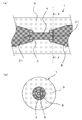
- (A) is the principal part expanded longitudinal sectional view which shows an example of embodiment of the heater of this invention
- (b) is a cross-sectional view in the XX line shown to (a).
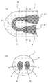
- (A) is a principal part expanded longitudinal sectional view which shows the other example of embodiment of the heater of this invention
- (b) is a cross-sectional view in the XX line shown to (a).
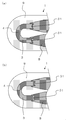
- (A) is a principal part expanded longitudinal sectional view which shows the other example of embodiment of the heater of this invention
- (b) is a cross-sectional view in the XX line shown to (a).
- (A) is a principal part expanded longitudinal sectional view which shows the other example of embodiment of the heater of this invention
- (b) is a cross-sectional view in the XX line shown to (a).
- (A), (b) is the principal part expansion longitudinal cross-sectional view which shows the other example of embodiment of the heater of this invention, respectively.
- It is a schematic longitudinal cross-sectional view which shows an example of embodiment of the glow plug of this invention.
- FIG. 1 (a) is a longitudinal sectional view showing an example of an embodiment of the heater of the present invention
- FIG. 1 (b) is a transverse sectional view taken along line XX shown in FIG. 1 (a).
- 2A is a longitudinal sectional view showing another example of the embodiment of the heater of the present invention
- FIG. 2B is a transverse sectional view taken along the line XX shown in FIG. 2A. is there.
- the heater 1 includes an insulating base 9, a resistor 3 embedded in the insulating base 9, and an insulating base 9 embedded in the insulating base 9, connected to the resistor 3 on the front end side, and insulated on the rear end side. 9 and a lead 8 led out to the surface of the resistor 9, and the lead 8 is thicker than the resistor 3, and is connected so that the end of the resistor 3 enters the tip of the lead 8, A concave portion 31 is provided on the end surface of the resistor 3, and a part of the lead 8 enters the concave portion 31.
- the insulating base 9 in the heater 1 of the present embodiment is formed in a rod shape, for example.
- the insulating substrate 9 covers the resistor 3 and the lead 8.
- the resistor 3 and the lead 8 are embedded in the insulating substrate 9.
- the insulating base 9 is made of ceramics, which can withstand temperatures higher than that of metal, so that it is possible to provide the heater 1 with improved reliability at the time of rapid temperature rise. become.
- ceramics having electrical insulation properties such as oxide ceramics, nitride ceramics, carbide ceramics can be used.
- the insulating substrate 9 is preferably made of silicon nitride ceramics.
- silicon nitride ceramics is superior in terms of high strength, high toughness, high insulation, and heat resistance because silicon nitride, which is a main component, is used.
- This silicon nitride ceramic is, for example, 3 to 12% by mass of a rare earth element oxide such as Y 2 O 3 , Yb 2 O 3 , Er 2 O 3 as a sintering aid with respect to silicon nitride as a main component, 0.5 to 3% by mass of Al 2 O 3 and further SiO 2 are mixed so that the amount of SiO 2 contained in the sintered body is 1.5 to 5% by mass, and molded into a predetermined shape, and thereafter 1650 to 1780 ° C. Can be obtained by hot press firing.
- the coefficient of thermal expansion of the silicon nitride ceramic that is the base material can be brought close to the coefficient of thermal expansion of the resistor 3, and the durability of the heater 1 can be improved.
- the region between the leads 8 can be used as the heat generating portion 4.
- a spiral region may be provided.
- the region between the leads 8 of the resistor 3 can be the heat generating portion 4, and the vicinity of the middle point of the folding is the heat generating portion 4 that generates the most heat.
- carbonized_material, nitride, silicide, etc., such as W, Mo, Ti, etc. as a main component can be used.
- tungsten carbide is one of the above materials because it has a small difference in thermal expansion coefficient from the insulating base 9, high heat resistance, and low specific resistance. It is excellent as a material for the resistor 3.
- the resistor 3 is preferably composed mainly of WC of an inorganic conductor, and the content of silicon nitride added thereto is 20% by mass or more.
- the conductor component serving as the resistor 3 has a higher coefficient of thermal expansion than silicon nitride, and thus is usually in a state where tensile stress is applied.
- the thermal expansion coefficient of the resistor 3 is brought close to the thermal expansion coefficient of the insulating base 9, and the thermal expansion coefficient when the heater 1 is heated and lowered. The stress due to the difference can be relaxed.
- the content of silicon nitride contained in the resistor 3 is 40% by mass or less, the resistance value of the resistor 3 can be made relatively small and stabilized. Therefore, the content of silicon nitride contained in the resistor 3 is preferably 20% by mass to 40% by mass. More preferably, the silicon nitride content is 25% by mass to 35% by mass. Further, as a similar additive to the resistor 3, boron nitride can be added in an amount of 4% by mass to 12% by mass instead of silicon nitride.
- the thickness of the resistor 3 (the vertical thickness shown in FIG. 2B) is preferably 0.5 mm to 1.5 mm, and the width of the resistor 3 (the horizontal width shown in FIG. 2B) is 0.3 mm. ⁇ 1.3mm is good. By setting it within this range, the resistance value of the resistor 3 can be reduced to sufficiently generate heat.
- the insulating base 9 has a laminated structure formed by laminating, for example, halved molded bodies, the adhesion at the laminated interface of the insulating base 9 having a laminated structure can be maintained.
- the lead 8 joined to the end of the resistor 3 can be composed mainly of carbides such as W, Mo, Ti, nitrides, silicides, and the like.
- the resistance value per unit length is lower than that of the resistor 3, such as including more than the resistor 3 or having a larger cross-sectional area than the resistor 3.
- the lead 8 can be formed using the same material as the resistor 3.
- WC is suitable as a material for the lead 8 in that the difference in coefficient of thermal expansion from the insulating base 9 is small, the heat resistance is high, and the specific resistance is small.
- the lead 8 is preferably composed mainly of WC, which is an inorganic conductor, and silicon nitride is added to the lead 8 so that the content is 15% by mass or more. As the silicon nitride content increases, the thermal expansion coefficient of the lead 8 can be made closer to the thermal expansion coefficient of the insulating substrate 9.
- the silicon nitride content is preferably 15% by mass to 40% by mass. More preferably, the silicon nitride content is 20% by mass to 35% by mass.
- the lead 8 has a lower resistance value per unit length. It may be.
- the lead 8 is thicker than the resistor 3, and is connected so that the end of the resistor 3 enters the tip of the lead 8, A concave portion 31 is provided on the end surface of the resistor 3, and a part of the lead 8 enters the concave portion 31. That is, at the junction between the resistor 3 and the lead 8, the end of the resistor 3 first enters the tip of the lead 8, and the recess 31 provided on the end surface of the resistor 3 enters the tip of the lead 8. A part of the lead 8 is inserted.
- the term “joint portion” as used herein refers to a region where the interface between the resistor 3 and the lead 8 exists when viewed in a cross section parallel to the axial direction of the lead 8.
- the end of the resistor 3 preferably enters, for example, 0.1 to 1.0 mm into the tip of the lead 8, and the depth of the recess 31 provided on the end of the resistor 3 is the tip of the lead 8 at the end of the resistor 3.
- it is 0.01 to 0.3 mm, although it varies depending on the amount entering the portion.
- the shape of the recess 31 include circular, elliptical, and polygonal cross-sectional shapes (opening shapes).
- the diameter is, for example, 0.05 to 1.3 mm. preferable.
- the inside of the recess 31 has the composition of the lead 8 having a lower resistance than the resistor 3, the heat generation load is reduced and the stress can be reduced.
- the concave portion 31 of the resistor 3 in the joint portion is provided in the central portion of the end face of the resistor 3.
- the heater 1 shown in FIG. 3 has a shape in which the end portion of the resistor 3 enters the substantially central portion of the cross section of the tip portion of the lead 8, and the heater 1 shown in FIG.
- the shape shown in FIG. 4 is more preferable because it enters the inner side of the cross section of the tip of the lead 8 and has a long distance from the resistor 3 to the surface of the heater 1 and is excellent in insulation during use.
- the inner surface of the concave portion 31 of the resistor 3 in the joint portion has no corner portion. Since the inner surface of the recess 31 does not have an acute corner, that is, the inner surface is a quadratic curved surface, no stress is concentrated on the recess 31 and no crack is generated. As a result, the product resistance does not change even with long-term use. Therefore, the reliability and durability of the heater 1 are further improved.
- the heater 1 shown in FIG. 5A has a shape in which a recess 31 is provided over almost the entire end surface of the resistor 3, and the heater 1 shown in FIG. Although the concave portion 31 is provided almost only in the vicinity of the central portion, the shape shown in FIG. 5A is preferable in that the heat generation load is further reduced and the stress can be effectively reduced.
- the concave portion 31 of the resistor 3 in the joint portion is provided on both end faces of the resistor 3.
- the heater 1 shown in FIGS. 1 to 5 has a shape in which the end of the resistor 3 is encircled by the tip of the lead 8.
- the end of the resistor 3 is not necessarily required.
- the end of the resistor 3 is preferably surrounded by the tip of the lead 8, although the portion may not be surrounded by the tip of the lead 8, for example, a part or a plurality of portions may be cut out. It is good to get in.
- the lead 8 covering the thermally expanding resistor 3 serves as a buffer material with insulating ceramics having different linear expansion coefficients, and cracks are not generated by reducing stress concentration.
- the product resistance does not change even with long-term use. Therefore, the reliability and durability of the heater 1 can be further improved.
- the heater 1 of the present embodiment is used as a glow plug including the heater 1 and a metal holding member 7 that is electrically connected to the lead 8 and holds the heater 1.
- the metal holding member 7 is a cylindrical body that holds the heater 1, and is joined to one lead 8 drawn to the side surface of the ceramic base 9 with a brazing material or the like.
- the heater 1 of the present embodiment can be formed by, for example, an injection molding method using a die having the shape of the resistor 3, the lead 8, and the insulating base 9.
- a conductive paste to be the resistor 3 and the lead 8 including the conductive ceramic powder and the resin binder is manufactured, and a ceramic paste to be the insulating base 9 including the insulating ceramic powder and the resin binder is manufactured.
- a conductive paste molded body (molded body A) having a predetermined pattern to be the resistor 3 is formed by an injection molding method or the like using the conductive paste.
- the conductive paste is filled into the mold to form a conductive paste molded body (molded body B) having a predetermined pattern to be the leads 8.
- the molded object A and the molded object B connected to it will be in the state hold
- the obtained molded body D is fired at, for example, a temperature of 1650 ° C. to 1800 ° C. and a pressure of 30 MPa to 50 MPa, whereby the heater 1 can be manufactured.
- the firing is preferably performed in a non-oxidizing gas atmosphere such as hydrogen gas.
- the heater of the example of the present invention was manufactured as follows.
- a conductive paste containing 50% by mass of tungsten carbide (WC) powder, 35% by mass of silicon nitride (Si 3 N 4 ) powder, and 15% by mass of a resin binder is injection-molded into a mold to form a resistor.
- a formed product A was produced.
- the mold is filled with the conductive paste to be the lead, thereby forming the molded body B to be connected to the molded body A. did.
- joints between the resistor and the lead were formed using molds having various shapes.
- the obtained molded body D was put into a cylindrical carbon mold, and then hot-pressed and sintered in a non-oxidizing gas atmosphere made of nitrogen gas at 1700 ° C. and a pressure of 35 MPa.
- a bracket holding member was brazed to the end of the lead exposed on the surface of the obtained sintered body to produce a heater.
- the resistor 3 has a vertical thickness of 0.9 mm and a horizontal width of 0.6 mm, and the end of the resistor 3 is inserted into the tip of the lead 8 by 0.5 mm, and is provided on the end surface of the resistor 3.
- a heater having a recess 31 depth of 0.05 mm and a recess 31 diameter of 0.5 mm was produced.
- the resistor 3 has a vertical thickness of 0.9 mm and a horizontal width of 0.6 mm, and the end of the resistor 3 does not enter the tip of the lead 8. A heater having no recess 31 was produced.
- a cold cycle test was conducted using these heaters.
- the conditions of the thermal cycle test are as follows: First, energize the heater and set the applied voltage so that the temperature of the resistor is 1400 ° C. 1) Energize for 5 minutes, 2) Deenergize for 2 minutes 1), 2) The cycle was 10,000 cycles.
- the resistance change of the sample of the example of the present invention was 1% or less. Further, there was no trace of local heat generation at the connection portion between the resistor and the lead of this sample, and no microcracks were observed. On the other hand, the resistance change of the sample of the comparative example was 5% or more, and microcracks were confirmed.
- Heater 3 Resistor 31: Concave part 4: Heat generating part 7: Metal holding member 8: Lead 9: Insulating substrate
Landscapes
- Engineering & Computer Science (AREA)
- Chemical & Material Sciences (AREA)
- Combustion & Propulsion (AREA)
- Mechanical Engineering (AREA)
- General Engineering & Computer Science (AREA)
- Ceramic Engineering (AREA)
- Resistance Heating (AREA)
Abstract
Description
3:抵抗体
31:凹部
4:発熱部
7:金属製保持部材
8:リード
9:絶縁基体
Claims (6)
- 絶縁基体と、
該絶縁基体に埋設された抵抗体と、
前記絶縁基体に埋設され、先端側で前記抵抗体に接続されるとともに後端側で前記絶縁基体の表面に導出されたリードとを備え、
該リードは前記抵抗体よりも太い形状であって、前記リードの先端部に前記抵抗体の端部が入り込むようにして接続されているとともに、前記抵抗体の端面には凹部が設けられ、該凹部に前記リードの一部が入り込んでいることを特徴とするヒータ。 - 前記凹部が前記抵抗体の端面の中央部に設けられていることを特徴とする請求項1に記載のヒータ。
- 前記凹部の内面は角部がないことを特徴とする請求項1または請求項2に記載のヒータ。
- 前記凹部が前記抵抗体の両方の端面に設けられていることを特徴とする請求項1乃至請求項3のうちいずれかに記載のヒータ。
- 前記抵抗体の端部が前記リードの先端部に取り囲まれるように入り込んでいることを特徴とする請求項1乃至請求項4のうちいずれかに記載のヒータ。
- 請求項1に記載のヒータと、前記リードと電気的に接続されて前記ヒータを保持する金属製保持部材とを備えたことを特徴とするグロープラグ。
Priority Applications (5)
| Application Number | Priority Date | Filing Date | Title |
|---|---|---|---|
| US14/114,063 US20140053795A1 (en) | 2011-04-27 | 2012-04-27 | Heater and glow plug provided with same |
| JP2013512466A JP5766282B2 (ja) | 2011-04-27 | 2012-04-27 | ヒータおよびこれを備えたグロープラグ |
| EP12776164.1A EP2704518B1 (en) | 2011-04-27 | 2012-04-27 | Heater and glow plug provided with same |
| CN201280020674.7A CN103493585B (zh) | 2011-04-27 | 2012-04-27 | 加热器以及具有该加热器的电热塞 |
| KR1020137026554A KR101504631B1 (ko) | 2011-04-27 | 2012-04-27 | 히터 및 이것을 구비한 글로우 플러그 |
Applications Claiming Priority (2)
| Application Number | Priority Date | Filing Date | Title |
|---|---|---|---|
| JP2011099601 | 2011-04-27 | ||
| JP2011-099601 | 2011-04-27 |
Publications (1)
| Publication Number | Publication Date |
|---|---|
| WO2012147919A1 true WO2012147919A1 (ja) | 2012-11-01 |
Family
ID=47072431
Family Applications (1)
| Application Number | Title | Priority Date | Filing Date |
|---|---|---|---|
| PCT/JP2012/061373 Ceased WO2012147919A1 (ja) | 2011-04-27 | 2012-04-27 | ヒータおよびこれを備えたグロープラグ |
Country Status (6)
| Country | Link |
|---|---|
| US (1) | US20140053795A1 (ja) |
| EP (1) | EP2704518B1 (ja) |
| JP (1) | JP5766282B2 (ja) |
| KR (1) | KR101504631B1 (ja) |
| CN (1) | CN103493585B (ja) |
| WO (1) | WO2012147919A1 (ja) |
Families Citing this family (4)
| Publication number | Priority date | Publication date | Assignee | Title |
|---|---|---|---|---|
| US9491805B2 (en) * | 2011-04-27 | 2016-11-08 | Kyocera Corporation | Heater and glow plug provided with same |
| DE102015222072B4 (de) * | 2015-11-10 | 2019-03-28 | Robert Bosch Gmbh | Heizvorrichtung für MEMS-Sensor |
| JP6592103B2 (ja) * | 2015-11-27 | 2019-10-16 | 京セラ株式会社 | ヒータおよびこれを備えたグロープラグ |
| JP7025258B2 (ja) * | 2018-03-20 | 2022-02-24 | 京セラ株式会社 | ヒータ |
Citations (3)
| Publication number | Priority date | Publication date | Assignee | Title |
|---|---|---|---|---|
| JPH03149791A (ja) * | 1989-11-04 | 1991-06-26 | Ngk Spark Plug Co Ltd | セラミックヒータ |
| JP2000130754A (ja) * | 1998-10-26 | 2000-05-12 | Ngk Spark Plug Co Ltd | セラミックグロープラグ |
| JP2010210134A (ja) * | 2009-03-10 | 2010-09-24 | Ngk Spark Plug Co Ltd | セラミックヒータ及びグロープラグ |
Family Cites Families (4)
| Publication number | Priority date | Publication date | Assignee | Title |
|---|---|---|---|---|
| JP3269253B2 (ja) * | 1994-04-04 | 2002-03-25 | 株式会社デンソー | セラミックヒータ |
| JP3411498B2 (ja) * | 1997-04-23 | 2003-06-03 | 日本特殊陶業株式会社 | セラミックヒータ、その製造方法、及びセラミックグロープラグ |
| JP3924193B2 (ja) * | 2001-05-02 | 2007-06-06 | 日本特殊陶業株式会社 | セラミックヒータ、それを用いたグロープラグ及びセラミックヒータの製造方法 |
| KR101441595B1 (ko) * | 2007-02-22 | 2014-09-19 | 쿄세라 코포레이션 | 세라믹 히터, 이 세라믹 히터를 이용한 글로 플러그 및 세라믹 히터의 제조 방법 |
-
2012
- 2012-04-27 WO PCT/JP2012/061373 patent/WO2012147919A1/ja not_active Ceased
- 2012-04-27 KR KR1020137026554A patent/KR101504631B1/ko active Active
- 2012-04-27 US US14/114,063 patent/US20140053795A1/en not_active Abandoned
- 2012-04-27 EP EP12776164.1A patent/EP2704518B1/en active Active
- 2012-04-27 CN CN201280020674.7A patent/CN103493585B/zh active Active
- 2012-04-27 JP JP2013512466A patent/JP5766282B2/ja active Active
Patent Citations (3)
| Publication number | Priority date | Publication date | Assignee | Title |
|---|---|---|---|---|
| JPH03149791A (ja) * | 1989-11-04 | 1991-06-26 | Ngk Spark Plug Co Ltd | セラミックヒータ |
| JP2000130754A (ja) * | 1998-10-26 | 2000-05-12 | Ngk Spark Plug Co Ltd | セラミックグロープラグ |
| JP2010210134A (ja) * | 2009-03-10 | 2010-09-24 | Ngk Spark Plug Co Ltd | セラミックヒータ及びグロープラグ |
Also Published As
| Publication number | Publication date |
|---|---|
| EP2704518A1 (en) | 2014-03-05 |
| JPWO2012147919A1 (ja) | 2014-07-28 |
| CN103493585B (zh) | 2016-03-02 |
| JP5766282B2 (ja) | 2015-08-19 |
| KR101504631B1 (ko) | 2015-03-20 |
| US20140053795A1 (en) | 2014-02-27 |
| CN103493585A (zh) | 2014-01-01 |
| EP2704518B1 (en) | 2017-10-18 |
| KR20130137675A (ko) | 2013-12-17 |
| EP2704518A4 (en) | 2014-10-22 |
Similar Documents
| Publication | Publication Date | Title |
|---|---|---|
| JP5166451B2 (ja) | セラミックヒータおよびグロープラグ | |
| JP5436675B2 (ja) | ヒータおよびこれを備えたグロープラグ | |
| JP6139629B2 (ja) | ヒータおよびこれを備えたグロープラグ | |
| JP5766282B2 (ja) | ヒータおよびこれを備えたグロープラグ | |
| JP5289462B2 (ja) | セラミックヒータ | |
| JP2016184592A (ja) | ヒータおよびこれを備えたグロープラグ | |
| JP5436687B2 (ja) | ヒータおよびこれを備えたグロープラグ | |
| JP5726311B2 (ja) | ヒータおよびこれを備えたグロープラグ | |
| JP5829691B2 (ja) | ヒータおよびこれを備えたグロープラグ |
Legal Events
| Date | Code | Title | Description |
|---|---|---|---|
| 121 | Ep: the epo has been informed by wipo that ep was designated in this application |
Ref document number: 12776164 Country of ref document: EP Kind code of ref document: A1 |
|
| ENP | Entry into the national phase |
Ref document number: 20137026554 Country of ref document: KR Kind code of ref document: A |
|
| ENP | Entry into the national phase |
Ref document number: 2013512466 Country of ref document: JP Kind code of ref document: A |
|
| WWE | Wipo information: entry into national phase |
Ref document number: 14114063 Country of ref document: US |
|
| NENP | Non-entry into the national phase |
Ref country code: DE |
|
| REEP | Request for entry into the european phase |
Ref document number: 2012776164 Country of ref document: EP |