WO2012157146A1 - Générateur de flux en vortex - Google Patents
Générateur de flux en vortex Download PDFInfo
- Publication number
- WO2012157146A1 WO2012157146A1 PCT/JP2011/080297 JP2011080297W WO2012157146A1 WO 2012157146 A1 WO2012157146 A1 WO 2012157146A1 JP 2011080297 W JP2011080297 W JP 2011080297W WO 2012157146 A1 WO2012157146 A1 WO 2012157146A1
- Authority
- WO
- WIPO (PCT)
- Prior art keywords
- air
- flow generator
- blade
- swirling flow
- swirling
- Prior art date
- Legal status (The legal status is an assumption and is not a legal conclusion. Google has not performed a legal analysis and makes no representation as to the accuracy of the status listed.)
- Ceased
Links
Images




Classifications
-
- B—PERFORMING OPERATIONS; TRANSPORTING
- B04—CENTRIFUGAL APPARATUS OR MACHINES FOR CARRYING-OUT PHYSICAL OR CHEMICAL PROCESSES
- B04C—APPARATUS USING FREE VORTEX FLOW, e.g. CYCLONES
- B04C5/00—Apparatus in which the axial direction of the vortex is reversed
- B04C5/08—Vortex chamber constructions
- B04C5/103—Bodies or members, e.g. bulkheads, guides, in the vortex chamber
-
- B—PERFORMING OPERATIONS; TRANSPORTING
- B01—PHYSICAL OR CHEMICAL PROCESSES OR APPARATUS IN GENERAL
- B01D—SEPARATION
- B01D45/00—Separating dispersed particles from gases or vapours by gravity, inertia, or centrifugal forces
- B01D45/12—Separating dispersed particles from gases or vapours by gravity, inertia, or centrifugal forces by centrifugal forces
-
- B—PERFORMING OPERATIONS; TRANSPORTING
- B04—CENTRIFUGAL APPARATUS OR MACHINES FOR CARRYING-OUT PHYSICAL OR CHEMICAL PROCESSES
- B04C—APPARATUS USING FREE VORTEX FLOW, e.g. CYCLONES
- B04C5/00—Apparatus in which the axial direction of the vortex is reversed
- B04C5/02—Construction of inlets by which the vortex flow is generated, e.g. tangential admission, the fluid flow being forced to follow a downward path by spirally wound bulkheads, or with slightly downwardly-directed tangential admission
- B04C5/06—Axial inlets
-
- B—PERFORMING OPERATIONS; TRANSPORTING
- B04—CENTRIFUGAL APPARATUS OR MACHINES FOR CARRYING-OUT PHYSICAL OR CHEMICAL PROCESSES
- B04C—APPARATUS USING FREE VORTEX FLOW, e.g. CYCLONES
- B04C5/00—Apparatus in which the axial direction of the vortex is reversed
- B04C5/08—Vortex chamber constructions
-
- F—MECHANICAL ENGINEERING; LIGHTING; HEATING; WEAPONS; BLASTING
- F04—POSITIVE - DISPLACEMENT MACHINES FOR LIQUIDS; PUMPS FOR LIQUIDS OR ELASTIC FLUIDS
- F04B—POSITIVE-DISPLACEMENT MACHINES FOR LIQUIDS; PUMPS
- F04B39/00—Component parts, details, or accessories, of pumps or pumping systems specially adapted for elastic fluids, not otherwise provided for in, or of interest apart from, groups F04B25/00 - F04B37/00
- F04B39/16—Filtration; Moisture separation
Definitions
- the present invention relates to a swirling flow generator that swirls air containing foreign matter such as droplets and dust to remove foreign matter from the air.
- Patent Document 1 describes a vacuum cleaner in which air containing dust sucked from a suction port is swirled by a swivel unit.
- Patent Document 2 describes a filter in which a liquid is swirled in order to remove foreign matters mixed in a coolant liquid.
- An object of the present invention is to make it possible to separate and remove foreign substances in the air without increasing the inner diameter of the swirl flow generation chamber.
- the swirling flow generator of the present invention is a swirling flow generator that purifies air by removing foreign matters such as droplets and dust contained in the air, and the inner periphery of the swirling flow generating chamber in which air flows in the axial direction.
- a plurality of blades extending in the axial direction along the surface and inclined in the circumferential direction are formed in a cylindrical shape, and swirled by ejecting the air flowing in the axial direction along the blades radially inward. It has a blade cylinder part which forms a flow, and an annular base part arranged at the lower end of the blade cylinder part.
- the swirling flow generator of the present invention forms a droplet guide surface inclined downward inward in the radial direction on the upper surface of the annular base portion, and drops attached to the upper surface of the annular base portion are disposed on the droplet guide surface. It is dripped downward by this.
- the swirling flow generator of the present invention is characterized in that it has a closed lid portion that is disposed at the upper end of the blade cylindrical portion and guides the air flowing into the swirling flow generating chamber toward the blade.
- the swirling flow generator according to the present invention is characterized in that a liquid discharge groove for guiding the liquid downward is formed on the outer peripheral surface of the annular base portion.
- the swirling flow generator of the present invention is characterized in that the annular base portion and the blade cylinder portion are integrally formed.
- the swirl flow generator according to the present invention is characterized in that a discharge pipe for discharging the cleaned air to the outside is provided inside the blade cylinder part.
- the blade cylinder portion is formed by arranging a plurality of blades extending in the axial direction along the inner peripheral surface of the swirl flow generation chamber in a cylindrical shape, the radial thickness of the blade cylinder portion Despite its thin dimensions, it is possible to efficiently generate a swirling flow at a low pressure. Thereby, the foreign matter in the air can be separated and removed without increasing the inner diameter of the swirl flow generating chamber.
- FIG. 2 is a cross-sectional view taken along line AA in FIG.
- FIG. 3 is a sectional view taken along line BB in FIG.
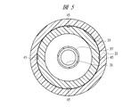
- FIG. 2 is a sectional view taken along line CC in FIG. 1.
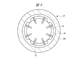
- FIG. 2 is a sectional view taken along line DD in FIG.
- the filter 10 has a metal port block 13 in which a primary side port 11 and a secondary side port 12 are formed.
- the primary side port 11 is connected to a primary side pneumatic line made of piping or the like (not shown). Air from the air pressure source is supplied to the primary side port 11 by this pneumatic line.
- the secondary side port 12 is connected to a secondary side pneumatic line made of piping (not shown), and the air that has been cleaned by removing liquid droplets or the like is Supplied from the side port to external pneumatic equipment.
- the primary side port 11 and the secondary side port 12 are opened coaxially on the opposite side surface of the port block 13.
- the side surface of the port block 13 in which each port is opened is substantially flat, and the port block 13 has a generally cubic shape as shown in FIG.
- An accommodation hole 14 is formed in the port block 13, and the primary side port 11 communicates with the accommodation hole 14.
- a support portion 16 in which a communication hole 15 is formed is provided at the center of the port block 13, and the air supplied to the primary side port 11 through a communication space between the support portion 16 and the accommodation hole 14. Will flow toward the lower part of the accommodation hole 14.
- a cylindrical male screw portion 17 is provided at the lower end portion of the port block 13.
- a resin-made separation cylinder 20 is detachably attached to the male screw portion 17, and a female screw portion 18 that is screwed to the male screw portion 17 is provided at an upper end portion of the separation cylinder 20.
- the separation cylinder 20 has a cylindrical portion 21 having a constant inner diameter, and a conical portion 22 that continues downward from the cylindrical portion 21 and decreases toward the lower end.
- a separation unit 23 is formed by the port block 13 and the separation cylinder 20 attached thereto.
- An upper swirl flow generation chamber 24 and a lower separation chamber 25 communicating with the upper swirl flow generation chamber 24 are formed inside the separation unit 23.
- the swirl flow generation chamber 24 is formed by the port block 13 and the separation cylinder 20, but the swirl flow generation chamber 24 is formed by the port block 13 and separated by the separation cylinder 20.
- the chamber 25 may be formed, and the swirl flow generation chamber 24 and the separation chamber 25 may be formed in the separation cylinder 20.
- the male screw part 26 is provided in the conical part 22 of the separation cylinder 20, and the outer diameter of the male screw part 26 is the same as the outer diameter of the male screw part 17 of the port block 13.
- a collection container 27 is detachably attached to the male screw portion 26.
- the collection container 27 has a cylindrical portion 28a and a bottom wall portion 28b integrated with the cylindrical portion 28a, and is formed of a transparent material.
- a female screw portion 29 that is screwed to the male screw portion 26 is provided at the upper end portion of the collection container 27.
- the internal diameter of the internal thread portion 29 is the same as the internal diameter of the internal thread portion 18 of the cylindrical portion 21 of the separation cylinder 20.
- the inside of the collection container 27 is a storage chamber 30 for storing foreign substances such as liquid, and the interior of the separation cylinder 20 and the storage chamber 30 are communicated with each other by a discharge port 31 formed at the lower end of the separation cylinder 20. Yes.
- a swirl flow generator 32 made of resin is mounted in the swirl flow generation chamber 24 of the separation unit 23.
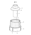
- the swirling flow generator 32 has an annular base portion 33 fitted to the inner peripheral surface of the cylindrical portion 21 of the separation cylinder 20.
- a blade cylinder portion 34 is integrated with the annular base portion 33.
- the blade cylindrical portion 34 has a plurality of blades or blades 35 extending in the axial direction along the inner peripheral surface of the accommodation hole 14, that is, the inner peripheral surface of the swirling flow generating chamber 24.
- the blades 35 are arranged in a cylindrical shape with a gap 36 therebetween. As shown in FIG. 4, each blade 35 has an angle of inclination with respect to a tangent to the inner peripheral surface of the blade cylindrical portion 34.
- the blade cylinder part 34 is composed of 21 blades 35. As shown in FIG. 4, each blade 35 is set such that the thickness at the radially inner portion is thinner than the thickness at the radially outer portion, and the gap 36 formed between each blade is separated. While extending in the axial direction along the central axis of the unit 23, the unit 23 is inclined in the circumferential direction.
- a discharge pipe 37 is attached to the communication hole 15, and the lower end surface of the discharge pipe 37 extends downward from the blade cylinder portion 34 to be a position of the annular base portion 33. Air that has been cleaned by removing foreign substances is guided to the secondary port 12 by the discharge pipe 37.
- the discharge pipe 37 is integrally formed with a discharge lid 37 and a closing lid portion 38 disposed at the upper end of the blade cylinder portion 34. The closing lid portion 38 prevents air that has flowed into the accommodation hole 14 from the primary port 11 from flowing into the blade cylinder portion 34 from the inside in the radial direction of the blade cylinder portion 34.
- the swirl flow generator 32 is fitted to the inner peripheral surface of the cylindrical portion 21 of the separation cylindrical body 20 that is disposed at the lower end portion of the blade cylindrical portion 34 that has an overall cylindrical shape.
- the annular base portion 33, the blade cylinder portion 34, and the closing lid portion 38 disposed at the upper end portion of the discharge pipe 37 are formed. Accordingly, the air supplied from the primary port 11 into the accommodation hole 14 flows axially into the swirl flow generation chamber 24 and flows into the gap 36 between the blades 35 from the upper outer peripheral surface of the blade cylindrical portion 34. To do.
- the air that has flowed into the gaps 36 is guided by the blades 35 and is ejected toward the blade cylindrical portion 34 while being inclined with respect to the tangential direction.
- the blade cylinder portion 34 formed by arranging the blades 35 in a cylindrical shape is integrated with the annular base portion 33, and the closing lid portion 38 integrated with the discharge pipe 37 is replaced with the blade cylinder body.
- the blade cylinder portion 34 and the closing lid portion 38 are integrally formed so that the annular base portion 33 abuts against the lower end surface of the blade cylinder portion 34. Also good. Further, although the discharge pipe 37 and the closing lid portion 38 are integrated, these may be separate members.
- the air that flows into the swirling flow generation chamber 24 from the primary side port 11 flows into the swirling flow generator 32 in the axial direction from the outer peripheral portion of the swirling flow generation chamber 24, and is The directional flow is converted into a swirl flow. Since the 21 blades 35 are arranged over the entire circumference of 360 degrees, the inflowing air is given a turning force over the entire circumference of 360 degrees. Accordingly, as compared with the case where air is supplied from the air supply port in the tangential direction to the inner peripheral surface of the separation cylinder 20 as in Patent Document 2, the separation cylinder 20 is efficiently increased in speed without increasing the inner diameter. The swirl flow can be generated. Therefore, it is possible to reduce the size of the filter for forming the swirl flow and removing the droplets contained therein.
- the separation cylinder 20 has a cylindrical portion 21 and a conical portion 22 below the cylindrical portion 21, and the swirling flow generated by the swirling flow generator 32 can prevent the centrifugal force from being attenuated in the conical portion 22. Therefore, if the lower part of the separation cylinder 20 has a conical shape, the separation efficiency of the foreign matters by attaching foreign matters such as droplets to the inner peripheral surface can be increased.
- the air that has been cleaned by removing foreign substances rises while swirling, flows into the discharge pipe 37, and flows out from the secondary port 12.
- a notch 39 is formed on the radially inner side of the upper end of the blade cylinder 34.
- the inner diameter of the cutout portion 39 corresponds to the outer diameter R of the lower end portion of the closing lid portion 38, and the closing lid portion 38 is fitted into the cutout portion 39.
- a taper surface 41 is formed such that a portion of the outer peripheral surface of the closing lid portion 38 above the upper end surface of the blade cylinder portion 34 to the support portion 16 has a smaller diameter upward.
- the air that has flowed into the swirl flow generation chamber 24 from the primary port 11 is guided radially outward by the tapered surface 41, and the respective blades 35 from the gaps 36 between the closing lid portion 38 and the accommodation hole 14. , Along the inner peripheral surface of the blade cylinder portion 34, flows into a swirling flow.
- the lower surface 42 of the closing lid portion 38 is a flat surface that is perpendicular to the central axis of the closing lid portion 38 and extends from the outer peripheral portion toward the inner peripheral portion so that droplets contained in the swirling flow do not adhere to the lower surface 42. It has become. As a result, the liquid droplets that have flowed into the blade cylinder portion 34 together with air from the outer periphery of the closing lid portion 38 flow downward along with the swirl flow without being attached to the lower surface 42. According to an experiment, when the lower surface 42 was inclined upward from the outside in the radial direction toward the inside, droplets adhered to the lower surface 42.
- a gap 43 is formed between the inner peripheral surface of the accommodation hole 14 and the outer peripheral surface of the blade cylinder part 34. Part of the liquid droplets mixed into the air from the primary side port 11 and flowing into the swirl flow generation chamber 24 is guided by the gap 43 between the blade 35 and the inner peripheral surface of the accommodation hole 14. It will flow to the lower end of 35.
- a droplet guide surface 44 that is inclined downward toward the outer side in the radial direction is formed on a portion of the upper surface of the annular base portion 33 outside the outer diameter of the blade cylinder portion 34. Yes. As shown in FIG.
- a plurality of liquid discharge grooves 45 are formed on the outer peripheral surface of the annular base portion 33, and the droplets that have flowed to the outermost peripheral portion of the droplet guide surface 44 are discharged into the respective liquids. Guided from the groove 45 to the lower part of the separation cylinder 20.
- a portion between the outer peripheral surface and the inner peripheral surface of the blade cylinder portion 34 is formed with a droplet guide surface 46 that is inclined downward as it goes inward in the radial direction. .
- the droplets that flow downward through the gap 36 between the blades 35 and reach the upper surface of the annular base 33 are dropped downward from the minimum diameter portion of the inclined droplet guide surface 46.
- the inclined droplet guide surface 46 prevents the droplet from collecting at the base end portion of the blade cylindrical portion, and ensures that the droplet flows downward.
- the droplets such as water droplets and oil droplets that flow into the swirl flow generation chamber 24 from the primary side port 11
- the droplets that flow between the outer peripheral surface of the blade cylindrical portion 34 and the accommodation hole 14. Is guided by the droplet guide surface 44 and guided from the liquid discharge groove 45 to the inner peripheral surface of the separation cylinder 20, so that it can be reliably prevented from entering the discharge pipe 37.
- the liquid discharge groove 45 may be formed on the inner peripheral surface of the cylindrical portion 21.
- the lower surface of the annular base portion 33 is a tapered surface 47 inclined downward so that the inner diameter increases from the smallest diameter portion of the droplet guide surface 46 toward the outer peripheral surface.
- the tapered surface 47 is spread downward so that the inner diameter increases with the lower surface of the annular base 33 facing downward, the air guided by the blade 35 and turned into a swirl flow is tapered. It is guided to the separation chamber 25 of the separation cylinder 20 while increasing the turning radius toward 47.
- the lower end surface of the discharge pipe 37 is at the same axial position as the annular base 33, and the radially outer side of the lower end of the discharge pipe 37 is the annular base 33, but the inner surface of the annular base 33 faces downward.
- the tapered surface 47 Since the tapered surface 47 has a large inner diameter, it is possible to reliably prevent the droplets adhering to the tapered surface 47 from being caught inside the discharge pipe 37. In particular, even when the amount of air flowing in from the primary port 11 suddenly increases, it is possible to prevent droplets from being caught in the discharge pipe 37.
- the droplet may be caught in the discharge pipe 37 and enter if the inner peripheral surface of the annular base 33 is straightened.
- the enlarged diameter portion formed in the annular base portion 33 is not limited to the tapered surface, and if the inner diameter is set larger than the inner diameter of the blade cylindrical portion 34, the liquid droplets are discharged even as the enlarged diameter portion having a straight inner diameter. It is possible to prevent the wire 37 from being caught in the tube 37.
- the air that flows into the separation chamber 25 from the taper surface 47 and swirls along the inner peripheral surface of the cylindrical portion 21 is guided to the inner peripheral surface of the conical portion 22 whose inner diameter decreases toward the lower end portion, that is, the conical surface 48.
- the air flowing along the conical surface 48 maintains the generated centrifugal force, and the droplets contained in the air adhere to the conical surface 48 of the conical portion 22 and flow toward the discharge port 31 at the lower end. It will be.
- the droplet guide surface 44 is formed on the radially outer portion of the upper surface of the annular base portion 33, and the droplet guide surface 46 is formed on the radially inner portion, thereby reaching the upper surface of the annular base portion 33.
- the dropped liquid can be surely dropped downward.
- a baffle plate 51 provided with a liquid guide surface 50 facing the discharge port 31 is disposed in the collection container 27 .
- the baffle plate 51 is opposed to the discharge port 31 through a gap of the baffle arrangement distance L, and the liquid droplets that have dropped from the discharge port 31 are collected on the bottom of the storage chamber 30, and the tornado of the swirl flow Due to the effect, it is prevented from flowing back into the separation chamber 25.
- the liquid guide surface 50 of the baffle plate 51 is provided with eight fins 52 that extend in the radial direction of the liquid guide surface 50 and protrude upward. Yes. In this way, the plurality of radial fins 52 prevent the air in the storage chamber 30 from swirling with the air swirling in the discharge port 31.
- the baffle plate 51 provided with the fins 52 prevents the liquid in the storage chamber 30 from being wound up and flowing out to the secondary port 12 due to the tornado effect resulting from the swirling of air in the storage chamber 30. Is done. Further, the air flow swirled downward along the conical surface 48 is reversed by the baffle plate 51 and moves upward toward the discharge pipe 37.
- a substrate 53 having a larger diameter than that of the baffle plate 51 is integrated under the baffle plate 51.
- a cross-shaped leg portion 54 is attached to the substrate 53 by a connecting portion 53a shown in FIG.
- the leg portion 54 also has four plate-like members radially from the center in the radial direction.
- the leg portion 54 extends near the inner peripheral surface of the collection container 27 and has a large gap between the two large-diameter plates 54 b having notch holes 54 a near the axis and the inner peripheral surface of the collection container 27. And two small-diameter plates 54c. This reliably prevents the air from swirling in the storage chamber 30.
- the connecting portion 55 provided at the lower portion of the leg portion 54 is incorporated in a discharge hole 56 formed in the bottom wall portion 28 b of the collection container 27, and a discharge pipe 57 inserted below the discharge hole 56 is provided. It is connected to the connecting part 55.
- the discharge pipe 57 is engaged with the cam portion of the operation knob 58 rotatably attached to the outer periphery of the discharge port 28c provided in the bottom wall portion 28b.
- the operation knob 58 is rotated, the discharge pipe 57 is rotated. Moves up and down.
- the sealing material 59a provided on the connecting portion 55 is separated from the bottom wall portion 28b. As a result, the liquid inside the storage chamber 30 is discharged to the outside through the discharge pipe 57.
- the inner diameter of the outlet 31 of the separation cylinder 20 is D and the cone angle of the conical portion 22 at the lower end of the separation cylinder 20 is ⁇
- the inner diameter D is 6.5 to 9 mm.
- the cone angle ⁇ is set in the range of 20 to 30 degrees.
- the surface angle of the liquid guide surface 50 of the baffle plate 51 is ⁇ and the baffle arrangement distance between the discharge port 31 and the liquid guide surface 50 is L, the surface angle ⁇ is 90 to 180 degrees, and the baffle arrangement distance L is The thickness was 5 to 15 mm. As a result, it is possible to reliably prevent the liquid droplets falling downward from the discharge port 31 from rising and flowing back into the separation chamber 25. If the baffle arrangement distance L is shorter than 5 mm, the droplets adhering to the liquid guide surface 50 of the baffle plate 51 may flow backward into the separation cylinder 20.
- the baffle arrangement distance L is larger than 15 mm
- the liquid droplets that have passed through the discharge port 31 accumulate on the liquid guide surface 50, and the liquid droplets accumulated due to a change in the flow rate rise and scatter due to the tornado effect. May flow backward into the separation cylinder 20.
- the surface angle ⁇ is set to the above-described angle range, it is possible to reliably prevent the liquid droplets from flowing backward from the baffle plate 51.
- the state where the separation cylinder 20 is fastened to the male thread portion 17 of the port block 13 is locked to the outside of the female thread portion 18 of the separation cylinder 20, and the separation cylinder 20 is connected to the port block 13.
- a resin-made annular lock member 63 is mounted so as to be movable in the axial direction in order to operate the unlocking when removing from the housing.
- the state where the recovery container 27 is fastened to the male thread part 26 of the separation cylinder 20 is locked outside the female thread part 29 of the recovery container 27 and unlocked when the recovery container 27 is removed from the separation cylinder 20.
- an annular lock member 64 made of resin is mounted so as to be movable in the axial direction.
- the respective annular lock members 63 and 64 have the same structure.
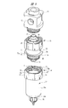
- FIG. 10 is an exploded perspective view of the recovery container 27 and the annular lock member 64.
- two convex guide portions 65 are provided that are shifted by 180 degrees in the circumferential direction.
- a concave guide portion 66 into which the convex guide portion 65 enters is formed on the inner peripheral surface of the annular lock member 64. Accordingly, the annular lock member 64 is guided by the convex guide portion 65 that enters the concave guide portion 66 and moves in the axial direction outside the collection container 27.
- the outer surface of the annular lock member 64 corresponding to the concave guide portion 66 is a protrusion 67 protruding outward in the radial direction in order to make the resin thickness uniform.
- the side wall 66a of the concave guide portion 66 comes into contact with the side surface 65a of the convex guide portion 65, and the rotation of the annular lock member 64 is prevented by both the guide portions 65 and 66.
- the outer surface of the annular lock member 64 corresponding to the concave guide portion 66 is a protrusion 67 protruding outward in the radial direction in order to make the resin thickness uniform.
- the concave guide portion 66 is provided with a stopper 68 against which the end portion 65b of the convex guide portion 65 abuts. The stopper 68 abuts against the end portion 65b of the guide portion 65, whereby the annular lock member 64 is recovered.
- the position of the container 27 in the direction toward the bottom wall portion 28b is restricted.
- the outer peripheral surface of the collection container 27 is provided with two inclined protrusions 71 shifted 90 degrees in the circumferential direction with respect to the protruding guide portion 65.
- the inclined protrusion 71 has an inclined surface 72 inclined outward in the radial direction toward the bottom of the collection container 27.
- a tongue piece 73 that is inclined inward in the radial direction and contacts the inclined surface 72 is provided so as to protrude inward of the annular lock member 64.
- a portion of the annular lock member 64 where the tongue piece 73 is provided has a concave shape, and an outer surface of the annular lock member 64 corresponding to the concave portion is a protrusion 74.
- the tongue piece 73 is integrally formed with the annular lock member 64 by a resin material that is elastically deformed, and is elastically deformed so that the tip end side is displaced in the radial direction.
- the tip of the tongue 73 that is, the inclined tip is inclined inward in the radial direction. Since the annular locking member 64 integrated with the tongue piece 73 is formed of an elastically deformable resin, the inclined tip of the tongue piece 73 can be elastically deformed by a radially outward force.
- the tip end side of the tongue piece 73 is elastically deformed so as to be displaced outward in the slip radial direction along the inclined surface 72.
- the annular locking member 64 Due to the repulsive force of the tongue 73 that is elastically deformed, the annular locking member 64 is biased with a pressing force in a direction toward the opening end of the collection container 27. Therefore, when the annular lock member 64 is manually moved to the unlocking position toward the bottom of the collection container 27 and the hand is released from the annular lock member 64, the annular lock member 64 is automatically caused by the pressing force. Will return to its original position. As described above, the inclined protrusion 71 having the inclined surface 72 and the tongue piece 73 form a pressing member that presses the annular lock member 64 toward the port block 13.
- the protruding portion 67 having the concave guide portion 66 provided on the inner surface protrudes outward in the axial direction from the end surface of the annular lock member 64 toward the port block 13, and the protruding end portion is connected to the movable side engaging portion 75. It has become.
- the flange 76 provided in the separation cylinder 20 is formed with a notch portion with which the movable side engaging portion 75 is engaged, and this notch portion serves as a fixed side engaging portion 77.
- the lower surface of the flange 76 is an abutting end surface 78 against which the annular lock member 64 is abutted, and a stopper surface 77 a is formed on the fixed-side engaging portion 77.
- the side surface of the movable side engaging portion 75 is a stopper surface 75a facing the stopper surface 77a.
- the annular lock member 63 has the same shape as the annular lock member 64, and a guide portion similar to the convex guide portion 65 shown in FIG. 10 is provided on the outer peripheral surface of the cylindrical portion 21 of the separation cylinder 20.
- an inclined protrusion 71 similar to the inclined protrusion 71 is provided.
- the annular lock member 63 is also provided with a movable side engaging portion similar to the movable side engaging portion 75 of the annular lock member 63, and this movable side engaging portion is a fixed side engaging portion provided in the port block 13. To be engaged.
- the swirl flow generator of the present invention is applied as a filter for removing foreign matters such as droplets and dust contained in compressed air. Therefore, the present invention can be applied to a centrifuge or a vacuum cleaner.
- This swirl generator is applied to filters, centrifuges, and vacuum cleaners in order to remove foreign substances contained in compressed air.
Landscapes
- Engineering & Computer Science (AREA)
- Chemical & Material Sciences (AREA)
- Chemical Kinetics & Catalysis (AREA)
- Mechanical Engineering (AREA)
- General Engineering & Computer Science (AREA)
- Physics & Mathematics (AREA)
- Fluid Mechanics (AREA)
- Cyclones (AREA)
- Separating Particles In Gases By Inertia (AREA)
- Filtering Of Dispersed Particles In Gases (AREA)
Abstract
Priority Applications (4)
| Application Number | Priority Date | Filing Date | Title |
|---|---|---|---|
| CN201180070934.7A CN103547375B (zh) | 2011-05-19 | 2011-12-27 | 回旋气流发生器 |
| DE112011105163.8T DE112011105163B4 (de) | 2011-05-19 | 2011-12-27 | Wirbelströmungserzeuger |
| US14/118,654 US8992648B2 (en) | 2011-05-19 | 2011-12-27 | Swirl flow generator |
| KR1020137030636A KR101911454B1 (ko) | 2011-05-19 | 2011-12-27 | 선회류 발생기 |
Applications Claiming Priority (2)
| Application Number | Priority Date | Filing Date | Title |
|---|---|---|---|
| JP2011-112765 | 2011-05-19 | ||
| JP2011112765A JP5666379B2 (ja) | 2011-05-19 | 2011-05-19 | 旋回流発生器 |
Publications (1)
| Publication Number | Publication Date |
|---|---|
| WO2012157146A1 true WO2012157146A1 (fr) | 2012-11-22 |
Family
ID=47176504
Family Applications (1)
| Application Number | Title | Priority Date | Filing Date |
|---|---|---|---|
| PCT/JP2011/080297 Ceased WO2012157146A1 (fr) | 2011-05-19 | 2011-12-27 | Générateur de flux en vortex |
Country Status (7)
| Country | Link |
|---|---|
| US (1) | US8992648B2 (fr) |
| JP (1) | JP5666379B2 (fr) |
| KR (1) | KR101911454B1 (fr) |
| CN (1) | CN103547375B (fr) |
| DE (1) | DE112011105163B4 (fr) |
| TW (1) | TWI523693B (fr) |
| WO (1) | WO2012157146A1 (fr) |
Families Citing this family (11)
| Publication number | Priority date | Publication date | Assignee | Title |
|---|---|---|---|---|
| JP5663394B2 (ja) * | 2011-05-06 | 2015-02-04 | 株式会社コガネイ | 調質機器の容器着脱装置 |
| CN104785050B (zh) * | 2014-01-16 | 2018-03-06 | 何玉佩 | 过滤模组 |
| JP6436827B2 (ja) | 2015-03-26 | 2018-12-12 | 株式会社コガネイ | エレメント組立体およびフィルタ |
| JP6370251B2 (ja) * | 2015-03-26 | 2018-08-08 | 株式会社コガネイ | エレメント組立体およびフィルタ |
| CN105148625B (zh) * | 2015-09-07 | 2017-03-22 | 中山乐满石油设备有限公司 | 一种涡流管式气液分离器 |
| CN105642077B (zh) * | 2016-02-29 | 2018-01-23 | 普利资环境科技(苏州)有限公司 | 一种用于高温污水处理的空气过滤器 |
| NO341434B1 (en) * | 2016-03-23 | 2017-11-13 | Stauper Offshore As | Hydrocarbon-water separator |
| US10843113B2 (en) | 2016-11-01 | 2020-11-24 | Ingersoll-Rand Industrial U.S., Inc. | Cyclonic oil separator for compressor oil reservoir |
| DE102020203516B3 (de) * | 2020-03-19 | 2021-07-29 | Eagleburgmann Germany Gmbh & Co. Kg | Zyklonabscheider |
| CN112254190A (zh) * | 2020-10-26 | 2021-01-22 | 佛山市顺德区美的洗涤电器制造有限公司 | 进风导流装置及组合灶 |
| WO2026028086A1 (fr) * | 2024-07-31 | 2026-02-05 | Covidien Lp | Séparateurs de fluide pour systèmes d'évacuation de panaches chirurgicaux |
Citations (5)
| Publication number | Priority date | Publication date | Assignee | Title |
|---|---|---|---|---|
| JPS546682U (fr) * | 1977-06-17 | 1979-01-17 | ||
| JPS61187910A (ja) * | 1985-10-16 | 1986-08-21 | Tlv Co Ltd | 気水分離器 |
| JPH06174206A (ja) * | 1992-12-07 | 1994-06-24 | Hitachi Ltd | 気水分離器 |
| JPH0648867U (ja) * | 1992-12-09 | 1994-07-05 | 石川島播磨重工業株式会社 | 粗粉分離機 |
| JP2008018337A (ja) * | 2006-07-12 | 2008-01-31 | Japan Cooperation Center Petroleum | 気固分離器の設計方法 |
Family Cites Families (23)
| Publication number | Priority date | Publication date | Assignee | Title |
|---|---|---|---|---|
| US3507098A (en) | 1966-08-18 | 1970-04-21 | Astro Control Inc | Air line filter |
| US3490209A (en) * | 1968-02-20 | 1970-01-20 | United Aircraft Prod | Liquid separator |
| JPS4864566A (fr) | 1971-12-08 | 1973-09-06 | ||
| JPS546682A (en) | 1977-06-16 | 1979-01-18 | Daido Oxygen | Method and device for continuously performing inert gas filling and seallup packing |
| US4311494A (en) * | 1977-09-26 | 1982-01-19 | Facet Enterprises, Inc. | Axial flow gas cleaning device |
| GB8423292D0 (en) | 1984-09-14 | 1984-10-17 | Thiokol Morton Inc | Stabilisation of polyolefins |
| DE3624086A1 (de) | 1986-07-17 | 1988-01-21 | Orenstein & Koppel Ag | Zyklonabscheider |
| JP3219314B2 (ja) | 1992-07-28 | 2001-10-15 | 三菱化学株式会社 | 炭化ホウ素質被覆炭素材料の製造方法 |
| JPH07328364A (ja) | 1994-04-13 | 1995-12-19 | Koganei Corp | ドレン捕集フィルタおよびその製造方法 |
| JP4657422B2 (ja) * | 2000-07-14 | 2011-03-23 | 株式会社テイエルブイ | 気液分離器 |
| JP2002058932A (ja) | 2000-08-11 | 2002-02-26 | Tlv Co Ltd | 気液分離器 |
| JP2002102628A (ja) | 2000-10-03 | 2002-04-09 | Ishikawajima Harima Heavy Ind Co Ltd | 汽水分離器 |
| DE10346692A1 (de) | 2003-10-08 | 2005-06-23 | Volkswagen Ag | Tropfenabscheider |
| KR20060018017A (ko) | 2004-08-23 | 2006-02-28 | 엘지전자 주식회사 | 진공청소기의 집진유니트 |
| EP1695753B1 (fr) | 2005-02-28 | 2014-06-04 | MANN+HUMMEL GmbH | Element filtrante avec un tube drainage |
| US7563299B2 (en) | 2005-11-08 | 2009-07-21 | Illinois Tool Works Inc. | Filtering apparatus, filter regulator for use with spray gun and spraying system using the same |
| US7722693B2 (en) * | 2006-02-24 | 2010-05-25 | Samsung Gwangju Electronics Co., Ltd | Cyclone dust collecting apparatus for vacuum cleaner |
| JP4854408B2 (ja) | 2006-07-12 | 2012-01-18 | 財団法人 国際石油交流センター | 気固分離器の設計方法 |
| CN201058306Y (zh) | 2007-06-21 | 2008-05-14 | 常熟市华能环保工程有限公司 | 离心导叶 |
| JP5039074B2 (ja) | 2009-02-27 | 2012-10-03 | 株式会社カワタ | サイクロン装置 |
| JP4947110B2 (ja) | 2009-08-24 | 2012-06-06 | 三菱電機株式会社 | 電気掃除機 |
| JP4591856B1 (ja) | 2009-09-01 | 2010-12-01 | 株式会社オーケーシステム | サイクロン式フィルタ |
| JP2011083696A (ja) | 2009-10-15 | 2011-04-28 | Toshiba Corp | 固液分離装置 |
-
2011
- 2011-05-19 JP JP2011112765A patent/JP5666379B2/ja active Active
- 2011-12-27 KR KR1020137030636A patent/KR101911454B1/ko active Active
- 2011-12-27 DE DE112011105163.8T patent/DE112011105163B4/de active Active
- 2011-12-27 WO PCT/JP2011/080297 patent/WO2012157146A1/fr not_active Ceased
- 2011-12-27 CN CN201180070934.7A patent/CN103547375B/zh active Active
- 2011-12-27 US US14/118,654 patent/US8992648B2/en active Active
-
2012
- 2012-01-19 TW TW101102094A patent/TWI523693B/zh active
Patent Citations (5)
| Publication number | Priority date | Publication date | Assignee | Title |
|---|---|---|---|---|
| JPS546682U (fr) * | 1977-06-17 | 1979-01-17 | ||
| JPS61187910A (ja) * | 1985-10-16 | 1986-08-21 | Tlv Co Ltd | 気水分離器 |
| JPH06174206A (ja) * | 1992-12-07 | 1994-06-24 | Hitachi Ltd | 気水分離器 |
| JPH0648867U (ja) * | 1992-12-09 | 1994-07-05 | 石川島播磨重工業株式会社 | 粗粉分離機 |
| JP2008018337A (ja) * | 2006-07-12 | 2008-01-31 | Japan Cooperation Center Petroleum | 気固分離器の設計方法 |
Also Published As
| Publication number | Publication date |
|---|---|
| KR20140038414A (ko) | 2014-03-28 |
| DE112011105163B4 (de) | 2023-11-16 |
| KR101911454B1 (ko) | 2018-12-19 |
| DE112011105163T5 (de) | 2014-01-16 |
| JP2012239985A (ja) | 2012-12-10 |
| CN103547375A (zh) | 2014-01-29 |
| DE112011105163T8 (de) | 2014-01-23 |
| JP5666379B2 (ja) | 2015-02-12 |
| US8992648B2 (en) | 2015-03-31 |
| TW201247326A (en) | 2012-12-01 |
| TWI523693B (zh) | 2016-03-01 |
| US20140075898A1 (en) | 2014-03-20 |
| CN103547375B (zh) | 2015-08-19 |
Similar Documents
| Publication | Publication Date | Title |
|---|---|---|
| JP5666379B2 (ja) | 旋回流発生器 | |
| JP5628089B2 (ja) | フィルタ | |
| JP5767322B2 (ja) | フィルタ | |
| JP5819716B2 (ja) | フィルタ | |
| JP6436827B2 (ja) | エレメント組立体およびフィルタ | |
| US9233326B2 (en) | Separating device comprising a cyclone separating device | |
| TWI645890B (zh) | 過濾器及其元件組件 | |
| PL195297B1 (pl) | Oddzielacz do odkurzacza | |
| KR102638412B1 (ko) | 진공청소기를 위한 분리 시스템 및 분리 시스템을 포함하는 진공청소기 | |
| JP2012239986A (ja) | フィルタ | |
| JP2015051438A (ja) | 旋回流発生器 | |
| WO2013012003A1 (fr) | Filtre |
Legal Events
| Date | Code | Title | Description |
|---|---|---|---|
| 121 | Ep: the epo has been informed by wipo that ep was designated in this application |
Ref document number: 11865604 Country of ref document: EP Kind code of ref document: A1 |
|
| WWE | Wipo information: entry into national phase |
Ref document number: 1120111051638 Country of ref document: DE Ref document number: 112011105163 Country of ref document: DE |
|
| ENP | Entry into the national phase |
Ref document number: 20137030636 Country of ref document: KR Kind code of ref document: A |
|
| WWE | Wipo information: entry into national phase |
Ref document number: 14118654 Country of ref document: US |
|
| 122 | Ep: pct application non-entry in european phase |
Ref document number: 11865604 Country of ref document: EP Kind code of ref document: A1 |