WO2012160794A1 - Dispositif de traitement arithmétique et procédé de traitement arithmétique - Google Patents
Dispositif de traitement arithmétique et procédé de traitement arithmétique Download PDFInfo
- Publication number
- WO2012160794A1 WO2012160794A1 PCT/JP2012/003269 JP2012003269W WO2012160794A1 WO 2012160794 A1 WO2012160794 A1 WO 2012160794A1 JP 2012003269 W JP2012003269 W JP 2012003269W WO 2012160794 A1 WO2012160794 A1 WO 2012160794A1
- Authority
- WO
- WIPO (PCT)
- Prior art keywords
- instruction
- read
- loop
- instructions
- state
- Prior art date
- Legal status (The legal status is an assumption and is not a legal conclusion. Google has not performed a legal analysis and makes no representation as to the accuracy of the status listed.)
- Ceased
Links
Images


Classifications
-
- G—PHYSICS
- G06—COMPUTING OR CALCULATING; COUNTING
- G06F—ELECTRIC DIGITAL DATA PROCESSING
- G06F9/00—Arrangements for program control, e.g. control units
- G06F9/06—Arrangements for program control, e.g. control units using stored programs, i.e. using an internal store of processing equipment to receive or retain programs
- G06F9/30—Arrangements for executing machine instructions, e.g. instruction decode
- G06F9/38—Concurrent instruction execution, e.g. pipeline or look ahead
- G06F9/3802—Instruction prefetching
- G06F9/3808—Instruction prefetching for instruction reuse, e.g. trace cache, branch target cache
- G06F9/381—Loop buffering
Definitions
- the present invention relates to an arithmetic processing device and an arithmetic processing method, and more particularly to an arithmetic processing device and an arithmetic processing method for handling instruction loop processing.
- a large amount of continuous data (for example, stream data) is handled as data to be processed, and the same processing (operation that can be realized using a plurality of instructions) is repeatedly performed on the large amount of data in many cases. .
- FIG. 17 shows a general general-purpose processor that realizes these signal processes.
- the general-purpose processor includes an instruction memory 50, a program counter 51, an instruction register 52, a decode unit 53, a register file 54, and an ALU (Arithmetic Logic Unit) 55.
- the instruction memory 50 stores instructions.
- the program counter 51 generates an address for reading an instruction from the instruction memory 50.
- the instruction register 52 temporarily holds an instruction read from the instruction memory 50.
- the decode unit 53 interprets the instruction held in the instruction register 52 and generates a control signal.
- the register file 54 stores calculation data necessary for calculation by the ALU 55.
- the ALU 55 performs desired arithmetic processing in accordance with a control signal issued from the decode unit 53.
- FIG. 18 is a diagram illustrating a processor including a hardware loop processing mechanism.
- the 18 includes a hardware (HW) loop unit 66 in addition to an instruction memory 60, a program counter 61, an instruction register 62, a decode unit 63, a register file 64, and an ALU 65.
- the HW loop unit 66 is a unit that performs loop control using hardware resources.
- the HW loop unit 66 is connected to the program counter 61, the decode unit 63, and the register file 64.
- the number of repetitions, the end address of the loop portion, and the like are set using a special instruction for loop control. Based on the set information, the HW loop unit 66 controls the program counter 61 so as to perform a program counter operation such that instructions from the special instruction to the loop end address are repeatedly read by the number of repetitions. Thereby, the processor realizes loop processing.
- FIG. 19 is a diagram illustrating a field of an instruction to be processed by the control device described in Patent Document 2.
- the instruction includes fields of “Repeat” (a flag indicating whether repeat is possible) and “Count” (number of repeats).
- the instruction set shown in FIG. 19 is intended for repeat processing for one instruction.
- Patent Document 2 does not consider performing a plurality of instructions repeatedly and repeatedly (for example, repeating a series of instructions of instruction 1 ⁇ instruction 2 ⁇ instruction 3 ten times). Therefore, if you want to repeatedly execute multiple instructions in succession, use individual instructions that specify repeat control, such as a hardware loop, or use a jump instruction or comparison instruction, etc. It is necessary to realize. In this case, the number of instructions to be executed increases, leading to an increase in instruction memory and a decrease in execution speed.
- the present invention has been made in view of the above problems, and an arithmetic processing apparatus and an arithmetic processing method capable of executing a process without increasing the number of input instructions even when a plurality of instructions are repeatedly executed collectively.
- the main purpose is to provide
- One aspect of the arithmetic processing device is:
- the addresses of the instructions to be read from the instruction storage means for example, the instruction memory 10 in the first embodiment
- the instruction execution means for example, the decode unit 13, the register file 14, and the ALU 15 in the first embodiment
- Instruction saving means for example, instruction register file 16 in the first embodiment
- Instruction saving means for saving an instruction group consisting of one or more instructions to be loop-processed among the instructions designated by the program counter and read from the instruction storage means
- a repeat controller for controlling a command to be supplied to the command execution means based on management information indicating whether or not to perform the loop processing included in the command and a prescribed number of times of the loop processing
- Selection means for example, an embodiment
- Selection means that selects either an instruction read from the instruction storage means or an instruction output from the instruction save means based on the control of the repeat controller and supplies the instruction execution means 1)
- the management information includes information indicating whether or not an instruction read from the instruction storage unit is an instruction processed in the one loop process
- the repeat controller saves the instruction group processed in the one loop process in the instruction save unit based on the management information, and all instructions processed in the one loop process are saved in the instruction save unit. Then, the update of the address specified by the program counter is stopped, and one instruction to be processed is output from the instruction group held
- the instruction to be processed includes management information indicating whether or not to perform loop processing and the specified number of times of the loop processing, and the management information is processed in one loop processing when the instruction read from the instruction storage means is processed.
- an instruction group consisting of one or more instructions to be processed in the one loop is saved, and an instruction to be processed in the one loop process is
- an instruction to be processed in the one loop process is When all the instructions are saved, the update of the instruction read from the instruction storage unit is stopped, and during execution of the one loop process, one instruction to be processed is output from the saved instruction group to the instruction execution unit, During instruction execution other than the loop processing, the instruction read from the instruction storage means is output to the instruction execution means.
- an arithmetic processing device and an arithmetic processing method capable of executing processing without increasing the number of input instructions even when a plurality of instructions are repeatedly executed together.
- FIG. 1 is a block diagram illustrating a configuration of an arithmetic processing apparatus according to a first embodiment.
- 2 is a block diagram showing an internal configuration of a repeat controller 17 according to the first embodiment.
- FIG. FIG. 3 is a diagram illustrating a field of an instruction to be processed by the arithmetic processing apparatus according to the first embodiment. 3 is a table showing control of each processing unit by the repeat controller 17 according to the first embodiment.
- FIG. 3 is a diagram illustrating a specific example of instructions processed by the arithmetic processing device according to the first embodiment;
- FIG. 3 is a conceptual diagram illustrating an operation of the arithmetic processing apparatus according to the first embodiment.
- FIG. 3 is a conceptual diagram illustrating an operation of the arithmetic processing apparatus according to the first embodiment.
- FIG. 3 is a conceptual diagram illustrating an operation of the arithmetic processing apparatus according to the first embodiment.
- FIG. 3 is a conceptual diagram illustrating an operation of the arithmetic processing apparatus according to the first embodiment.
- FIG. 3 is a conceptual diagram illustrating an operation of the arithmetic processing apparatus according to the first embodiment.
- FIG. 3 is a conceptual diagram illustrating an operation of the arithmetic processing apparatus according to the first embodiment.
- FIG. 3 is a conceptual diagram illustrating an operation of the arithmetic processing apparatus according to the first embodiment.
- FIG. 10 is a diagram illustrating a field of an instruction to be processed by the arithmetic processing device according to the second embodiment. 10 is a table showing control of each processing unit by the repeat controller 17 according to the second embodiment.
- FIG. 10 is a diagram illustrating a field of an instruction to be processed by the arithmetic processing device according to the second embodiment. 10 is a table showing control of each processing unit by the repeat controller 17 according to the
- FIG. 10 is a diagram illustrating a specific example of instructions processed by the arithmetic processing device according to the second embodiment
- FIG. 10 is a diagram illustrating a specific example of instructions processed by the arithmetic processing device according to the second embodiment
- It is a block diagram which shows the structure of a general processor.
- It is a block diagram which shows the structure of the processor provided with the processing mechanism of the hardware loop.
- It is a figure which shows the field of the command which the control apparatus of patent document 2 makes into a process target.
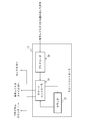
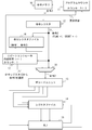
- FIG. 1 is a block diagram showing an arithmetic processing apparatus according to this embodiment.
- the arithmetic processing unit 1 includes an instruction memory 10, a program counter 11, an instruction register 12, a decode unit 13, a register file 14, an ALU (Arithmetic Logic Unit) 15, an instruction register file 16, and a repeat controller 17. , A selector 18.
- the instruction memory 10 stores instructions to be executed.
- the instruction memory 10 is connected to an instruction register 12 and a program counter 11.
- the program counter 11 holds information for supplying an address when reading an instruction from the instruction memory 10. That is, the program counter 11 holds information on instructions to be read from the instruction memory 10.
- the program counter 11 is in an update state or a HOLD state.
- the update state is a state in which information on an instruction to be read can be updated.
- the HOLD state is a state in which information on an instruction to be read cannot be updated.
- the program counter 11 is connected to the instruction memory 10, the repeat controller 17, and the ALU 15.
- the instruction register 12 is a register that temporarily holds an instruction read from the instruction memory 10.
- the instruction register 12 is connected to the selector 18, the repeat controller 17, and the instruction register file 16.
- the decode unit 13 interprets the instruction supplied from the selector 18 and outputs an execution control signal for controlling the register file 14 and ALU 15 existing in the subsequent stage to the register file 14 and ALU 15.
- the decode unit 13 is connected to the selector 18, the register file 14, and the ALU 15.
- the register file 14 stores data used in operations performed by the ALU 15.
- the register file 14 is connected to the decode unit 13 and the ALU 15.
- the ALU 15 is an arithmetic processing unit that performs arithmetic processing using the supplied instruction.
- the ALU 15 is connected to the decode unit 13 and the register file 14.
- the instruction register file 16 temporarily stores instructions to be loop processed. Instructions are supplied from the instruction register 12 to the instruction register file 16. Further, the instruction held in the instruction register file 16 is updated by the operation instruction signal of the repeat controller 17. A specific example of instruction storage by the instruction register file 16 will be described later.
- the instruction register file 16 is connected to the instruction register 12, the repeat controller 17, and the selector 18.
- the repeat controller 17 predecodes a flag indicating a loop process (REP FLAG 31 in FIG. 3 to be described later) and a value indicating a specified number of loop processes (REP COUNT 32 in FIG. 3 to be described later) prior to instruction interpretation by the decode unit 13. To do.
- the repeat controller 17 instructs the instruction register file 16, the selector 18, and the program counter 11 with reference to the internal state and the flag acquired by predecoding.
- the repeat controller 17 is connected to the instruction register 12, the instruction register file 16, the selector 18, and the program counter 11.
- FIG. 2 is a block diagram showing the internal configuration of the repeat controller 17.
- the repeat controller 17 includes a predecoder 20, a counter 21, and a state controller 22.
- the predecoder 20 reads an instruction stored in the instruction register 12 and predecodes the instruction.
- the counter 21 holds a count value for controlling instruction loop processing. This count value indicates the remaining number of loop processes.
- the state machine 22 is in one of three internal states (0 to 2).
- the first state (0) indicates that no instruction exists in the instruction register file 16.
- the second state (1) indicates that an instruction exists in the instruction register file 16.
- the third state (2) indicates that the repeat process is being executed.
- the state machine 22 is connected to the counter 21 and the predecoder 20.
- the counter 21 is connected to the state machine 22.
- the selector 18 selects one of the instruction stored in the instruction register 12 and the instruction stored in the instruction register file 16 and supplies the selected instruction to the decode unit 13.
- the selector 18 performs the selection according to an instruction from the repeat controller 17.
- the selector 18 is connected to the decode unit 13, the instruction register 12, the instruction register file 16, and the repeat controller 17.
- the instruction memory 10 stores at least one instruction necessary for performing desired arithmetic processing.
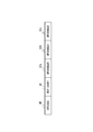
- FIG. 3 is a diagram showing each field of the instruction stored in the instruction memory 10.
- Each instruction includes OPECODE 30, REP FLAG 31, REP COUNT 32, OPERAND # 0 (33a), OPERAND # 1 (33b), and OPERAND # 2 (33c).
- OPECODE 30 is a field indicating the type of instruction.
- REP FLAG31 is a field indicating whether or not the instruction is included in the loop processing.
- REP COUNT 32 is a field indicating the specified number of times of loop processing.
- OPERAND # 0 (33a) is a field indicating an index in which the first data used in the instruction to be executed is stored. The index indicates a position in the register file 14. The same applies to OPERAND # 1 (33b) and OPERAND # 2 (33c).
- OPERAND # 1 (33b) is a field indicating an index in which second data used in an instruction to be executed is stored.
- OPERAND # 2 (33c) is a field indicating an index for storing the operation result of the instruction to be executed.
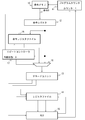
- the value stored in the program counter 11 is referred to, and an instruction corresponding to the value is read from the instruction memory 10.
- the read instruction is stored in the instruction register 12.
- the instruction stored in the instruction register 12 is supplied to the repeat controller 17.
- the instruction is supplied to the instruction register file 16.
- the predecoder 20 in the repeat controller 17 predecodes the supplied instruction.
- predecoding is to read the values of the REP FLAG 31 and REP COUNT 32 of the instruction.
- the predecoder 20 supplies the read values of the REP FLAG 31 and the REP COUNT 32 to the state machine 22.
- the state machine 22 includes a program counter 11 and an instruction register based on the supplied REP FLAG 31 and REP COUNT 32 values, the internal state of the state machine 22 (any one of 0 to 2), and the counter 21 count value.
- the file 16 and the selector 18 are controlled. The control of each processing unit by the state machine 22, the change of the internal state in the state machine 22, and the update of the value of the counter 21 will be described below.
- the state machine 22 instructs the selector 18 to select an instruction from the instruction register 12. Further, the state machine 22 instructs the program counter 11 to transition to the update state. Furthermore, the state machine 22 instructs to discard the latest instruction among the instructions held in the instruction register file 16. The internal state of the state machine 22 remains 0 (no instruction exists in the instruction register file 16).
- the state machine 22 instructs the selector 18 to select an instruction from the instruction register 12. Further, the state machine 22 instructs the program counter 11 to transition to the update state. Further, the state machine 22 updates the count value of the counter 21 to a value obtained by subtracting 1 from the value of the REP COUNT 32 extracted by the predecoder 20. Then, the internal state of the state machine 22 is set to 1 (the instruction exists in the instruction register file 16).
- the internal state is 1 (when an instruction exists in the instruction register file 16)
- the state machine 22 instructs the selector 18 to select an instruction from the instruction register 12. Further, the state machine 22 instructs the program counter 11 to transition to the update state.
- the internal state of the state machine 22 remains 1 (the instruction exists in the instruction register file 16).
- the state machine 22 instructs the instruction register file 16 to discard the latest input instruction. Then, the state machine 22 instructs the selector 18 to read out and output the instruction located at the head of the instruction register file 16 (the instruction input the oldest). Further, the state machine 22 instructs the program counter 11 to transition to the HOLD state. Then, the internal state of the state machine 22 is 2 (during execution of repeat processing).
- the state machine 22 instructs the instruction register file 16 to discard the most recently input instruction. Further, the state machine 22 instructs the program counter 11 to transition to the HOLD state. The internal state of the state machine 22 is 2 (during repeat processing). Then, the state machine 22 instructs the selector 18 to read and output the instruction input next to the instruction read in the previous clock cycle among the instructions in the instruction register file 16. At this time, if the read instruction is at the end of the instruction register file 16 (the most recently input instruction), the count value of the counter 21 is decremented.
- the state machine 22 Only when the count value of the counter 21 becomes 0, the state machine 22 instructs the program counter 11 to transition from the HOLD state to the update state. Further, the state machine 22 instructs to clear the internal data of the instruction register file 16. The internal state of the state machine 22 is 0 (no instruction exists in the instruction register file 16).
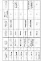
- FIG. 4 is a table showing the control of each processing unit by the state machine 22 described above, the change of the internal state in the state machine 22, and the update of the count value of the counter 21.
- the repeat controller 17 operates.
- the selector 18 selects an instruction according to the operation instruction of the repeat controller 17 and supplies the selected instruction to the decode unit 13.
- the decode unit 13 analyzes the OPECODE 30, the OPERAND # 0 (33a), the OPERAND # 1 (33b), and the OPERAND # 2 (33c) included in the instruction, and the analysis result is stored in the register file 14 and the ALU 15 in the subsequent stage. To supply. In response to this, the register file 14 and the ALU 15 execute a desired instruction.
- the decode unit 13, the register file 14, and the ALU 15 operate as an instruction execution unit that executes the supplied instruction.
- FIG. 5 is a diagram showing instructions stored in the instruction memory 10. As shown in the figure, the instruction memory 10 stores four instructions. The values shown in FIG. 5 are set in REP FLAG 31 and REP COUNT 32 of each instruction. The internal state of the state machine 22 in the repeat controller 17 is 0 in the initial state (no instruction exists in the instruction register file). The count value of the program counter 11 is “1”, which is a value corresponding to the instruction 1.
- FIGS. 6 to 12 show operation images of the arithmetic processing unit in each clock cycle corresponding to the following description.
- the instruction 1 is read from the instruction memory 10 in accordance with the count value “1” of the program counter 11.
- the read instruction 1 is temporarily stored in the instruction register 12. The above operation is shown in FIG.
- the instruction 1 stored in the instruction register 12 is supplied to the instruction register file 16 and the repeat controller 17.
- the predecoder 20 in the repeat controller 17 reads the values of the REP FLAG 31 and REP COUNT 32 of the instruction 1. Since the value of REP FLAG 31 of the instruction 1 is “1” and the internal state of the state machine 22 is “0”, the repeat controller 17 sets the selector 18 to select the instruction read from the instruction register 12. Control. Further, the repeat controller 17 puts the program counter 11 in an updated state.
- the state machine 22 sets “1”, which is a value obtained by subtracting 1 from the value “2” of the REP COUNT 32 to the counter 21.
- the internal state of the state machine 22 is set to “1”.
- the selector 18 selects the instruction 1 supplied from the instruction register 12 and inputs it to the decode unit 13. At the same time, since the program counter 11 is in the update state, the value of the program counter 11 is incremented and changes from “1” to “2”. Since the value of the program counter 11 is “2”, the instruction 2 is read from the instruction memory 10. The read instruction 2 is temporarily stored in the instruction register 12. Note that (command 1) is stored in the command register file 16. The above operation is shown in FIG.
- the instruction 2 stored in the instruction register 12 is supplied to the instruction register file 16 and the repeat controller 17.
- the predecoder 20 in the repeat controller 17 reads the values of the REP FLAG 31 and REP COUNT 32 of the instruction 2. Since the value of REP FLAG 31 of the instruction 2 is “1” and the internal state of the state machine 22 is “1”, the repeat controller 17 sets the selector 18 to select the instruction read from the instruction register 12. Control. Further, the repeat controller 17 puts the program counter 11 in an updated state. The internal state of the state machine 22 is set to “1”. The selector 18 selects the instruction 2 supplied from the instruction register 12 and inputs it to the decode unit 13.
- the instruction 3 stored in the instruction register 12 is supplied to the instruction register file 16 and the repeat controller 17.
- the predecoder 20 in the repeat controller 17 reads the values of the REP FLAG 31 and REP COUNT 32 of the instruction 3. Since the value of REP FLAG 31 of the instruction 3 is “0” and the internal state of the state machine 22 is “1”, the repeat controller 17 instructs the instruction register file 16 to discard the instruction 3. Then, the repeat controller 17 controls the selector 18 to read and output the instruction 1 stored at the head of the instruction register file 16. Further, the repeat controller 17 sets the program counter 11 to the HOLD state. The internal state of the state machine 22 is set to “2”.
- the selector 18 inputs the instruction 1 read from the instruction register file 16 to the decode unit 13. Since the program counter 11 is in the HOLD state, the value of the program counter 11 does not count up and remains “3”.
- the read instruction 3 is temporarily stored in the instruction register 12. Since the instruction 3 is discarded, the instruction register file 16 is in a state where (instruction 1, instruction 2) is stored. The above operation is shown in FIG.
- the instruction 3 stored in the instruction register 12 is supplied to the instruction register file 16 and the repeat controller 17.
- the predecoder 20 in the repeat controller 17 reads the values of the REP FLAG 31 and REP COUNT 32 of the instruction 3. Since the value of REP FLAG 31 of the instruction 3 is “0” and the internal state of the state machine 22 is “2”, the repeat controller 17 instructs the instruction register file 16 to discard the instruction 3. Then, the repeat controller 17 controls the selector 18 so that the instruction 2 that is the instruction next to the instruction 1 output in the previous cycle is read from the instruction register file 16 and output. As a result, since all the instructions stored in the instruction register file 16 have been read, the count value of the counter 21 is decremented.
- the count value of the counter 21 becomes “0” by decrement. Since the count value of the counter 21 has become “0”, the repeat controller 17 puts the program counter 11 in the update state. The internal state of the state machine 22 is set to “0”. Further, the repeat controller 17 clears the instruction group held in the instruction register file 16. The selector 18 inputs the instruction 2 read from the instruction register file 16 to the decode unit 13. Since the program counter 11 is in the HOLD state, the value of the program counter 11 is not counted up and remains “3”. The read instruction 3 is temporarily stored in the instruction register 12. Note that no instruction is stored in the instruction register file 16. The above operation is shown in FIG.
- the instruction 3 stored in the instruction register 12 is supplied to the instruction register file 16 and the repeat controller 17.
- the predecoder 20 in the repeat controller 17 reads the values of the REP FLAG 31 and REP COUNT 32 of the instruction 3. Since the value of REP FLAG 31 of the instruction 3 is “0” and the internal state of the state machine 22 is “0”, the repeat controller 17 instructs the instruction register file 16 to discard the instruction 3.
- the repeat controller 17 controls the selector 18 so as to select the instruction read from the instruction register 12. Further, the repeat controller 17 puts the program counter 11 in an updated state.
- the internal state of the state machine 22 is set to “0”.
- the selector 18 selects the instruction 3 supplied from the instruction register 12 and inputs it to the decode unit 13.
- the instruction 4 stored in the instruction register 12 is supplied to the instruction register file 16 and the repeat controller 17.
- the predecoder 20 in the repeat controller 17 reads the values of the REP FLAG 31 and REP COUNT 32 of the instruction 4. Since the value of REP FLAG 31 of the instruction 4 is “0” and the internal state of the state machine 22 is “0”, the repeat controller 17 instructs the instruction register file 16 to discard the instruction 4.
- the repeat controller 17 controls the selector 18 so as to select the instruction read from the instruction register 12. Further, the repeat controller 17 puts the program counter 11 in an updated state.
- the internal state of the state machine 22 is set to “0”.
- the selector 18 selects the instruction 4 supplied from the instruction register 12 and inputs it to the decode unit 13.
- each instruction includes a flag (REP FLAG31) indicating whether or not it is included in an instruction group (including one or more instructions) that is a target of loop processing, and a specified number of loop processing (REP COUNT32). ) And are stipulated.
- the repeat controller 17 controls instruction execution according to the internal state (0 to 2), the count value held by the counter 21 (that is, a value representing the number of executions of loop processing), and the value of the REP FLAG 31. That is, the repeat controller 17 performs update / HOLD setting of the program counter 11, update of the instruction register file 16 and determination of an instruction to be read, and control of the operation of the selector 18.
- the repeat controller 17 treats consecutive instructions in which “1” is set in the flag (REP FLAG31) as an instruction group to be loop-processed. That is, the repeat controller 17 can repeatedly execute a plurality of instructions as one unit without processing a new instruction by interpreting information (REP FLAG31, REP COUNT32) included in each instruction. In other words, the arithmetic processing device according to the present embodiment can repeatedly execute a plurality of instructions as one unit without increasing the number of input instructions.
- the field structure of the command shown in FIG. 3 is merely an example, and may include other fields.
- the configurations of the decode unit 13 to which the selector 18 supplies instructions, the subsequent register file 14 and the ALU 15 are not limited to those shown in FIG. 1, and can be changed as appropriate according to the type of operation.
- the instructions to be processed by the arithmetic processing unit are related to information indicating the range of instructions subject to loop processing (for example, loop processing of three instructions together) and the number of loop processes. In other words, it can be said to have provision information.
- the repeat controller 16 controls the arithmetic processing by interpreting the information (REP ⁇ FLAG31 and REP COUNT32) included in the instruction.
- the controlling processing unit may interpret the information and control the instruction read from the instruction memory 12. That is, the program counter 11 or a processing unit that controls the program counter 11 may determine one instruction to be supplied to the decode unit 13 based on these pieces of information, read this instruction, and supply it to the decode unit 13.
- the arithmetic processing apparatus according to the present embodiment is characterized in that the same processing as that of the arithmetic processing apparatus according to the first embodiment can be performed even if the instruction does not have the field REP FLAG 31 described above.
- the arithmetic processing apparatus according to the present embodiment will be described focusing on differences from the arithmetic processing apparatus according to the first embodiment.
- FIG. 13 is a diagram illustrating each field of an instruction handled by the arithmetic processing device according to the present embodiment.
- Each instruction includes OPECODE 40, REP COUNT 41, OPERAND # 0 (42a), OPERAND # 1 (42b), and OPERAND # 2 (42c).
- Each instruction does not have a field corresponding to REP FLAG31.
- OPECODE 40, OPERAND # 0 (42a), OPERAND # 1 (42b), and OPERAND # 2 (42c) are the above-mentioned OPECODE30, OPERAND # 0 (33a), OPERAND # 1 (33b), and OPERAND # 2 (33c). Used in almost the same application.
- REP COUNT41 can take an integer of 0 or more.
- the loop processing is executed simultaneously with the previously issued instruction in which “2” or more is set in the REP COUNT 41.
- the instruction according to the present embodiment can be reduced in size by the bit width corresponding to the field of the REP FLAG 31 as compared with the first embodiment.
- the memory scale can be reduced.
- the overall configuration of the arithmetic processing apparatus according to the present embodiment is the same as that of the arithmetic processing apparatus according to the first embodiment (FIG. 1). Also, the internal configuration of the repeat controller 17 is the same as that of the arithmetic processing apparatus (FIG. 2) according to the first embodiment.
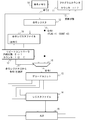
- an instruction corresponding to the count value is read from the instruction memory 10.
- the read instruction is stored in the instruction register 12.
- the instruction stored in the instruction register 12 is supplied to the repeat controller 17.
- the instruction is supplied to the instruction register file 16.
- the predecoder 20 in the repeat controller 17 predecodes the supplied instruction.
- predecoding means reading the value of the REP COUNT 41 of the instruction.
- the predecoder 20 supplies the read value of the REP COUNT 41 to the state machine 22.
- the state machine 22 Based on the supplied REP COUNT 41 value, the internal state of the state machine 22 (any one of 0 to 2), and the counter 21 count value, the state machine 22 The selector 18 is controlled. The control of each processing unit by the state machine 22, the change of the internal state in the state machine 22, and the update of the count value of the counter 21 will be described below.
- the state machine 22 instructs the selector 18 to select an instruction from the instruction register 12. Further, the state machine 22 instructs the program counter 11 to transition to the update state. Furthermore, the state machine 22 instructs to discard the latest instruction among the instructions held in the instruction register file 16. The internal state of the state machine 22 remains 0 (no instruction exists in the instruction register file 16).
- the state machine 22 instructs the selector 18 to select an instruction from the instruction register 12. Further, the state machine 22 instructs the program counter 11 to transition to the update state. Further, the state machine 22 updates the count value of the counter 21 to a value obtained by subtracting 1 from the value of the REP COUNT 41 extracted by the predecoder 20. Then, the internal state of the state machine 22 is set to 1 (the instruction exists in the instruction register file 16).
- the state machine 22 instructs the selector 18 to select an instruction from the instruction register 12. Further, the state machine 22 instructs the program counter 11 to transition to the update state. The internal state of the state machine 22 remains 1 (the instruction exists in the instruction register file 16).
- the state machine 22 instructs the instruction register file 16 to discard the latest input instruction. Then, the state machine 22 instructs the selector 18 to read out and output the instruction located at the head of the instruction register file 16 (the instruction input the oldest). Further, the state machine 22 instructs the program counter 11 to transition to the HOLD state. Then, the internal state of the state machine 22 is 2 (during execution of repeat processing).
- the state machine 22 instructs the instruction register file 16 to discard the latest input instruction. Further, the state machine 22 instructs the program counter 11 to transition to the HOLD state. The internal state of the state machine 22 is 2 (during repeat processing). Then, the state machine 22 instructs the selector 18 to read and output the instruction input next to the instruction read in all clock cycles among the instructions in the instruction register file 16. At this time, if the read instruction is at the end of the instruction register file 16 (the most recently input instruction), the count value of the counter 21 is decremented.
- the state machine 22 Only when the count value of the counter 21 becomes 0, the state machine 22 instructs the program counter 11 to transition from the HOLD state to the update state. Further, the state machine 22 instructs to clear the internal data of the instruction register file 16. The internal state of the state machine 22 is 0 (no instruction exists in the instruction register file).
- FIG. 14 is a table showing the control of each processing unit by the state machine 22 described above, the change of the internal state in the state machine 22, and the update of the count value of the counter 21.
- the repeat controller 17 operates.
- the selector 18 selects an instruction according to the operation instruction of the repeat controller 17 and supplies the selected instruction to the decode unit 13.
- the decode unit 13 analyzes the OPECODE 40, OPERAND # 0 (42a), OPERAND # 1 (42b), and OPERAND # 2 (42c) included in the instruction, and the analysis result is sent to the register file 14 and the ALU 15 in the subsequent stage. To supply.
- the register file 14 and the ALU 15 execute a desired instruction.
- the decode unit 13, the register file 14, and the ALU 15 operate as an instruction execution unit that executes the supplied instruction.
- FIG. 15 is a diagram showing instructions stored in the instruction memory 10.
- the instruction memory 10 stores four instructions.
- the internal state of the state machine 22 in the repeat controller 17 is 0 in the initial state (no instruction exists in the instruction register file).
- the count value of the program counter 11 is “1”, which is a value corresponding to the instruction 1.
- the operation conceptual diagrams from the first clock cycle to the seventh clock cycle are substantially the same as those shown in FIGS. 6 to 12 (except that the REP FLAG is not included in the instruction), and the illustration is omitted.
- the instruction 1 is read from the instruction memory 10 in accordance with the count value “1” of the program counter 11.
- the read instruction 1 is temporarily stored in the instruction register 12.
- the instruction 1 stored in the instruction register 12 is supplied to the instruction register file 16 and the repeat controller 17.
- the predecoder 20 in the repeat controller 17 reads the value of the REP COUNT 41 of the instruction 1. Since the value of REP COUNT 41 of the instruction 1 is “2” and the internal state of the state machine 22 is “0”, the repeat controller 17 sets the selector 18 to select the instruction read from the instruction register 12. Control. Further, the repeat controller 17 puts the program counter 11 in an updated state.
- the state machine 22 sets “1”, which is a value obtained by subtracting 1 from the value “2” of the REP COUNT 32 to the counter 21.
- the internal state of the state machine 22 is set to “1”.
- the selector 18 selects the instruction 1 supplied from the instruction register 12 and inputs it to the decode unit 13. At the same time, since the program counter 11 is in the update state, the value of the program counter 11 is incremented and changes from “1” to “2”. Since the value of the program counter 11 is “2”, the instruction 2 is read from the instruction memory 10. The read instruction 2 is temporarily stored in the instruction register 12. Note that (command 1) is stored in the command register file 16.
- the instruction 2 stored in the instruction register 12 is supplied to the instruction register file 16 and the repeat controller 17.
- the predecoder 20 in the repeat controller 17 reads the value of the REP COUNT 41 of the instruction 2. Since the value of REP COUNT 41 of the instruction 2 is “0” and the internal state of the state machine 22 is “1”, the repeat controller 17 sets the selector 18 to select the instruction read from the instruction register 12. Control. Further, the repeat controller 17 puts the program counter 11 in an updated state. The internal state of the state machine 22 is set to “1”.
- the selector 18 selects the instruction 2 supplied from the instruction register 12 and inputs it to the decode unit 13.
- the instruction 3 is read from the instruction memory 10.
- the read instruction 3 is temporarily stored in the instruction register 12.
- the instruction register file 16 stores (instruction 1, instruction 2).
- the instruction 3 stored in the instruction register 12 is supplied to the instruction register file 16 and the repeat controller 17.
- the predecoder 20 in the repeat controller 17 reads the value of the REP COUNT 41 of the instruction 3. Since the value of REP COUNT 41 of the instruction 3 is “1” and the internal state of the state machine 22 is “1”, the repeat controller 17 instructs the instruction register file 16 to discard the instruction 3. Then, the repeat controller 17 controls the selector 18 to read and output the instruction 1 stored at the head of the instruction register file 16. Further, the repeat controller 17 sets the program counter 11 to the HOLD state. The internal state of the state machine 22 is set to “2”. The selector 18 inputs the instruction 1 read from the instruction register file 16 to the decode unit 13.
- the program counter 11 Since the program counter 11 is in the HOLD state, the value of the program counter 11 does not count up and remains “3”.
- the read instruction 3 is temporarily stored in the instruction register 12. Since the instruction 3 is discarded, the instruction register file 16 is in a state where (instruction 1, instruction 2) is stored.
- the instruction 3 stored in the instruction register 12 is supplied to the instruction register file 16 and the repeat controller 17.
- the predecoder 20 in the repeat controller 17 reads the value of the REP COUNT 41 of the instruction 3. Since the value of REP COUNT 41 of the instruction 3 is “1” and the internal state of the state machine 22 is “2”, the repeat controller 17 instructs the instruction register file 16 to discard the instruction 3. Then, the repeat controller 17 controls the selector 18 to read and output the instruction 2 that is the instruction next to the instruction 1 output in the previous cycle. As a result, since all the instructions stored in the instruction register file 16 have been read, the count value of the counter 21 is decremented. The count value of the counter 21 becomes “0” by decrement.
- the repeat controller 17 Since the count value of the counter 21 has become “0”, the repeat controller 17 puts the program counter 11 in the update state. The internal state of the state machine 22 is set to “0”. Further, the repeat controller 17 clears the instruction group held in the instruction register file 16. The selector 18 inputs the instruction 2 read from the instruction register file 16 to the decode unit 13. Since the program counter 11 is in the HOLD state, the value of the program counter 11 is not counted up and remains “3”. The read instruction 3 is temporarily stored in the instruction register 12. Note that no instruction is stored in the instruction register file 16.
- the instruction 3 stored in the instruction register 12 is supplied to the instruction register file 16 and the repeat controller 17.
- the predecoder 20 in the repeat controller 17 reads the value of the REP COUNT 41 of the instruction 3. Since the value of REP COUNT 41 of the instruction 3 is “1” and the internal state of the state machine 22 is “0”, the repeat controller 17 instructs the instruction register file 16 to discard the instruction 3.
- the repeat controller 17 controls the selector 18 so as to select the instruction read from the instruction register 12. Further, the repeat controller 17 puts the program counter 11 in an updated state.
- the internal state of the state machine 22 is set to “0”.
- the selector 18 selects the instruction 3 supplied from the instruction register 12 and inputs it to the decode unit 13.
- the value of the program counter 11 is incremented and changes from “3” to “4”. Since the value of the program counter 11 is “4”, the instruction 4 is read from the instruction memory 10. The read instruction 4 is temporarily stored in the instruction register 12.
- the instruction 4 stored in the instruction register 12 is supplied to the instruction register file 16 and the repeat controller 17.
- the predecoder 20 in the repeat controller 17 reads the value of the REP COUNT 41 of the instruction 4. Since the value of REP COUNT 41 of the instruction 4 is “1” and the internal state of the state machine 22 is “0”, the repeat controller 17 instructs the instruction register file 16 to discard the instruction 4.
- the repeat controller 17 controls the selector 18 so as to select the instruction read from the instruction register 12. Further, the repeat controller 17 puts the program counter 11 in an updated state.
- the internal state of the state machine 22 is set to “0”.
- the selector 18 selects the instruction 4 supplied from the instruction register 12 and inputs it to the decode unit 13.
- the arithmetic processing apparatus handles the commands shown in FIG.
- the instruction shown in FIG. 13 does not include the REP FLAG 31 described above. That is, the data size of the instruction shown in FIG. 13 is smaller by the field width of REP FLAG 31 than the instruction shown in FIG. As a result, the memory scale can be reduced.
- the arithmetic processing apparatus can appropriately handle loop processing of a single instruction as shown in FIG. That is, when the instruction shown in FIG. 16 is a processing target, the arithmetic processing apparatus according to the present embodiment is an instruction 1 ⁇ an instruction 2 ⁇ an instruction 1 ⁇ an instruction 2 ⁇ an instruction 1 ⁇ an instruction 1 ⁇ an instruction 2 ⁇ an instruction 2 ⁇ Processing can be performed as instruction 3 ⁇ instruction 4.
- the field configuration of the instruction shown in FIG. 13 is merely an example, and may include other fields. Furthermore, the configurations of the decode unit 13 to which the selector 18 supplies instructions, the subsequent register file 14 and the ALU 15 are not limited to those shown in FIG. 1, and can be changed as appropriate according to the type of operation.
- a program counter for sequentially specifying addresses of instructions to be read from the instruction storage means in which instructions to be executed by the instruction execution means are stored; Instruction saving means for saving an instruction group including one or more instructions to be loop-processed among the instructions designated by the program counter and read from the instruction storage means; A repeat controller for controlling a command to be supplied to the command execution means based on management information indicating whether or not to perform the loop processing included in the command and a prescribed number of times of the loop processing; Selection means for selecting either an instruction read from the instruction storage means or an instruction output from the instruction saving means based on the control of the repeat controller and supplying the instruction execution means to the instruction execution means; ,
- the management information includes information indicating whether or not the instruction read from the instruction storage means is an instruction processed in one loop process,
- the repeat controller saves the instruction group processed in the one loop process in the instruction save unit based on the management information, and all instructions processed in the one loop process are saved in the instruction save unit.
- the update of the address specified by the program counter is stopped, and one instruction to be processed is output from the instruction group held in the instruction saving unit, and during the execution of the loop processing, the selection unit An arithmetic processing unit that selectively outputs an instruction output from the instruction saving means.
- the specified number of times of the loop processing in the management information is the first information, and information indicating whether or not the instruction read from the instruction storage means is an instruction to be processed by the one loop processing is the second information If the information of Each of the instructions comprises a repeat number field indicating the first information; 2.
- Appendix 4 An instruction temporary holding means for temporarily storing an instruction designated by the program counter and read from the instruction storage means;
- the selection means and the instruction saving means acquire an instruction read from the instruction storage means via the instruction temporary holding means, according to any one of appendix 1 to appendix 3, Arithmetic processing unit.
- the repeat controller holds an internal state indicating an instruction execution state and an instruction save state to the save means, and based on the internal state and the management information, saves instructions to the instruction save means, the program counter
- the arithmetic processing unit according to any one of appendix 1 to appendix 4, wherein control of an address designated by the controller and selection processing by the selection unit is performed.
- the internal state includes a first state in which the instruction saving unit does not hold the instruction group, a second state in which the instruction saving unit holds the instruction group, and a third state indicating that the one loop process is being executed.
- the repeat controller is A predecoder for reading the management information from the instruction;
- the internal state of the next cycle is determined according to the current internal state and the management information read by the predecoder, instruction saving processing to the instruction saving means, and update of the address specified by the program counter
- a state controller for controlling the selection process by the selection unit;
- the arithmetic processing apparatus according to appendix 5 or appendix 6, further comprising: a counter that holds a count value that is the current execution count of the one loop process.
- Appendix 9 The arithmetic processing apparatus according to any one of appendices 1 to 8, further comprising the instruction storage unit.
- the state controller sends the instruction temporary to the selection unit.
- the instruction output from the holding means is selected, the updating of the address by the program counter is continued, the latest instruction input to the instruction saving means is discarded,
- the state controller sends the instruction temporary to the selection unit.
- the internal state is set to the second state, and the counter decrements the count value
- the state controller sends the instruction temporary to the selection unit.
- the instruction output from the holding means is selected, the updating of the address by the program counter is continued,
- the state controller saves the instruction in the selection unit.
- the instruction following the instruction read most recently from the instruction group in the means is read and selected, the address update by the program counter is stopped, and the latest instruction input to the instruction saving means is discarded. Later, the internal state becomes the third state, When the internal state is the third state, the second information is a value indicating that the instruction is not processed by the one loop process, and the count value is not 0, the state controller
- the selection means reads and selects an instruction following the instruction most recently read from the instruction group in the instruction saving means, stops updating the address by the program counter, and is input to the instruction saving means When the latest instruction is discarded, the internal state is changed to the third state, and the counter is set when the instruction selected by the selection unit is the last of the instruction group held by the instruction saving unit.
- the instruction to be processed includes management information indicating whether or not to perform loop processing and the specified number of times of the loop processing, and the management information is processed in one loop processing when the instruction read from the instruction storage means is processed. Information indicating whether or not Based on the management information, among instructions read out from the instruction storage unit, an instruction group including one or more instructions to be loop processed is saved, and all instructions processed in one loop process are saved. The update of the instruction read out from the instruction storage unit is stopped, and during execution of the one loop process, one instruction to be processed is output from the saved instruction group to the instruction execution unit, and other than the loop process An arithmetic processing method for outputting an instruction read from the instruction storage means to the instruction execution means during instruction execution.
- the specified number of times of the loop processing in the management information is the first information, and information indicating whether or not the instruction read from the instruction storage means is an instruction to be processed by the one loop processing is the second information If the information of Each of the instructions comprises a repeat number field indicating the first information; 12.
- the present invention can be applied to stream processing in which a single processing is performed on a large number of data, specifically to signal processing such as filtering processing and data sorting processing.
Landscapes
- Engineering & Computer Science (AREA)
- Software Systems (AREA)
- Theoretical Computer Science (AREA)
- Physics & Mathematics (AREA)
- General Engineering & Computer Science (AREA)
- General Physics & Mathematics (AREA)
- Executing Machine-Instructions (AREA)
- Advance Control (AREA)
Abstract
Selon l'invention, chaque instruction contient des informations de drapeau spécifiant un groupe d'instructions qui effectue un processus en boucle et des informations de gestion relatives au nombre d'itérations du processus en boucle. Un fichier de registre d'instructions (16) sauvegarde le groupe d'instructions traité dans un processus en boucle. Sous la commande d'un contrôleur de répétition (17), un sélecteur (18) sélectionne et délivre une instruction qui est délivrée par un registre d'instructions (12) ou une instruction qui est délivrée par le fichier de registres d'instructions (16). En réponse aux informations de gestion incluses dans l'instruction, et à l'état interne, le contrôleur de répétition (17) commande un compteur ordinal (12), la lecture d'instructions dans le fichier de registres d'instructions (16) et la mise à jour de son état de stockage, et le processus de sélection du sélecteur (18).
Priority Applications (1)
| Application Number | Priority Date | Filing Date | Title |
|---|---|---|---|
| JP2013516201A JP6191457B2 (ja) | 2011-05-20 | 2012-05-18 | 演算処理装置、演算処理方法 |
Applications Claiming Priority (2)
| Application Number | Priority Date | Filing Date | Title |
|---|---|---|---|
| JP2011-113395 | 2011-05-20 | ||
| JP2011113395 | 2011-05-20 |
Publications (1)
| Publication Number | Publication Date |
|---|---|
| WO2012160794A1 true WO2012160794A1 (fr) | 2012-11-29 |
Family
ID=47216887
Family Applications (1)
| Application Number | Title | Priority Date | Filing Date |
|---|---|---|---|
| PCT/JP2012/003269 Ceased WO2012160794A1 (fr) | 2011-05-20 | 2012-05-18 | Dispositif de traitement arithmétique et procédé de traitement arithmétique |
Country Status (2)
| Country | Link |
|---|---|
| JP (1) | JP6191457B2 (fr) |
| WO (1) | WO2012160794A1 (fr) |
Citations (9)
| Publication number | Priority date | Publication date | Assignee | Title |
|---|---|---|---|---|
| JPS6446835A (en) * | 1987-08-17 | 1989-02-21 | Oki Electric Ind Co Ltd | Program translating method |
| JPH04293124A (ja) * | 1991-03-20 | 1992-10-16 | Hitachi Ltd | データ処理プロセッサ |
| JPH04364526A (ja) * | 1991-06-11 | 1992-12-16 | Gijutsu Kenkyu Kumiai Kokusai Fuajii Kogaku Kenkyusho | 繰り返し演算制御装置 |
| JPH07160585A (ja) * | 1993-12-13 | 1995-06-23 | Hitachi Ltd | 低電力データ処理装置 |
| JP2000507009A (ja) * | 1996-03-15 | 2000-06-06 | マイクロン・テクノロジイ・インコーポレーテッド | 単一の命令に応答して演算を複数回実行する方法および装置 |
| JP2003108368A (ja) * | 2001-10-01 | 2003-04-11 | Nec Corp | 並列演算プロセッサ、その演算制御方法及びプログラム |
| JP2003248670A (ja) * | 2001-12-19 | 2003-09-05 | Sony Corp | プロセッサ |
| JP2006508447A (ja) * | 2002-11-28 | 2006-03-09 | コーニンクレッカ フィリップス エレクトロニクス エヌ ヴィ | データ・プロセッサ用ループ制御回路 |
| JP2009054032A (ja) * | 2007-08-28 | 2009-03-12 | Toshiba Corp | 並列プロセッサ |
-
2012
- 2012-05-18 WO PCT/JP2012/003269 patent/WO2012160794A1/fr not_active Ceased
- 2012-05-18 JP JP2013516201A patent/JP6191457B2/ja active Active
Patent Citations (9)
| Publication number | Priority date | Publication date | Assignee | Title |
|---|---|---|---|---|
| JPS6446835A (en) * | 1987-08-17 | 1989-02-21 | Oki Electric Ind Co Ltd | Program translating method |
| JPH04293124A (ja) * | 1991-03-20 | 1992-10-16 | Hitachi Ltd | データ処理プロセッサ |
| JPH04364526A (ja) * | 1991-06-11 | 1992-12-16 | Gijutsu Kenkyu Kumiai Kokusai Fuajii Kogaku Kenkyusho | 繰り返し演算制御装置 |
| JPH07160585A (ja) * | 1993-12-13 | 1995-06-23 | Hitachi Ltd | 低電力データ処理装置 |
| JP2000507009A (ja) * | 1996-03-15 | 2000-06-06 | マイクロン・テクノロジイ・インコーポレーテッド | 単一の命令に応答して演算を複数回実行する方法および装置 |
| JP2003108368A (ja) * | 2001-10-01 | 2003-04-11 | Nec Corp | 並列演算プロセッサ、その演算制御方法及びプログラム |
| JP2003248670A (ja) * | 2001-12-19 | 2003-09-05 | Sony Corp | プロセッサ |
| JP2006508447A (ja) * | 2002-11-28 | 2006-03-09 | コーニンクレッカ フィリップス エレクトロニクス エヌ ヴィ | データ・プロセッサ用ループ制御回路 |
| JP2009054032A (ja) * | 2007-08-28 | 2009-03-12 | Toshiba Corp | 並列プロセッサ |
Also Published As
| Publication number | Publication date |
|---|---|
| JP6191457B2 (ja) | 2017-09-06 |
| JPWO2012160794A1 (ja) | 2014-07-31 |
Similar Documents
| Publication | Publication Date | Title |
|---|---|---|
| GB2510655A (en) | Prioritising instructions in queues according to category of instruction | |
| CN103119555B (zh) | 下一指令类型字段 | |
| US20080141013A1 (en) | Digital processor with control means for the execution of nested loops | |
| JP2009163624A (ja) | プロセッサ装置及び条件分岐処理方法 | |
| US9804853B2 (en) | Apparatus and method for compressing instruction for VLIW processor, and apparatus and method for fetching instruction | |
| KR20160110529A (ko) | 파이프라인 제어 신호들을 발생시키도록 프로세서를 인에이블링하기 위한 방법 및 장치 | |
| US11366669B2 (en) | Apparatus for preventing rescheduling of a paused thread based on instruction classification | |
| CN108319559B (zh) | 用于控制矢量内存存取的数据处理装置及方法 | |
| EP3264263A1 (fr) | Surveillance et gestion séquentielles de segments de code pour parallélisation au stade de l'exécution | |
| JP2020502669A (ja) | ベクトル生成命令 | |
| US11669366B2 (en) | Reduction of a number of stages of a graph streaming processor | |
| KR100316710B1 (ko) | 병렬 프로세서를 위한 무순서 명령어 발행 방법 및 장치 | |
| JP6191457B2 (ja) | 演算処理装置、演算処理方法 | |
| JP2017228213A (ja) | 演算処理装置及び演算処理装置の制御方法 | |
| JP5333433B2 (ja) | 低コストに複数命令流を実行するプロセッサ、その方法及びそのプログラム | |
| US9207922B2 (en) | Compiling method and apparatus for scheduling block in pipeline | |
| JP2009069960A (ja) | 分岐予測装置、分岐予測方法、及びマイクロプロセッサ | |
| JP6064993B2 (ja) | 演算処理装置、その演算処理方法、及び演算処理プログラム | |
| KR101118593B1 (ko) | Vliw 명령어 처리 장치 및 방법 | |
| JP5573038B2 (ja) | マルチスレッドプロセッサ及びプログラム | |
| JP5013966B2 (ja) | 演算処理装置 | |
| JP2010140398A (ja) | データ処理装置及びデータ処理方法 | |
| JP2006285721A (ja) | 演算処理装置および演算処理方法 | |
| Oehler | Reduced instruction set computer (RISC) | |
| JP2012008622A (ja) | 演算ユニット |
Legal Events
| Date | Code | Title | Description |
|---|---|---|---|
| 121 | Ep: the epo has been informed by wipo that ep was designated in this application |
Ref document number: 12789014 Country of ref document: EP Kind code of ref document: A1 |
|
| ENP | Entry into the national phase |
Ref document number: 2013516201 Country of ref document: JP Kind code of ref document: A |
|
| NENP | Non-entry into the national phase |
Ref country code: DE |
|
| 122 | Ep: pct application non-entry in european phase |
Ref document number: 12789014 Country of ref document: EP Kind code of ref document: A1 |