WO2012164810A1 - Spectromètre à transformée de fourier et procédé de spectroscopie à transformée de fourier - Google Patents
Spectromètre à transformée de fourier et procédé de spectroscopie à transformée de fourier Download PDFInfo
- Publication number
- WO2012164810A1 WO2012164810A1 PCT/JP2012/002577 JP2012002577W WO2012164810A1 WO 2012164810 A1 WO2012164810 A1 WO 2012164810A1 JP 2012002577 W JP2012002577 W JP 2012002577W WO 2012164810 A1 WO2012164810 A1 WO 2012164810A1
- Authority
- WO
- WIPO (PCT)
- Prior art keywords
- light
- output
- fourier transform
- unit
- measurement
- Prior art date
- Legal status (The legal status is an assumption and is not a legal conclusion. Google has not performed a legal analysis and makes no representation as to the accuracy of the status listed.)
- Ceased
Links
Images





Classifications
-
- G—PHYSICS
- G01—MEASURING; TESTING
- G01J—MEASUREMENT OF INTENSITY, VELOCITY, SPECTRAL CONTENT, POLARISATION, PHASE OR PULSE CHARACTERISTICS OF INFRARED, VISIBLE OR ULTRAVIOLET LIGHT; COLORIMETRY; RADIATION PYROMETRY
- G01J3/00—Spectrometry; Spectrophotometry; Monochromators; Measuring colours
- G01J3/28—Investigating the spectrum
- G01J3/45—Interferometric spectrometry
- G01J3/453—Interferometric spectrometry by correlation of the amplitudes
- G01J3/4535—Devices with moving mirror
Definitions
- the present invention relates to a Fourier transform spectrometer and a Fourier transform spectroscopic method, and is particularly suitable for generating an interferogram used to obtain a spectrum of measured light by integrating a plurality of interferograms.
- the present invention relates to a Fourier transform spectrometer and a Fourier transform spectroscopic method capable of integrating a plurality of interferograms.
- the spectrometer is a device that measures the spectrum of the light to be measured, one of which is an interferometer that measures the interference light of the light to be measured, and Fourier transforms the measurement result to obtain the spectrum of the light to be measured. There is a Fourier transform spectrometer that calculates
- the output of the interferometer is a composite waveform in which light of a plurality of wavelengths included in the light to be measured is collectively interfered by the interferometer, and is generally called an interferogram.
- the spectrum of the light to be measured is obtained by Fourier transforming the interferogram.
- This interferogram has a profile that has one or a plurality of steep peaks in a predetermined range and a substantially zero level in the remaining range, and the center peak of the one or more steep peaks has a center burst. Called.
- a Fourier transform spectrometer when the spectrum of the light to be measured is obtained by Fourier transforming the interferogram obtained in one measurement, the signal-to-noise ratio is usually poor and results with good accuracy can be obtained. hard. For this reason, in a Fourier transform spectrometer, an interferogram is measured a plurality of times for one measurement object, and the plurality of interferograms are integrated to obtain a spectrum of light to be measured. An interferogram (hereinafter referred to as “integrated interferogram”) is generated. These measurements are usually performed while continuously changing the optical path length of one of the two optical paths of the interferometer.
- Patent Document 1 A technique for integrating such a plurality of interferograms is disclosed in, for example, Patent Document 1 and Patent Document 2.
- the interferogram integrating device disclosed in Patent Document 1 is an interferogram integrating device that integrates a plurality of unit interferograms obtained by irradiating an object to be measured with one scan of interference light, the unit interferogram.
- a unit interferogram storage means for temporarily storing a gram, a maximum position detection means for detecting a center burst position from unit interferogram data stored in the unit interferogram storage means, and a maximum position detection means
- the unit interferogram is cut in predetermined amounts on both sides on the position axis of the unit interferogram, and a cutting means for collecting the cut interferogram, and a plurality of cutting means Obtained sequentially corresponding to the unit interferogram And a integrator for integrating the cut interferogram number.
- a measurement light interferogram generated when measurement light passes through the measurement target and a reference light interferogram generated by bypassing the measurement target are measured in synchronization with each other.
- the phase difference that most closely matches the phase of the reference light interferogram in the current measurement cycle is calculated with respect to the reference light interferogram that is stored in advance in the reference waveform storage unit.
- the average of the measurement light interferogram and the reference light interferogram is obtained by synchronously adding based on the obtained phase difference.
- measurement data in a range including the center burst is extracted from a plurality of measurement data (measurement data at each sampling point) obtained by one measurement, and then the measurement of the same optical path difference is performed. Data is found, and then the measured data with the same optical path difference are added together.
- the present invention has been made in view of the above-described circumstances, and its object is to suitably integrate a plurality of interferograms by more appropriately extracting measurement data in a range including the interferogram.
- a Fourier transform type spectrometer and a Fourier transform type spectroscopic method are provided.
- a plurality of interferograms generated by an interferometer that generates an optical path difference between two optical paths by using vibrations are integrated and obtained by this.
- the spectrum of the light to be measured is obtained by Fourier transforming the obtained integrated interferogram.
- the predetermined range to be extracted is set according to the amplitude information of the vibration. For this reason, the Fourier transform spectrometer and the Fourier transform spectroscopic method having such a configuration can take out the measurement data in a range including the interferogram more appropriately because the amplitude information of the vibration is taken into consideration. Therefore, a plurality of interferograms can be preferably integrated.
- FIG. 1st Embodiment It is a block diagram which shows the structure of the Fourier-transform type spectrometer in 1st Embodiment. It is a figure which mainly shows the structure of the interferometer in a Fourier-transform type spectrometer.
- mold spectrometer it is a figure which shows the waveform (interferogram) of the interference light of the to-be-measured light measured as an example.
- mold spectrometer it is a figure which shows the interference waveform of the laser beam of the light source for position measurement measured as an example. It is a figure for demonstrating the predetermined range taken out by an extraction part. It is a figure which shows the relationship between an interferogram and a window function.
- FIG. (1) shows the structure of the Fourier-transform type spectrometer in 2nd Embodiment. It is a figure which shows the spectrum of the laser beam radiated
- mold spectrometer it is a figure which shows the interference waveform of the laser beam with the predetermined
- FIG. 1 is a block diagram showing a configuration of a Fourier transform spectrometer in the first embodiment.
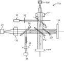
- FIG. 2 is a diagram mainly showing the configuration of the interferometer in the Fourier transform spectrometer.
- the Fourier transform spectrometer Da is an apparatus for measuring the spectrum of the light to be measured as a measurement object, and measures the light to be measured with an interferometer, and the interference light of the measured light to be measured.
- This is a device for obtaining the spectrum of the light to be measured by Fourier transforming the waveform (interferogram).
- the transform target to be Fourier transformed to obtain the spectrum of the light to be measured is An integrated interferogram obtained by integrating a plurality of interferograms of the light to be measured generated by an interferometer is used. For example, as shown in FIGS.
- such a Fourier transform spectrometer Da receives light (measurement light) emitted from the measurement target object SM and emits interference light of the measurement light.
- the interferometer 11 that receives the interference light of the light to be measured obtained by the interferometer 11, and an electric signal of the waveform of the interference light of the light to be measured by photoelectric conversion (represents a change in light intensity in the interference light of the light to be measured)
- a light reception processing unit 20 that outputs an electrical signal
- a position detection processing unit 30a that detects the position of the movable mirror 115 of the interferometer 11, a control calculation unit 41a, an input unit 42, and an output unit 43.
- the measurement object SM may be a light source that emits light by itself, and is irradiated with light emitted from another light source, and radiates light by reflecting, transmitting, or re-radiating the light (for example, fluorescence emission). You may do.
- the interferometer 11 receives measurement light to be measured, branches the incident measurement light into two first and second measurement lights, and the branched first and second measurement lights. Each travels (propagates) in the first and second optical paths, which are two different paths, and merges again. From this branch point (branch position), a merge point (merging position, interference position). If there is an optical path difference between the first and second optical paths until then, a phase difference is generated at the time of merging, so that interference fringes are generated by the merging.
- an interferometer having various types of first and second optical paths such as a Mach-Zehnder interferometer can be used. In this embodiment, as shown in FIG. It is constituted by.
- the interferometer 11 includes a semi-transparent mirror 112, a fixed mirror 114, and a movable mirror 115 whose light reflecting surface moves in the optical axis direction as a plurality of optical elements.
- the mirror 114 and the movable mirror 115 are arranged so that the normals of each mirror surface are orthogonal to each other, and the semi-transparent mirror 112 is an orthogonal point of each normal of the fixed mirror 114 and the movable mirror 115. It is arranged so that each of these normals intersects at an angle of 45 degrees.
- the light to be measured incident on the interferometer 11 is branched into two first and second light to be measured by the semi-transparent mirror 112.
- the branched first first measured light is reflected by the semi-transparent mirror 112 and enters the fixed mirror 114.
- the first light to be measured is reflected by the fixed mirror 114 and returns to the semi-transparent mirror 112 again following the optical path that has come.
- the other branched second measured light passes through the semi-transparent mirror 112 and enters the movable mirror 115.
- This second light to be measured is reflected by the movable mirror 115, and reversely follows the optical path that has come to return to the semi-transparent mirror 112 again.
- the first light to be measured reflected by the fixed mirror 114 and the second light to be measured reflected by the moving mirror 115 are merged with each other by the semi-transparent mirror 112 and interfere with each other.
- the light to be measured is incident on the interferometer 11 along the normal direction on the mirror surface of the movable mirror 115, and the interference light of the light to be measured is reflected on the mirror surface of the fixed mirror 114.
- the light is emitted from the interferometer 11 along the normal direction.
- the interferometer 11 is arranged on the reflection side of the semi-transparent mirror 112 reflected by the semi-transparent mirror 112 when the light to be measured is branched into two first and second measured light beams by the semi-transparent mirror 112.
- a phase compensation plate CP is further provided. That is, in this embodiment, the first measured light reflected by the semi-transparent mirror 112 is incident on the fixed mirror 114 via the phase compensation plate CP, and the first measured light reflected by the fixed mirror 114 is phase compensated. The light enters the semi-transparent mirror 112 again through the plate CP.
- the phase compensation plate CP is a phase difference between the first measured light and the second measured light, which is caused by the difference in the number of times the first measured light is transmitted through the semi-transparent mirror 112 and the number of times the second measured light is transmitted through the semi-transmissive mirror 112. Is used to compensate for the phase difference.
- the first measured light has a first optical path from the incident position of the measured light to the semi-transmissive mirror 112 again through the semi-transparent mirror 112, the phase compensation plate CP, the fixed mirror 114, and the phase compensation plate CP in this order. follow.
- the second measured light follows a second optical path from the incident position of the measured light to reach the semi-transmissive mirror 112 again through the semi-transmissive mirror 112 and the movable mirror 115 in this order.
- the movable mirror 115 is an example of an optical path difference forming optical element, and is an optical element that generates an optical path difference between the two first and second optical paths by using resonance vibration.
- the movable mirror 115 reciprocates twice or more in the optical axis direction in order to generate a plurality of interferograms of the light to be measured.
- a light reflection mechanism disclosed in International Publication WO2010 / 122879 pamphlet can be cited.
- the light reflecting mechanism includes a first moving part having a reflecting surface on the surface, a support part that supports the first moving part, and the first moving part and the support part that are cantilevered above and below the support part.
- MEMS Micro Electro Mechanical Systems
- the incident optical is placed at an appropriate position between the measurement target object SM and the semi-transparent mirror 112.
- a biconvex collimator lens 111 is disposed as a system, and the first and second light receiving units collect the interference light of the light to be measured generated by the first and second light beams to be combined and interfered by the semi-transparent mirror 112.
- a biconvex condensing lens 116 is disposed as an emission optical system at an appropriate position between the semi-transparent mirror 112 and the first light receiving unit 21 in order to enter the lens 21.
- the light reception processing unit 20 includes, for example, a first light reception unit 21, an amplification unit 22, and an analog-digital conversion unit (hereinafter referred to as “AD conversion unit”) 23.
- the first light receiving unit 21 is a circuit that outputs an electric signal corresponding to the light intensity of the interference light of the light to be measured by receiving and photoelectrically converting the interference light of the light to be measured obtained by the interferometer 11.
- the first light receiving unit 21 is, for example, an infrared sensor that includes an InGaAs photodiode and its peripheral circuits.
- the amplifying unit 22 is an amplifier that amplifies the output of the first light receiving unit 21 with a predetermined amplification factor set in advance.
- the AD conversion unit 23 is a circuit that converts the output of the amplification unit 22 from an analog signal to a digital signal (AD conversion).
- the AD conversion timing (sampling timing) is executed at the zero cross timing input from the zero cross detector 37 described later.
- the position detection processing unit 30a includes, for example, a position measurement light source 31a, a second light receiving unit 36, and a zero cross detection unit 37. Then, the position detection processing unit 30a obtains the interference light of the laser light emitted from the position measuring light source 31a with the interferometer 11, as shown in FIG. 2, a collimator lens 32, a beam splitter 33, A beam splitter 34 and a condenser lens 35 are further provided.
- the position measuring light source 31a is a light source device that emits monochromatic laser light.
- a collimator lens 32 and a beam splitter 33 are incident optical systems for causing the laser light emitted from the position measurement light source 31a to enter the interferometer 11 as parallel light.
- the beam splitter 33 is disposed between the collimator lens 111 and the semi-transparent mirror 112 so that the normal line intersects the normal line (optical axis) of the movable mirror 115 at 45 degrees.
- the collimator lens 32 is, for example, a biconvex lens, and is appropriately set so that the laser beam emitted from the position measurement light source 31a is incident on the beam splitter 33 arranged in this manner at an incident angle of 45 degrees. Placed in position.
- the beam splitter 34 and the condenser lens 35 are an emission optical system for taking out the interference light of the laser beam generated by the interferometer 11 from the interferometer 11.
- the beam splitter 34 is disposed between the semi-transparent mirror 112 and the condenser lens 116 so that the normal line intersects the normal line (optical axis) of the fixed mirror 114 at 45 degrees.
- the condensing lens 35 is, for example, a biconvex lens, and condenses the interference light of the laser light emitted at an emission angle of 45 degrees in the beam splitter 34 arranged in this manner and enters the second light receiving unit 36.
- the beam splitter 33 is a dichroic mirror that reflects laser light and transmits measured light.
- the beam splitter 34 is a dichroic mirror that reflects the interference light of the laser light and transmits the interference light of the light to be measured.
- the optical elements of the collimator lens 32, the beam splitters 33 and 34, and the condenser lens 35 are arranged in this way, the monochromatic laser light emitted from the position measurement light source 31a is converted into parallel light by the collimator lens 32.
- the optical path is bent about 90 degrees by the beam splitter 33 and travels along the optical axis of the interferometer 11 (normal direction on the mirror surface of the movable mirror 115). Therefore, this laser light travels in the interferometer 11 as with the light to be measured, and the interferometer 11 generates the interference light.
- the interference light of this laser light is bent by about 90 degrees by the beam splitter 34, taken out from the interferometer 11, condensed by the condenser lens 35, and received by the second light receiving unit 36.
- the second light receiving unit 36 receives the interference light of the laser light obtained by the interferometer 11 and photoelectrically converts it, thereby outputting an electric signal corresponding to the light intensity of the interference light of the laser light. It is a circuit to do.
- the second light receiving unit 36 is, for example, a light receiving sensor including a silicon photodiode (SPD) and its peripheral circuit.
- SPD silicon photodiode
- the second light receiving unit 36 outputs an electrical signal corresponding to the light intensity of the interference light of the laser light to the zero cross detection unit 37.
- the zero-cross detection unit 37 is a circuit that detects a timing at which the electric signal corresponding to the light intensity of the interference light of the laser beam input from the second light receiving unit 36 becomes zero.
- the phase of the laser light that has returned from the semi-transparent mirror 112 to the semi-transparent mirror through the movable mirror 115 is There is a 2 ⁇ shift before and after. For this reason, the interference light of the laser light repeats the intensity in a sine wave shape as the movable mirror 115 moves.
- the zero cross detector 37 detects the zero cross of the electrical signal that repeats the strength in a sine wave form.
- the zero-cross detection unit 37 outputs the detected zero-cross timing to the AD conversion unit 23, and the AD conversion unit 23 outputs the interference light of the measured light input from the first light receiving unit 21 at the zero-cross timing.
- An electrical signal corresponding to the light intensity is sampled and AD converted.
- the control calculation unit 41a controls each part of the Fourier transform spectrometer Da according to the function of each part in order to obtain the spectrum of the light to be measured.
- the control calculation unit 41a is, for example, a CPU (Central Processing Unit), a ROM (Read Only Memory) or an EEPROM (Electrically) that stores various programs executed by the CPU, data necessary for the execution, and the like in advance.
- the microcomputer includes a nonvolatile memory element such as an Erasable Programmable Read Only Memory), a volatile memory element such as a RAM (Random Access Memory) serving as a so-called working memory of the CPU, and a peripheral circuit thereof.
- the control calculation unit 41a is functionally configured with a spectrum calculation unit 411a by executing a program.
- the spectrum calculation unit 411a obtains the spectrum of the light to be measured by Fourier-transforming an integrated interferogram obtained by integrating a plurality of interferograms of the light to be measured generated by the interferometer 11. is there.
- the spectrum calculation unit 411a functionally includes an extraction unit 4111a, a search unit 4112, an integration unit 4113, and a calculation unit 4114 by executing a program.
- the extraction unit 4111 a sets the predetermined range to be extracted according to the amplitude information at the time of the reciprocation in the movable mirror 115, and this setting is performed from the output of the interferometer 11. The output within the predetermined range is taken out.
- the output of the predetermined range extracted by the extraction unit 4111a is each measurement data at each sampling point in the predetermined range, and is a set of measurement data.
- the output within a predetermined range extracted by the extraction unit 4111a is appropriately referred to as “measurement data set” below in order to distinguish it from measurement data at a sampling point (AD conversion point, measurement point) which is one piece of data.
- the amplitude information is the length of the optical path difference forming optical element, in this embodiment, the reciprocating movement along the optical axis direction of the movable mirror 115, from the movement start position to the folding position where the movement direction is changed by 180 degrees, or the center thereof, for example.
- Data relating to the length such as a position, or data relating to the length from the folding position to the next movement start position where the movement direction is changed again by 180 degrees, or the length such as the center position, or the like
- This data represents the difference between the two.
- the optical path difference forming optical element, in this embodiment, the movable mirror 115 is reciprocated twice or more along the optical axis direction.
- this amplitude information for example, the amount of deviation between the center position of the round trip in the first measurement and the center position of the round trip in the current measurement can be mentioned.
- the extraction unit 4111 a is in accordance with the number of measurements with respect to the predetermined range extracted in the first measurement.
- the center position of the predetermined range to be extracted this time according to the amount of deviation between the center position of the reciprocation in the first measurement and the center position of the reciprocation in the current measurement, while expanding the predetermined range to be extracted this time (currently, at the nth time)
- the predetermined range to be extracted this time is set by shifting, and the output of the set predetermined range is extracted from the output of the interferometer 11.
- the search unit 4112 finds measurement data of the same optical path difference at each output in each predetermined range extracted by the extraction unit 4111a in order to integrate a plurality of interferograms of the light under measurement by the integration unit 4113.
- the integrating unit 4113 uses the same optical path difference detected by the searching unit 4112 in each output (each measurement data set) in each predetermined range extracted by the extracting unit 4111a to integrate a plurality of interferograms of the light to be measured. An integrated interferogram is generated by adding together the measured data.
- the calculation unit 4114 obtains the spectrum of the light to be measured by subjecting the integration interferogram generated by the integration unit 4113 to Fourier transform.
- the input unit 42 measures, for example, various commands such as a command for instructing the start of measurement, and a spectrum such as an input of an identifier in the light source SM to be measured and a selection input of a window function used at the time of Fourier transform.
- a device that inputs various data necessary for the Fourier transform spectrometer Da such as a keyboard and a mouse.
- the output unit 43 is a device that outputs the command and data input from the input unit 42 and the spectrum of the light to be measured predicted by the Fourier transform spectrometer Da, and includes, for example, a CRT display, an LCD, an organic EL display, and the like.
- a display device such as a plasma display or a printing device such as a printer.
- FIG. 3 is a diagram showing an actually measured interference light waveform (interferogram) of the measured light in a Fourier transform spectrometer.
- 3A shows the whole
- FIG. 3B shows the vicinity of the zero level
- FIG. 3C shows the vicinity of the center burst.
- FIG. 4 is a diagram illustrating an interference waveform of laser light of a position measurement light source that is actually measured in a Fourier transform spectrometer. 4A shows the whole, FIG. 4B shows the vicinity of the end, and FIG. 4C shows the vicinity of the maximum value.
- FIG. 5 is a diagram for explaining a predetermined range to be taken out by the takeout unit in the first embodiment.
- FIG. 5A and 5B schematically shows each measurement result (output of the AD conversion unit 23) in each measurement of the first time and the n-th time (n is an integer of 2 or more), and FIG. C) shows the amount of deviation between the amplitude center position in the first measurement and the amplitude center position in the n-th measurement.
- FIG. 6 is a diagram illustrating the relationship between the interferogram and the window function. The horizontal axis in FIG. 6 indicates the optical path difference, and the vertical axis indicates the amplitude.
- the Fourier transform spectrometer Da takes in the light to be measured emitted from the measurement target object SM.
- the measured light enters the interferometer 11 and is received by the first light receiving unit 21 as interference light of the measured light. More specifically, the light to be measured is converted into parallel light by the collimator lens 111 and is reflected and transmitted by the semi-transparent mirror 112 via the beam splitter 33 to be branched into the first and second light to be measured.
- the first light to be measured branched by being reflected by the semi-transparent mirror 112 is incident on the fixed mirror 114 via the phase compensation plate CP, is reflected by the fixed mirror 114, and traces the incoming optical path in the reverse direction, and again returns to the semi-transparent mirror 112.
- the second light to be measured branched by passing through the semi-transparent mirror 112 is incident on the movable mirror 115, reflected by the movable mirror 115, and returns to the semi-transparent mirror 112 by tracing back the optical path that has come.
- the first light to be measured reflected by the fixed mirror 114 and the second light to be measured reflected by the moving mirror 115 are merged with each other by the semi-transparent mirror 112 and interfere with each other.
- the interference light of the light to be measured is emitted from the interferometer 11 to the first light receiving unit 21.
- the first light receiving unit 21 photoelectrically converts the incident interference light of the measurement light, and outputs an electrical signal corresponding to the light intensity in the interference light of the measurement light to the amplification unit 22.
- the amplifying unit 22 amplifies the electric signal corresponding to the interference light of the light to be measured with a predetermined amplification factor, and outputs it to the AD converting unit 23.
- the Fourier transform spectrometer Da also takes in a monochromatic laser beam emitted from the position measuring light source 31a.
- This laser light is incident on the interferometer 11 via the beam splitter 33, interferes with the interferometer 11 in the same manner as described above, and is received by the second light receiving unit 36 via the beam splitter 34 as interference light of the laser light. Is done.
- the second light receiving unit 36 photoelectrically converts the incident interference light of the laser beam, and outputs an electrical signal corresponding to the light intensity in the interference light of the laser beam to the zero cross detection unit 37.
- the zero cross detection unit 37 detects a timing at which the electric signal corresponding to the interference light of the laser beam becomes zero as a zero cross timing, and outputs the zero cross timing to the AD conversion unit 23 as a sampling timing (AD conversion timing).
- the movable mirror 115 of the interferometer 11 is moved along the optical axis direction under the control of the control calculation unit 41.
- the AD conversion unit 23 samples the electrical signal output from the amplification unit 22 according to the light intensity in the interference light of the light to be measured at the zero cross timing input from the zero cross detection unit 37, and converts the electrical signal from an analog signal to a digital signal. A / D conversion is performed, and the electric signal of the digital signal subjected to the AD conversion is output to the spectrum calculation unit 411 of the control calculation unit 41.
- the light intensity in the interference light of the monochromatic laser light repeatedly increases and decreases in a sinusoidal shape according to the movement of the movable mirror 115, so that the Fourier transform spectrometer Da uses this zero cross timing.
- the AD conversion sampling timing is obtained by the detection.
- the interferogram is input from the AD conversion unit 23 to the spectrum calculation unit 411 of the control calculation unit 41.
- a digital signal including the interferogram is output from the AD conversion unit 23 of the light reception processing unit 20 to the spectrum calculation unit 411a of the control calculation unit 41a.
- the spectrum calculation unit 411a then integrates a plurality of interferograms of such measured light generated by the interferometer 11 in order to improve the SN ratio and obtain a good accuracy result. Generate a ferrogram.
- the sampling count number is reset to 0 at the start of measurement in each of a plurality of measurements. If the movable mirror 115 always moves in the same manner, a center burst appears at substantially the same position (the same numerical value of the sampling count (same measurement point number)).
- a range (region) i represented by the following expression 1-1 is cut out (taken out) with respect to the maximum amplitude position I 0 in the interface and gram obtained in the first measurement.
- nh is the number of measurement points extracted from the plurality of measurement data in this case.
- a range (region) i represented by the following expression 1-2 is cut out (taken out) from the n-th interferogram.
- (nh + nr) is the number of measurement points taken out from the plurality of measurement data in this case.
- An integrated interferogram can be generated by performing alignment using the data of each range i and adding the measurement data at the same position together.
- the movable mirror 115 is an optical path difference forming optical element that generates an optical path difference between the first and second optical paths by using resonance vibration.
- the amplitude of the reflecting surface will fluctuate. For example, when an external vibration having a frequency close to the resonance frequency is applied as a disturbance, the amplitude of the movable mirror 115 swells according to the difference between the original resonance frequency and the frequency of the external vibration. For this reason, as shown in FIGS. 5A and 5B, when the horizontal axis is the sampling count number and the vertical axis is the output, the center burst does not always appear at the same numerical value of the sampling count number.
- each measurement data set in the extracted range i is extracted. May include only a part of the range i represented by the above formula 1 extracted from the first measurement data, or may not include the range i represented by the above formula 1 at all.
- the extraction unit 4111a of the present embodiment extracts measurement data of the predetermined range i from the output of the interferometer 11, the extraction unit 4111a sets the extraction predetermined range i according to the amplitude information in the vibration of the movable mirror 115.
- the measurement data of the predetermined range i set is extracted from the output of the interferometer 11. More specifically, when the extraction unit 4111a of the present embodiment extracts measurement data in a predetermined range i from the output of the interferometer 11, the extraction center 4111a and the current measurement of the amplitude center position of the vibration of the movable mirror 115 in the first measurement.
- the predetermined range i to be extracted this time is set according to the amount of deviation from the vibration amplitude center position of the movable mirror 115, and the measurement data of the set predetermined range i is extracted from the output of the interferometer 11. That is, the number of measurement points in the first measurement (the number of measurement data points), the maximum amplitude position, and the number of data points to be extracted (the number of data points to be extracted from the plurality of measurement data) are respectively Num (1), I 0 and nh.
- the deviation amount is ( (Num (n) ⁇ Num (1)) / 2) (see FIG. 5C) (see FIG. 5C)
- the predetermined range i is expressed by the above equation 1 (FIG. 5 ( A))
- the predetermined range i is expressed by the following equation (2) (see FIG. 5B).
- the search unit 4112 finds measurement data having the same optical path difference in each measurement data set extracted by the extraction unit 4111a.
- the search unit 4112 has the measurement data set extracted by the extraction unit 4111a in the first measurement and the measurement data extracted by the extraction unit 4111a in the n-th measurement (n is an integer of 2 or more).
- the measurement data of the same optical path difference is found by obtaining the maximum value of the cross-correlation in the set. More specifically, the search unit 4112 first sets the sampling count number (measurement point number) to i, sets the measurement data set extracted by the extraction unit 4111a in the first measurement to Interferogram 1 (i), and sets the nth time.
- the search unit 4112 finds the maximum value max ( ⁇ (k max )) of the cross-correlation function ⁇ (k). Then, the search unit 4112 performs the n-th measurement (n is an integer of 2 or more) for the value k max (shift amount) that gives the maximum value max ( ⁇ (k max )) of the cross-correlation function ⁇ (k).
- the measurement data of the same optical path difference is found by shifting the measurement point number of the measurement data set Interferogram n (i) taken out by the extraction unit 4111a. That is, the measurement data of the measurement point number j (j ⁇ i) in the measurement data set Interferogram 1 (i) extracted by the extraction unit 4111a in the first measurement and the measurement extracted by the extraction unit 4111a in the n-th measurement.
- the measurement data of the measurement point number j + k max in the data set Interferogram n (i) is the measurement data of the same optical path difference.
- the search unit 4112 uses the measurement data set Interferogram 1 (i) extracted by the extraction unit 4111a in the first measurement and the measurement extracted by the extraction unit 4111a in the n-th measurement (n is an integer of 2 or more).
- the measurement data of the same optical path difference may be found by obtaining the minimum value in the sum of the squares of the differences for the measurement points.
- the search unit 4112 first shifts the value of k sequentially within a range of 0 ⁇ k ⁇ (nr ⁇ 1), while the square sum of the differences between the nh points ⁇ 2 (k ) And find the minimum value min ( ⁇ 2 (k min )) of the sum of squares ⁇ 2 (k) of this difference. Then, the search unit 4112 n times (n is an integer equal to or greater than 2) by a value k min (shift amount) that gives the minimum value min ( ⁇ 2 (k min )) of the square sum ⁇ 2 (k) of the difference. ), The measurement data of the same optical path difference is found by shifting the measurement point numbers of the measurement data set Interferogram n (i) extracted by the extraction unit 4111a.
- the measurement data of the measurement point number j + kmin in the data set Interferogram n (i) is the measurement data of the same optical path difference.
- the search unit 4112 uses the measurement data set Interferogram 1 (i) extracted by the extraction unit 4111a in the first measurement and the measurement extracted by the extraction unit 4111a in the n-th measurement (n is an integer of 2 or more).
- the measurement data of the same optical path difference may be found by obtaining the minimum value in the sum of the absolute values of the differences for the measurement points.
- the search unit 4112 first, while successively shifting the range of the value of k 0 ⁇ k ⁇ (nr- 1), the sum of the absolute values of the differences of nh point by the following equation 5 ⁇ A ( k), and find the minimum value min ( ⁇ A (k min )) of the sum ⁇ A (k) of the absolute values of the differences. Then, the search unit 4112 n times (n is 2 or more) by a value k min (shift amount) that gives the minimum value min ( ⁇ A (k min )) of the sum ⁇ A (k) of the absolute values of the differences.
- the measurement data of the same optical path difference is found by shifting the measurement point numbers of the measurement data set Interferogram n (i) extracted by the extraction unit 4111a in the (integer) measurement. That is, the measurement data of the measurement point number j (j ⁇ i) in the measurement data set Interferogram 1 (i) extracted by the extraction unit 4111a in the first measurement and the measurement extracted by the extraction unit 4111a in the n-th measurement.
- the measurement data of the measurement point number j + kmin in the data set Interferogram n (i) is the measurement data of the same optical path difference.
- the width of the range from which data is extracted may be changed according to the number of measurement points Num (k) by being widened or narrowed.
- Num (n) ⁇ Num (1)
- the number of points represented by the following equation 6-2 in the range represented by the following equation 6-1 If Num (n) ⁇ Num (1), the data is extracted, and in the nth measurement data set Interferogram n (i), it is expressed by the following expression 6-4 in the range expressed by the following expression 6-3. Data is retrieved.
- the integration unit 4113 uses the same optical path found by the search unit 4112 in each measurement data set extracted by the extraction unit 4111a.
- An integrated interferogram is generated by adding the difference measurement data together.
- the optical path difference is x i
- the wave number is ⁇ j
- the spectrum amplitude of the wave number ⁇ j is B ( ⁇ j ).
- the optical path difference 0 position is X 0
- the phase of the wave number ⁇ j at the optical path difference 0 position is ⁇ ( ⁇ j )
- m represents the measurement result of the mth measurement.
- Equation 8 the integrated interferogram F (x i ) is expressed by Equation 8.
- the calculating unit 4114 obtains the spectrum of the light to be measured by performing, for example, fast Fourier transform (FFT) on the integrated interferogram generated by the integrating unit 4113. .
- FFT fast Fourier transform
- the window function A window (x i ) can include various appropriate functions.
- the window function A window (x i ) is a function represented by Expression 11-1 to Expression 11-3.
- Equation 11-1 is called the Hanning Window function
- Equation 11-2 is called the Hamming Window function
- Equation 11-3 is called the Blackman Window function. .
- the spectrum calculation unit 411 generates an integrated interferogram by integrating a plurality of interferograms of the measured light obtained by the interferometer 11, and the generated integrated interferogram
- the spectrum of the light to be measured is obtained by Fourier transform.
- the obtained spectrum of the light to be measured is output to the output unit 43.
- a predetermined range i is output from the output of the interferometer 11 in order to align the interferogram.
- the predetermined range i to be taken out is set according to amplitude information at the time of reciprocation in the optical path difference forming optical element, in this embodiment, according to amplitude information of vibration in the movable mirror 115.
- the position of the center burst varies due to the amplitude variation, but the amplitude information is taken into account, so that a range including the center burst is more appropriately extracted. Therefore, it is possible to preferably integrate a plurality of interferograms.
- the Fourier transform type spectrometer Da of this embodiment can suitably cope with a case where the optical path difference forming optical element, in this embodiment, the movable mirror 115 is shifted symmetrically along the optical axis direction, Measurement data in a range including the interferogram, more preferably in a range including the entire interferogram, can be extracted more appropriately. Therefore, a plurality of interferograms can be preferably integrated.
- the Fourier transform spectrometer Da of this embodiment and the Fourier transform spectroscopic method implemented therein when finding the measurement data of the same optical path difference by cross-correlation, the measurement data of the same optical path difference is more accurately obtained. You can find out. For this reason, the Fourier transform spectrometer Da of the present embodiment and the Fourier transform spectroscopic method mounted thereon can suitably integrate a plurality of interferograms.
- the Fourier transform spectrometer Da of the present embodiment and the Fourier transform spectroscopic method mounted thereon when finding the measurement data of the same optical path difference by the sum of the squares of the differences, the same optical path difference is more accurately detected. The measurement data can be found. For this reason, the Fourier transform spectrometer Da of the present embodiment and the Fourier transform spectroscopic method mounted thereon can suitably integrate a plurality of interferograms.
- FIG. 7 is a block diagram showing a configuration of a Fourier transform spectrometer in the second embodiment.
- FIG. 8 is a diagram illustrating a spectrum of laser light emitted from a position measurement light source in the Fourier transform spectrometer according to the second embodiment. The horizontal axis in FIG. 8 is the wave number (1 / wavelength), and the vertical axis is the magnitude of the amplitude.
- FIG. 9 is a diagram illustrating an interference waveform of laser light having a predetermined line width measured as an example in a Fourier transform spectrometer. 9A shows the whole, FIG. 9B shows the vicinity of the end portion, and FIG. 9C shows the vicinity of the maximum value.
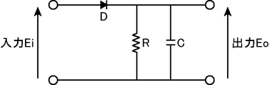
- FIG. 10 is a circuit diagram showing a configuration of an envelope detector in the Fourier transform spectrometer of the second embodiment.
- the Fourier transform spectrometer Db Similar to the Fourier transform spectrometer Da according to the first embodiment, the Fourier transform spectrometer Db according to the second embodiment measures the measured light to be measured with an interferometer, and integrates the measured measured light. This is a device for obtaining a spectrum of measured light by Fourier transforming an interferogram.
- the extraction unit 4111a when the extraction unit 4111a extracts the output of the predetermined range i from the output of the interferometer 11, the extraction unit 4111a extracts this according to the amplitude information of the vibration in the movable mirror 115.
- the Fourier transform spectrometer Db in the second embodiment further includes a center burst position detection unit that detects the position of the center burst in the interferogram, and the extraction unit 4111b includes the interferometer 11.
- the predetermined range i to be taken out is set using the center burst position detected by the center burst position detection unit as the amplitude information of the vibration in the movable mirror 115, and the interferometer 11.
- the output of the set predetermined range i is extracted from the output of.
- the Fourier transform spectrometer Db in the second embodiment includes an interferometer 11, a light receiving processing unit 20, a position detection processing unit 30b, a control calculation unit 41b, and an input.
- a unit 42 and an output unit 43 are provided.
- the interferometer 11, the light receiving processing unit 20, the input unit 42, and the output unit 43 in the Fourier transform spectrometer Db of the second embodiment are respectively connected to the interferometer 11 in the Fourier transform spectrometer Da of the first embodiment. Since it is the same as that of the light reception processing unit 20, the input unit 42, and the output unit 43, description thereof is omitted.
- the position detection processing unit 30b includes, for example, a position measurement light source 31b, a second light receiving unit 36, a zero-cross detection unit 37, and an envelope detection unit 38.
- the position detection processing unit 30b obtains the interference light of the laser light emitted from the position measurement light source 31b with the interferometer 11, as described with reference to FIG. 2 in the first embodiment.
- 32, a beam splitter 33, a beam splitter 34, and a condenser lens 35 are further provided. That is, the Fourier transform spectrometer Db of the second embodiment is provided with a position measurement light source 31b instead of the position measurement light source 31a with respect to the Fourier transform spectrometer Da of the first embodiment, and further includes an envelope detector. 38.
- the second light receiving unit 36, the zero cross detection unit 37, the collimator lens 32, the beam splitter 33, the beam splitter 34, and the condenser lens 35 in the Fourier transform spectrometer Db of the second embodiment are respectively the first embodiment. Since this is the same as the second light receiving unit 36, the zero cross detection unit 37, the collimator lens 32, the beam splitter 33, the beam splitter 34, and the condensing lens 35 in the Fourier transform spectrometer Da, the description thereof is omitted.
- the position measurement light source 31b is a light source device that emits laser light having a predetermined line width set in advance.
- the position measuring light source 31b includes, for example, a semiconductor laser that emits laser light having a predetermined line width. Further, for example, the position measuring light source 31b includes a laser device that emits monochromatic laser light, and a high-frequency superimposing device that superimposes the monochromatic laser light emitted from the laser device at a high frequency. A laser beam having a predetermined line width is emitted.
- the predetermined line width is a wavelength width (frequency width) such that the amplitude of the laser light obtained by the interferometer 11 changes in accordance with the movement of the movable mirror 115 of the interferometer 11. ).
- the magnitude of the amplitude of the laser beam in the interference light depends on the movement of the movable mirror 115 of the interferometer 11 as shown in FIG. 4 used in the description of the first embodiment. It does not change.
- Laser light having such a predetermined line width, and an example, as shown in FIG. 8, Gaussian profile relative to the central wave number 15151.52Cm -1 is a half-value width (FWHM) 2.3 cm -1 have.
- the laser light emitted from the position measuring light source 31 b is incident on the interferometer 11, and the interference light of the laser light is received by the second light receiving unit 36.
- the second light receiving unit 36 outputs an electrical signal corresponding to the light intensity of the interference light of the laser light to each of the zero cross detection unit 37 and the envelope detection unit 38.
- the envelope detector 38 is a circuit that detects an envelope of an electric signal input from the second light receiver 36 and corresponding to the light intensity of the interference light of the laser beam.
- the envelope detector 38 can employ various circuit configurations. For example, as shown in FIG. 10, the envelope detector 38 is connected in series with the diode D by being connected to the diode D and the cathode terminal of the diode D.
- the resistor element R is connected to the resistor element R, and the capacitor C is connected in parallel to the resistor element R. Both ends of the series-connected diode D and the resistor element R are input ends, and both ends of the resistor element R are The output end.
- the envelope detector 38 can detect the envelope with such a simple circuit configuration.
- the envelope detection unit 38 outputs an envelope of an electric signal corresponding to the detected light intensity of the interference light of the laser beam to the control calculation unit 41b.
- the control calculation unit 41b controls each part of the Fourier transform spectrometer Db according to the function of each part in order to obtain the spectrum of the light to be measured.
- the control calculation unit 41b functionally includes a spectrum calculation unit 411b and a center burst position calculation unit 412 by executing a program.
- the center burst position calculation unit 412 detects the position of the center burst in the interferogram. More specifically, in this embodiment, the center burst position calculation unit 412 detects a position that gives the maximum value of the envelope detected by the envelope detection unit 38 as the position of the center burst. As described above, in the present embodiment, the position of the center burst detects the envelope of the light intensity in the interference light of the laser light obtained by making the laser light having a predetermined line width enter the interferometer 11, It is obtained by detecting the position giving the maximum value of the detected envelope.
- the spectrum calculation unit 411b obtains the spectrum of the light to be measured by Fourier-transforming an integrated interferogram obtained by integrating a plurality of interferograms of the light to be measured generated by the interferometer 11. is there.
- the spectrum calculation unit 411b is functionally configured with an extraction unit 4111b, a search unit 4112, an integration unit 4113, and a calculation unit 4114 by executing a program. That is, the spectrum calculation unit 411b in the Fourier transform spectrometer Db of the second embodiment is different from the spectrum calculation unit 411a in the Fourier transform spectrometer Da of the first embodiment in that the extraction unit 4111b functions instead of the extraction unit 4111a. Constructed.
- the search unit 4112, the integration unit 4113, and the calculation unit 4114 of the spectrum calculation unit 411b in the Fourier transform spectrometer Db of the second embodiment are respectively the spectrum calculation unit 411b of the Fourier transform spectrometer Da of the first embodiment. Since the search unit 4112, the integration unit 4113, and the calculation unit 4114 are the same as those of the search unit 4112 of FIG.
- the extraction unit 4111 b When the output of the predetermined range i is extracted from the output of the interferometer 11, the extraction unit 4111 b performs center burst as amplitude information at the time of the reciprocation in the optical path difference forming optical element, in this embodiment, as vibration amplitude information in the movable mirror 115.
- the predetermined range i to be extracted is set using the position of the center burst detected by the position calculation unit 412, and the output of the set predetermined range i is extracted from the output of the interferometer 11.
- the extraction unit 4111 b extracts the predetermined range extracted this time with respect to the predetermined range extracted in the first measurement.
- the predetermined range i to be extracted this time is set by matching the center position of the predetermined range i with the position of the center burst obtained by the center burst position calculation unit 412, and this setting is made from the output of the interferometer 11.
- the output of the predetermined range i is taken out.
- FIG. 11 is a diagram (No. 1) for describing a predetermined range to be taken out by the takeout unit in the second embodiment.
- FIG. 12 is a diagram (No. 2) for explaining a predetermined range to be taken out by the take-out unit in the second embodiment.
- FIGS. 11A and 12A show measurement results (outputs of the AD conversion unit 23) in the first measurement and the n-th measurement (n is an integer of 2 or more), respectively
- FIG. FIG. 12B and FIG. 12B show envelopes (outputs of the envelope detector 38) in the first and n-th measurements (n is an integer of 2 or more), respectively.
- the Fourier transform spectrometer Db takes in the measurement light emitted from the measurement object SM.
- the measured light is incident on the interferometer 11b and is received by the first light receiving unit 21 as interference light of the measured light, as in the case of the interferometer 11 of the Fourier transform spectrometer Da of the first embodiment.
- the electric signal is amplified by the amplification unit 22 and output to the AD conversion unit 23.
- the Fourier transform spectrometer Db also captures laser light having a predetermined half width emitted from the position measuring light source 31b.
- This laser light is incident on the interferometer 11b through the beam splitter 33, interferes with the interferometer 11b in the same manner as described above, and is received by the second light receiving unit 36 through the beam splitter 34 as interference light of the laser light. Is done.
- the second light receiving unit 36 photoelectrically converts the incident interference light of the laser beam and outputs the output electric signal to the zero cross detection unit 37 and the envelope detection unit 38, respectively.
- the zero cross detector 37 detects the zero cross timing of the electrical signal and outputs it to the AD converter 23. While such measured light and laser light are respectively taken into the interferometer 11b, the movable mirror 115 of the interferometer 11b is moved along the optical axis direction under the control of the control calculation unit 41b.
- the AD conversion unit 23 samples the electric signal from the amplification unit 22 at the zero cross timing from the zero cross detection unit 37 and performs AD conversion from an analog signal to a digital signal.
- the AD conversion unit 23 controls the electric signal of the AD converted digital signal. It outputs to the spectrum calculating part 411b of the calculating part 41b.
- an interferogram as shown in FIGS. 11A and 12A is input from the AD conversion unit 23 to the spectrum calculation unit 411b of the control calculation unit 41b.
- the envelope detection unit 38 an electric signal (output of the second light receiving unit 36) based on the interference light of the laser beam having the predetermined line width is subjected to envelope detection, and FIG. 11 (B) and FIG. ) Is input from the envelope detector 38 to the center burst position calculator 412 of the control calculator 41b.
- the envelope of the light intensity in the interference light of the laser light having the predetermined line width is the same as in the case of the monochromatic laser light in the zero cross timing, but the amplitude is the largest at the position of the optical path difference 0, and the sideband It has a profile in which the amplitude gradually decreases as it approaches the position.
- the envelope of the light intensity reaches a maximum value at the center burst position. Therefore, the position of the center burst can be detected by detecting the envelope of the light intensity in the interference light of the laser light having a predetermined line width.
- the center burst position calculation unit 412 detects the maximum value of the envelope input from the envelope detection unit 38, and obtains the position giving this maximum value as the position of the center burst. Then, the center burst position calculation unit 412 outputs the obtained center burst position to the extraction unit 4111b.
- the interferogram of the light to be measured is input from the AD conversion unit 23 and the position of the center burst is input from the center burst position calculation unit 412 to the extraction unit 4111b.
- the extraction unit 4111b is center information as amplitude information when the optical path difference forming optical element is reciprocated, that is, amplitude information of vibration in the movable mirror 115 in this embodiment.
- the predetermined range i to be extracted is set using the position of the center burst detected by the burst position calculation unit 412, and the output of the set predetermined range i is extracted from the output of the interferometer 11.
- the extraction unit 4111b extracts the output of the predetermined range i from the output of the interferometer 11, while expanding the predetermined range i extracted this time with respect to the predetermined range extracted in the first measurement, A predetermined range i is set around the center burst position, and the output of the set predetermined range i is extracted from the output of the interferometer 11.
- the predetermined range i is expressed by Equation 12 (see FIGS. 11A and 11B), and the nth time In the measurement, the predetermined range i is expressed by the following expression 13 (see FIGS. 12A and 12B).
- the search unit 4112 finds measurement data having the same optical path difference in each measurement data set extracted by the extraction unit 4111b. For example, as in the first embodiment, the search unit 4112 obtains the maximum value of the cross-correlation, obtains the minimum value in the sum of the squares of the differences about the measurement points, or about the measurement points. The measurement data of the same optical path difference is found by obtaining the minimum value in the sum of the absolute values of the differences.
- the following equation 14 when obtaining the maximum value of the cross-correlation, the following equation 14 is used, and when obtaining the minimum value in the sum of the squares of the differences for the measurement points, the following equation 15 is obtained.
- the minimum value in the sum of the absolute values of the differences for the measurement point is used, the following equation 16 is used.
- the width of the range from which data is extracted (the width from the start position to the end position of the extraction range) is widened or narrowed according to the position I (n) that gives the maximum value of the envelope. It may be changed by doing. For example, when I (n) ⁇ I (1), in the n-th measurement data set Interferogram n (i), the number of points represented by the following expression 17-2 in the range represented by the following expression 17-1 When data is extracted and I (n) ⁇ I (1), in the nth measurement data set Interferogram n (i), it is expressed by the following expression 17-4 in the range expressed by the following expression 17-3. Data is retrieved.
- the integration unit 4113 uses the same optical path found by the search unit 4112 in each measurement data set extracted by the extraction unit 4111b.
- An integrated interferogram is generated by adding the difference measurement data together.
- the calculation unit 4114 obtains the spectrum of the light to be measured by Fourier transforming the generated integrated interferogram according to the above formulas 9 and 10. The obtained spectrum of the light to be measured is output to the output unit 43.
- the position of the center burst is detected by the envelope detector 38 and the center burst position calculator 412.
- this detected center burst is used as amplitude information at the time of the reciprocation in the optical path difference forming optical element, that is, vibration amplitude information in the movable mirror 115 in this embodiment.
- the predetermined range i to be taken out is set according to the detected center burst position.
- the position of the center burst varies due to the amplitude variation, but the position of the center burst is actually detected and the predetermined range i is set. Therefore, measurement data in a range including the center burst can be surely taken out, and accordingly, a plurality of interferograms can be integrated more suitably.
- the Fourier transform spectrometer Db of the second embodiment detects the position of the center burst by detecting the envelope of the light intensity in the interference light of the laser light having a predetermined line width, for example, FIG.
- the detector circuit can be configured with a simpler circuit configuration as shown in FIG.
- the Fourier transform spectrometer Db of the second embodiment is configured such that the laser beam is a laser beam having a predetermined line width, and detects the position of the movable mirror 115 as a configuration for detecting the position of the center burst. A part of the structure is diverted. More specifically, the configuration from the position measurement light source 31 b to the second light receiving unit 36 is shared, and the output of the second light receiving unit 36 is output to each of the zero cross detection unit 37 and the envelope detection unit 38. For this reason, the Fourier transform spectrometer Db of the second embodiment can detect the position of the center burst with a smaller circuit configuration.
- the position measurement light source 31b a laser device that emits laser light having a predetermined line width by superimposing monochromatic laser light at high frequency, or a predetermined line A semiconductor laser that emits laser light having a width is used. For this reason, in the second embodiment, a position measurement light source 31b that emits laser light having the predetermined line width can be configured more simply.
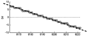
- FIG. 13 is a diagram for explaining a second mode method for obtaining the position of the center burst based on the envelope in the interference light of the laser beam.
- FIG. 13A shows the envelope
- FIG. 13B shows a differential waveform of the envelope.
- FIG. 14 is a diagram for explaining the method of the third aspect for obtaining the position of the center burst based on the envelope in the interference light of the laser light.
- the horizontal axis of FIGS. 13 and 14 indicates the optical path difference (position of the moving mirror 115), and these vertical axes indicate the levels.
- the center burst position calculation unit 412 calculates the maximum value of the envelope input from the envelope detection unit 38 according to the movement of the movable mirror 115 (change in optical path difference).
- the detection may be performed at a point where the amplitude value (level) has changed from increase to decrease.
- FIG. 13A when the envelope is in the vicinity of the maximum value, the movement of the movable mirror 115 (optical path difference). If the point changes relatively slowly according to the change of the above, it is not easy to detect the point with high accuracy.
- the center burst position calculation unit 412 determines the position that gives the maximum value of the envelope detected by the envelope detection unit 38 based on the difference information of the envelope detected by the envelope detection unit 38 as the position of the center burst. You may detect as.
- the center burst position calculation unit 412 obtains a difference between two points on the envelope at an appropriate interval. For example, when the difference between two points on the envelope is obtained with respect to the envelope shown in FIG. 13A, the difference graph shown in FIG. 13B is obtained as the difference information. In the difference graph, since the zero cross point at which the difference value changes from a positive value to a negative value corresponds to the position where the maximum value is given, the center burst position calculation unit 412 determines that the difference value is from the positive value in the difference graph. A zero cross point that turns to a negative value is obtained, and the zero cross point may be set as the center burst position.
- the larger the interval for obtaining the difference the larger the difference value, and the zero cross point can be detected with higher accuracy.
- the position of the center burst can be detected with higher accuracy.
- the storage capacity of the storage element that stores the measurement result of the envelope is restricted, and the interval cannot be made too large, or the number of bits Z of the AD conversion unit 23 is small and the resolution is small.
- the difference may have a stepped shape near the zero cross point as shown in FIG. In such a case, the position of the center burst may be obtained by linearly approximating the difference graph near the zero cross point by the least square method and obtaining the zero cross point of the approximate straight line.
- the center burst position calculation unit 412 in the Fourier transform spectrometer Db of the second embodiment can more accurately detect the position that gives the maximum value of the envelope. Even if it is difficult to distinguish the maximum value of the envelope because the change of the envelope is gentle, it is possible to detect the position where the maximum value of the envelope is given.
- a Fourier transform spectrometer includes a plurality of optical elements that receive measurement light to be measured and form two optical paths between an incident position of the measurement light and an interference position,
- the plurality of optical elements include an interferometer including an optical path difference forming optical element that causes an optical path difference between the two optical paths by moving in the optical axis direction, and the light to be measured generated by the interferometer.
- a spectrum calculation unit that obtains a spectrum of the measured light by performing a Fourier transform on an integrated interferogram obtained by integrating a plurality of interferograms of the optical path difference forming optical element, In order to generate a plurality of interferograms of the interferogram, reciprocates twice or more in the optical axis direction, and the spectrum calculation unit takes out a predetermined range of output from the output of the interferometer A predetermined range to be extracted is set according to amplitude information at the time of the reciprocation in the optical path difference forming optical element, and an extraction unit for extracting the output of the predetermined range from the output of the interferometer; In order to integrate a plurality of interferograms, a search unit for finding measurement data of the same optical path difference at each output in each predetermined range extracted by the extraction unit, and a plurality of interferograms of the measured light Therefore, in each output of each predetermined range extracted by the extraction unit, an integration unit that generates the integrated interferogram by adding together measurement data of the same optical path difference found
- the Fourier transform spectroscopic method includes a plurality of optical elements that receive light to be measured to be measured and form two optical paths between an incident position of the light to be measured and an interference position.
- the plurality of optical elements includes an optical path difference forming optical element that generates an optical path difference between the two optical paths by moving in the optical axis direction, and the interferometer generated by the interferometer
- a spectrum calculation unit that obtains a spectrum of the measured light by Fourier transforming an integrated interferogram obtained by integrating a plurality of interferograms of the measured light, and the optical path difference forming optical element comprises: In order to generate a plurality of interferograms of the light to be measured, a Fourier transform spectroscopic method used in a Fourier transform spectrometer that reciprocates twice or more in the optical axis direction.
- the predetermined range to be extracted according to the amplitude information at the time of the reciprocation in the optical path difference forming optical element is An extraction step of setting and extracting the output of the set predetermined range from the output of the interferometer, and each of the predetermined ranges extracted in the extraction step to integrate a plurality of interferograms of the measured light
- the product is the integrated interferogram was and a calculation step of obtaining a spectrum of the light to be measured by Fourier transform.
- the predetermined range to be extracted is the amplitude when the optical path difference forming optical element is reciprocated.
- the Fourier transform spectrometer and the Fourier transform spectroscopic method having such a configuration since amplitude information at the time of reciprocation in the optical path difference forming optical element is taken into account, measurement data in a range including an interferogram is more obtained. Therefore, it is possible to appropriately extract a plurality of interferograms.
- the amplitude information used in the extraction unit is obtained by calculating the center position of the reciprocation in the first measurement and the center position of the reciprocation in the current measurement. This is the amount of deviation.
- the Fourier transform spectrometer having such a configuration a deviation amount between the reciprocal center position in the first measurement and the reciprocal center position in the current measurement is used as the amplitude information. For this reason, the Fourier transform spectrometer having such a configuration can suitably cope with a case where the optical path difference forming optical element is shifted left-right symmetrically, and more appropriately extracts measurement data in a range including the interferogram. Therefore, a plurality of interferograms can be preferably integrated.
- the Fourier transform spectrometer described above further includes a center burst position detection unit that detects a position of the center burst in the interferogram, and the extraction unit has a predetermined range from the output of the interferometer.
- the predetermined range to be taken out is set using the position of the center burst detected by the center burst position detecting unit as amplitude information at the time of the reciprocation in the optical path difference forming optical element, and the interferometer The output of the set predetermined range is taken out from the output.
- the Fourier transform spectrometer having such a configuration In the Fourier transform spectrometer having such a configuration, the position of the center burst is detected by the center burst position detector. For this reason, the Fourier transform spectrometer having such a configuration can reliably extract measurement data in a range including the center burst, and can more preferably integrate a plurality of interferograms.
- the center burst position detection unit may interfere with the laser light obtained by causing laser light having a predetermined line width to enter the interferometer. An envelope of light intensity in the light is detected, and a position giving the maximum value of the detected envelope is detected as the position of the center burst.
- the Fourier transform spectrometer Since the Fourier transform spectrometer having such a configuration detects the position of the center burst by detecting the envelope of the light intensity in the interference light of the laser beam having a predetermined line width, it has a simpler circuit configuration.
- a detection circuit can be configured.
- the interference light of the laser beam is used to detect the position of the movable mirror, and the zero cross timing in the interference light of the laser beam is set as the sampling timing.
- a part of the configuration for detecting the position of the movable mirror is obtained by using the laser beam as the laser beam having the predetermined line width of the position measurement light source. It can also be used as a part of the configuration for detecting the position of the center burst. For this reason, the Fourier transform spectrometer having the above configuration can detect the position of the center burst with a smaller circuit configuration.
- the position measurement light source is a laser device that emits laser light having the predetermined line width by superimposing monochromatic laser light at high frequency.
- a position measurement light source that emits laser light having the predetermined line width is configured more simply.
- the position measurement light source is a semiconductor laser that emits laser light having the predetermined line width.
- a position measurement light source that emits laser light having the predetermined line width is configured more simply.
- the center burst position detection unit is detected by the envelope detection unit based on difference information of the envelope detected by the envelope detection unit. A position that gives the maximum value of the envelope is detected as the position of the center burst.
- the Fourier transform spectrometer having such a configuration can detect the position where the maximum value of the envelope is given more accurately, and since the change of the envelope is gentle, the maximum value of the envelope is Even if it is difficult to distinguish, it is possible to detect the position that gives the maximum value of the envelope.
- the search unit outputs a predetermined range of outputs extracted by the extraction unit in the first measurement and the nth (n is an integer of 2 or more). In this measurement, the maximum value of the cross-correlation is obtained with respect to the output within the predetermined range extracted by the extraction unit, and measurement data having the same optical path difference is found.
- the Fourier transform spectrometer having such a configuration can preferably integrate a plurality of interferograms.
- the search unit outputs a predetermined range of outputs extracted by the extraction unit in the first measurement and the nth (n is an integer of 2 or more).
- the measurement data of the same optical path difference is found by obtaining the minimum value in the sum of the squares of the differences at the measurement points with respect to the output in the predetermined range taken out by the take-out unit in the above measurement.
- the Fourier transform spectrometer having such a configuration can preferably integrate a plurality of interferograms.
- the search unit outputs a predetermined range of outputs extracted by the extraction unit in the first measurement and the nth (n is an integer of 2 or more).
- the measurement data of the same optical path difference is found by obtaining the minimum value in the sum of the absolute values of the differences at the measurement points with respect to the output in the predetermined range extracted by the extraction unit in the measurement.
- the measurement data of the same optical path difference is found by the sum of the absolute values of the differences. Therefore, the measurement data of the same optical path difference can be found by simpler information processing.
- a Fourier transform spectrometer and a Fourier transform spectrometer can be provided.
Landscapes
- Physics & Mathematics (AREA)
- Spectroscopy & Molecular Physics (AREA)
- General Physics & Mathematics (AREA)
- Spectrometry And Color Measurement (AREA)
Abstract
La présente invention concerne un spectromètre à transformée de Fourier (Da) comprenant : un interféromètre (11) qui produit une différence de trajet optique entre deux trajets optiques au moyen de vibrations ; et une unité de calcul de spectre (411a) qui détermine le spectre de lumière à mesurer en soumettant à une transformée de Fourier un interférogramme cumulé obtenu par l'addition d'une pluralité d'interférogrammes générés par l'interféromètre (11). Quand l'unité de calcul de spectre (411a) extrait un ensemble prédéterminé de résultats provenant de l'interféromètre (11), elle fixe l'ensemble prédéterminé en fonction d'informations d'amplitude associées aux vibrations et extrait l'ensemble prédéterminé de résultats dans les résultats provenant de l'interféromètre (11).
Priority Applications (1)
| Application Number | Priority Date | Filing Date | Title |
|---|---|---|---|
| JP2013517823A JP5846202B2 (ja) | 2011-05-31 | 2012-04-13 | フーリエ変換型分光計およびフーリエ変換型分光方法 |
Applications Claiming Priority (2)
| Application Number | Priority Date | Filing Date | Title |
|---|---|---|---|
| JP2011122352 | 2011-05-31 | ||
| JP2011-122352 | 2011-05-31 |
Publications (1)
| Publication Number | Publication Date |
|---|---|
| WO2012164810A1 true WO2012164810A1 (fr) | 2012-12-06 |
Family
ID=47258688
Family Applications (1)
| Application Number | Title | Priority Date | Filing Date |
|---|---|---|---|
| PCT/JP2012/002577 Ceased WO2012164810A1 (fr) | 2011-05-31 | 2012-04-13 | Spectromètre à transformée de fourier et procédé de spectroscopie à transformée de fourier |
Country Status (2)
| Country | Link |
|---|---|
| JP (1) | JP5846202B2 (fr) |
| WO (1) | WO2012164810A1 (fr) |
Cited By (2)
| Publication number | Priority date | Publication date | Assignee | Title |
|---|---|---|---|---|
| WO2013179572A1 (fr) * | 2012-05-29 | 2013-12-05 | コニカミノルタ株式会社 | Spectromètre à transformée de fourier et procédé spectroscopique à transformée de fourier |
| WO2019009401A1 (fr) * | 2017-07-06 | 2019-01-10 | 浜松ホトニクス株式会社 | Module optique |
Citations (4)
| Publication number | Priority date | Publication date | Assignee | Title |
|---|---|---|---|---|
| JPS6238324A (ja) * | 1985-08-12 | 1987-02-19 | Shimadzu Corp | フ−リエ変換型分光光度計 |
| JPH1090065A (ja) * | 1996-09-11 | 1998-04-10 | Kurabo Ind Ltd | フーリエ変換分光器のデータ処理方法及びデータ処理装置 |
| JP2008134133A (ja) * | 2006-11-28 | 2008-06-12 | Shimadzu Corp | フーリエ変換型赤外分光光度計 |
| JP2011080854A (ja) * | 2009-10-07 | 2011-04-21 | Konica Minolta Holdings Inc | フーリエ変換分光器 |
Family Cites Families (2)
| Publication number | Priority date | Publication date | Assignee | Title |
|---|---|---|---|---|
| JP3497927B2 (ja) * | 1995-07-13 | 2004-02-16 | 日本分光株式会社 | インターフェログラム積算装置 |
| AT413765B (de) * | 2004-06-24 | 2006-05-15 | Ctr Carinthian Tech Res Ag | Anordnung zum aufbau eines miniaturisierten fourier-transform-interferometers für optische strahlung nach dem michelson- bzw. einem daraus abgeleiteten prinzip |
-
2012
- 2012-04-13 WO PCT/JP2012/002577 patent/WO2012164810A1/fr not_active Ceased
- 2012-04-13 JP JP2013517823A patent/JP5846202B2/ja not_active Expired - Fee Related
Patent Citations (4)
| Publication number | Priority date | Publication date | Assignee | Title |
|---|---|---|---|---|
| JPS6238324A (ja) * | 1985-08-12 | 1987-02-19 | Shimadzu Corp | フ−リエ変換型分光光度計 |
| JPH1090065A (ja) * | 1996-09-11 | 1998-04-10 | Kurabo Ind Ltd | フーリエ変換分光器のデータ処理方法及びデータ処理装置 |
| JP2008134133A (ja) * | 2006-11-28 | 2008-06-12 | Shimadzu Corp | フーリエ変換型赤外分光光度計 |
| JP2011080854A (ja) * | 2009-10-07 | 2011-04-21 | Konica Minolta Holdings Inc | フーリエ変換分光器 |
Cited By (20)
| Publication number | Priority date | Publication date | Assignee | Title |
|---|---|---|---|---|
| WO2013179572A1 (fr) * | 2012-05-29 | 2013-12-05 | コニカミノルタ株式会社 | Spectromètre à transformée de fourier et procédé spectroscopique à transformée de fourier |
| JPWO2013179572A1 (ja) * | 2012-05-29 | 2016-01-18 | コニカミノルタ株式会社 | フーリエ変換型分光計およびフーリエ変換型分光方法 |
| WO2019009401A1 (fr) * | 2017-07-06 | 2019-01-10 | 浜松ホトニクス株式会社 | Module optique |
| WO2019009404A1 (fr) * | 2017-07-06 | 2019-01-10 | 浜松ホトニクス株式会社 | Module optique |
| JP6496463B1 (ja) * | 2017-07-06 | 2019-04-03 | 浜松ホトニクス株式会社 | 光モジュール |
| CN110799817A (zh) * | 2017-07-06 | 2020-02-14 | 浜松光子学株式会社 | 光学组件 |
| JPWO2019009401A1 (ja) * | 2017-07-06 | 2020-04-30 | 浜松ホトニクス株式会社 | 光モジュール |
| EP3650820A4 (fr) * | 2017-07-06 | 2021-04-21 | Hamamatsu Photonics K.K. | Module optique |
| US11054309B2 (en) | 2017-07-06 | 2021-07-06 | Hamamatsu Photonics K.K. | Optical module |
| US11067380B2 (en) | 2017-07-06 | 2021-07-20 | Hamamatsu Photonics K.K. | Optical module |
| US11187579B2 (en) | 2017-07-06 | 2021-11-30 | Hamamatsu Photonics K.K. | Optical device |
| US11209260B2 (en) | 2017-07-06 | 2021-12-28 | Hamamatsu Photonics K.K. | Optical module having high-accuracy spectral analysis |
| JP7233365B2 (ja) | 2017-07-06 | 2023-03-06 | 浜松ホトニクス株式会社 | 光モジュール |
| US11624605B2 (en) | 2017-07-06 | 2023-04-11 | Hamamatsu Photonics K.K. | Mirror unit and optical module |
| US11629946B2 (en) | 2017-07-06 | 2023-04-18 | Hamamatsu Photonics K.K. | Mirror unit and optical module |
| US11629947B2 (en) | 2017-07-06 | 2023-04-18 | Hamamatsu Photonics K.K. | Optical device |
| US11635290B2 (en) | 2017-07-06 | 2023-04-25 | Hamamatsu Photonics K.K. | Optical module |
| US11879731B2 (en) | 2017-07-06 | 2024-01-23 | Hamamatsu Photonics K.K. | Mirror unit and optical module |
| US12152878B2 (en) | 2017-07-06 | 2024-11-26 | Hamamatsu Photonics K.K. | Mirror unit and optical module |
| US12298132B2 (en) | 2017-07-06 | 2025-05-13 | Hamamatsu Photonics K.K. | Optical device |
Also Published As
| Publication number | Publication date |
|---|---|
| JPWO2012164810A1 (ja) | 2014-07-31 |
| JP5846202B2 (ja) | 2016-01-20 |
Similar Documents
| Publication | Publication Date | Title |
|---|---|---|
| JP5725165B2 (ja) | フーリエ変換型分光計およびフーリエ変換型分光方法 | |
| US8203715B2 (en) | Knowledge based spectrometer | |
| CN113677951B (zh) | 光距离测定装置 | |
| EP3370047A1 (fr) | Dispositif de mesure de spectre, dispositif spectroscopique et système spectroscopique | |
| CN114894308B (zh) | 一种基于低相干干涉的光谱仪标定方法与系统 | |
| KR20210049679A (ko) | 광학 측정 장치, 파장 교정 방법 및 표준 시료 | |
| JP5846202B2 (ja) | フーリエ変換型分光計およびフーリエ変換型分光方法 | |
| RU2569052C1 (ru) | Способ компенсации дрейфа частоты в интерферометре | |
| JP5835101B2 (ja) | フーリエ変換型分光計およびフーリエ変換型分光方法ならびにフーリエ変換型分光計用アタッチメント | |
| JP5974929B2 (ja) | 迷光補正方法、及びこれを用いたフーリエ変換型分光装置 | |
| JP5891955B2 (ja) | フーリエ変換型分光計用タイミング生成装置および該生成方法ならびにフーリエ変換型分光計および該分光方法 | |
| JP5915737B2 (ja) | フーリエ変換型分光計およびフーリエ変換型分光方法 | |
| US10365159B2 (en) | Spectrometer system and a method for compensating for time periodic perturbations of an interferogram generated by the spectrometer system | |
| JP5737386B2 (ja) | フーリエ変換型分光計およびフーリエ変換型分光方法 | |
| JP2014013185A (ja) | 分光撮像装置調整方法および分光撮像システム | |
| JP2014002068A (ja) | 厚みモニタリング装置、エッチング深さモニタリング装置および厚みモニタリング方法 | |
| WO2014199888A1 (fr) | Spectromètre à transformée de fourier et spectroscopie par transformée de fourier ainsi que dispositif générateur de cadencement de spectromètre à transformée de fourier | |
| US11703461B2 (en) | Optical sensor for surface inspection and metrology | |
| JP2014137328A (ja) | フーリエ変換型分光計およびフーリエ変換型分光計の波長校正方法 | |
| JP2014228281A (ja) | フーリエ変換型分光計およびフーリエ変換型分光計の校正方法 | |
| US11561080B2 (en) | Optical sensor for surface inspection and metrology | |
| CN121026197B (zh) | 一种基于自适应局部光谱匹配法的光频域反射解调方法、装置及传感系统 | |
| JP2006300664A (ja) | フーリエ分光装置,測定タイミング検出方法 | |
| JP2002296012A (ja) | 膜厚測定方法及び膜厚測定装置 | |
| Kim et al. | A monolithic MEMS michelson interferometer for ftir spectroscopy |
Legal Events
| Date | Code | Title | Description |
|---|---|---|---|
| 121 | Ep: the epo has been informed by wipo that ep was designated in this application |
Ref document number: 12792262 Country of ref document: EP Kind code of ref document: A1 |
|
| ENP | Entry into the national phase |
Ref document number: 2013517823 Country of ref document: JP Kind code of ref document: A |
|
| NENP | Non-entry into the national phase |
Ref country code: DE |
|
| 122 | Ep: pct application non-entry in european phase |
Ref document number: 12792262 Country of ref document: EP Kind code of ref document: A1 |