WO2012165209A1 - Porte-lentilles de contact - Google Patents
Porte-lentilles de contact Download PDFInfo
- Publication number
- WO2012165209A1 WO2012165209A1 PCT/JP2012/062984 JP2012062984W WO2012165209A1 WO 2012165209 A1 WO2012165209 A1 WO 2012165209A1 JP 2012062984 W JP2012062984 W JP 2012062984W WO 2012165209 A1 WO2012165209 A1 WO 2012165209A1
- Authority
- WO
- WIPO (PCT)
- Prior art keywords
- lens
- storage
- holder
- contact lens
- lens holder
- Prior art date
- Legal status (The legal status is an assumption and is not a legal conclusion. Google has not performed a legal analysis and makes no representation as to the accuracy of the status listed.)
- Ceased
Links
Images




Classifications
-
- A—HUMAN NECESSITIES
- A45—HAND OR TRAVELLING ARTICLES
- A45C—PURSES; LUGGAGE; HAND CARRIED BAGS
- A45C11/00—Receptacles for purposes not provided for in groups A45C1/00-A45C9/00
- A45C11/005—Contact lens cases
Definitions
- the present invention relates to a contact lens holder having a novel structure, and in particular, it is easy to take out a contact lens and can be stably stored, the handling of the entire equipment is simple, and the manufacturing cost is reduced. It is about.
- the lens is a highly controlled medical device for correcting vision, it is placed directly on the cornea, so it is very important to store it safely and stably.
- the container and the holder follow the lens mainly, there is a situation in which development and manufacturing costs are not so much applied to the subordinate.
- a lens holder made of a single molded body (Patent Document 1) for the purpose of reducing manufacturing costs.
- a lens housing portion is formed in a mesh shape in order to make contact when disinfecting with the hydrogen peroxide solution in the container.
- it has a separating part so as to hold the pair of lenses separately, and the separating part is also provided with a mesh.
- This lens holder is formed by forming two basket portions that can be bent at the separation portion and cover the respective surfaces of the separation portion.
- a container (Patent Document 2) characterized by venting gas generated during decomposition of hydrogen peroxide and delaying the introduction of the neutralizing agent are delayed.
- Patent Document 3 a container that can surely perform disinfection and the like. Both of them use a conventionally known lens holder, and there are separate problems to be solved. The former is how the generated gas is discharged from the container, and the latter is in the time difference between disinfection and neutralization.
- the holders described in these documents are for taking out or storing the lenses one by one, and it is necessary to open and close the holder at least twice for wearing.
- Patent Document 4 Patent Document 5
- Patent Document 6 Patent Document 6
- the lens can be sealed simply by assembling the container without this film bonding process, the (bonding) process management becomes unnecessary.
- these containers are formed entirely of resin instead of using a film, the container can be used repeatedly as a user. Then, although it is a disposable lens, there is a possibility that the lens after use is stored and worn again, or the container is contaminated with microorganisms and the like so that hygiene management becomes insufficient. Preventing such a situation has become a new problem, and each of the above-described containers has been made to solve the problem. This is because the container and the lens can be periodically discarded if resealing is disabled.
- JP-A-6-51249 JP-A-9-103470 Special Table 2002-532151 JP 2002-306227 A JP 2004-121645 A Japanese Patent Laid-Open No. 2005-121907 JP-A-6-296514
- An object of the present invention is to provide a holder having a structure in which a lens can be easily taken out from a lens storage state that has not been sufficiently considered in the above-described prior art. It is a matter of course to stably hold the lens, and to provide a lens holder that can simplify the handling of the holder and can further reduce the manufacturing cost.
- the present invention includes a pair of left and right storage units that individually store lenses, a pair of left and right cover units that cover each storage unit, a foldable first connecting portion that connects each storage unit, and each cover unit.
- a foldable second connecting portion that connects, a foldable third connecting portion that connects the left storage portion and the left cover portion, and a foldable fourth connecting portion that connects the right storage portion and the right cover portion; ,
- a lens holder A lens holder.
- the virtual straight lines that bisect each of the first to fourth connecting portions in the opening direction are respectively extended, and when the virtual straight lines are projected on the same plane, the figure connecting the intersections of the virtual straight lines Form a trapezoidal shape, with the imaginary straight line of the first connecting part as the lower base, the imaginary straight line of the second connecting part as the upper base, the virtual lines of the third connecting part and the fourth connecting part as hypotenuses, and the length of the lower base Are connected so as to be longer than the length of the upper base.
- the lens holder of the present invention has two lens storage portions and two cover portions covering the lens storage portions, and the storage portions and the cover portions are connected to each other and moved in cooperation with each other. In this way, the two lenses can be taken out (opened state).
- the cover portions overlap each other to isolate the two lenses.
- the overlapping of the cover part is released in accordance with the movement of the storage part, and the cover part is opened in a so-called pop-up manner due to the projection of the virtual straight line forming a trapezoid.
- the trapezoid formed by the virtual straight line is an isosceles trapezoid. This is because the balance of the entire holder is good both in the lens holding state and in the open state, and the movement of the cover is smooth and symmetrical. Further, when the lens is stored or taken out, there is an effect that the lens is not damaged and is easy to handle.
- the first, third and fourth connecting parts are bent in the valley folding direction, and the second connecting part is bent in the mountain folding direction, so that the contact lens is held in each storage part. .
- each of these bending operations proceeds almost simultaneously.
- the lens can be held or taken out with a single operation in order to move in the reverse direction.
- each cover may have at least one through hole.
- This through hole is preferably formed so as to connect the lens storage spaces formed by the respective lens storage portions and the cover portions in a state where the lens is held and the cover portions are overlapped. This is because such a through-hole can absorb a partial pressure change in the entire storage portion by eliminating a pressure difference between the left and right lens storage spaces.
- a handle may be provided on one of the left and right storage parts, and a fixing part with another part may be provided on the other side.
- a container for storing the holder there are a container for storing the holder and a lid for sealing the storage container.
- the lens holder of the present invention can be formed of a single molded body. This is because manufacturing costs are reduced and mass production is easy.
- the storage portion and the cover portion are connected in an annular shape by the connecting portions, and since each cover portion is connected, the lens can be taken in and out in one operation. Operability is improved. Moreover, since these structures can be folded, they can be compactly assembled as a whole, and are excellent in storage and carrying. Further, when the cover is opened from the folded state, the cover is opened in a so-called pop-up manner, and the left and right storage parts are opened in the same direction, so that the lens can be easily taken out and stored.
- the lens holder can be made into a single molded body by a method such as injection molding using resin or the like, so that stable quality can be maintained and mass production can be achieved, which contributes to cost reduction.
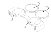
- FIG. 1 is a diagram illustrating a state in which virtual lines are projected on the same plane according to an example of the present invention.
- FIG. 2 is a view showing an example of the holder of the present invention in which the cover is flat and the storage is concave.
- FIG. 3 is a view showing an example of the holder of the present invention in which the cover portion is a flat surface and the storage portion is convex.
- FIG. 4 is a diagram illustrating a state in which an example of another container and an example of the present invention are combined.
- FIG. 4 (I) is an opened state of the holder
- FIG. FIG. 4 (III) is a top view
- FIG. 4 (IV) is a cross-sectional view along the line AA.
- FIG. 5 is a diagram for explaining a state in which the entire holder according to the present invention is accommodated in another container.
- FIG. 5 (I) is an open state of the holder, and
- FIG. 5 (II) is a holder folded.
- FIG. 5 (III) is a diagram showing a state in which the entire holder is accommodated in another container.
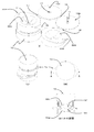
- FIG. 6 is an explanatory diagram showing a process of shifting from a state in which the lens is housed to a state in which it can be taken out.
- FIG. 7 is a view showing another aspect of the engaging portion.
- FIG. 8 is a view showing another embodiment of the holder of the present invention.
- FIG. 9 is a diagram for explaining the names of the parts studied in the example.
- the present invention relates to a lens holder that opens in such a way that it pops up when a book (a so-called pop-out picture book) is opened.
- the lens can be easily removed by a single opening operation. It is a holding tool.
- Conventional lens holders require one operation for each lens to be taken out, that is, at least twice for wearing the lens in both eyes. This is a significant difference from the prior art.
- description will be given based on the accompanying drawings.
- the lens holder of the present invention has a pair of left and right storage parts (2A, 2B) for individually storing lenses, and a pair of left and right cover parts (3C, 3D) for covering each storage part. ), A foldable first connecting portion (5) connecting the storage portions, a foldable second connecting portion (6) connecting the cover portions, and connecting the left storage portion and the left cover portion. It is a contact lens holder (1) composed of a bendable third connecting part (7) and a bendable fourth connecting part (8) connecting the right storage part and the right cover part.
- the virtual straight line (5L) of the first connecting part is the lower base
- the virtual straight line (6L) of the second connecting part is the upper base
- each virtual straight line of the third connecting part and the fourth connecting part (7L, 8L) is a hypotenuse
- the length of the lower base is connected so as to be longer than the length of the upper base.
- the two-dot chain line described in the storage part and the cover part shown in the drawing is shown to indicate that it is a curved surface, has no other special meaning, and is the same in other drawings. .
- the surface of the storage part (2A, 2B) is smooth so as not to damage the lens, and preferably close to the curvature on the side where the lens to be stored comes into contact.
- the lens is usually stored with the convex surface down, and the surface of the storage portion is correspondingly concave (see FIGS. 1 and 2). If the lens concave surface is to be stored, the storage portion is preferably convex (see FIG. 3). This is to prevent an unnecessary load from being applied to the lens being stored. For the same reason, the curvature of the storage section is set close to the curvature of the lens.
- the surface that the fingertip touches when taking out is basically only on the outer surface side of the lens.
- the inner surface side of the lens comes into contact with the cornea. Therefore, in terms of dirt and hygiene, it is preferable that the inner surface side should not be brought into contact with the fingertip as much as possible. Therefore, in this sense, there is an effect of making it convex.
- a soft contact lens since the lens can be picked and taken out, it can be said that the structure is housed in a state where it can be easily picked up.
- the lens after wearing may be put directly into the housing part, but after placing on the cover part side, the lens can be housed by folding the holder. it can.
- the storage portions (2A, 2B) are formed in a concave shape
- the cover portions (3C, 3D) are formed in a convex shape.
- the lens can be placed on the side where the user can easily place it.
- the surface of the cover is not necessarily convex or concave, and may be a flat surface. This is because it is only necessary to cover the opening of the storage section if the lens is completely accommodated on the storage section side.
- the cover portion (4C, 4D) is a flat surface.
- the surface of the cover portion is preferably smooth. This is to prevent the lens from being scratched.
- the storage portion, the cover portion, and the first to fourth connecting portions (5 to 8) are arranged on substantially the same plane when the holder is opened.
- an open state in which the cover is inclined in advance toward the storage portion may be used. This is because the lens is accommodated in the accommodating portion, but it is sufficient that the cover lid portion is opened to some extent even if the cover lid portion is not opened 180 °.
- the virtual plane including the opening end portions of the left and right storage portions and the virtual plane including the outer peripheral end portion of the cover lid portion may be arranged to form an angle of about 80 °. This is because the lens can be taken out and stored without difficulty.
- Each virtual straight line (5L, 6L, 7L, 8L) shown in FIG. 1 is a straight line that bisects in the opening direction when each connecting portion is open.
- This imaginary straight line can also be said to be a line that bisects the folding line of each connecting portion vertically.
- the present invention is characterized in that when each virtual straight line is projected on the same plane, a figure connecting the intersections of the virtual straight lines forms a trapezoid (9).
- the storage space formed by the storage portion and the cover portion is in a dry state or filled with a solution can be appropriately selected depending on the lens used and the method of use.
- a non-hydrous hard contact lens or the like when distributed, it may be in a dry state, or when used as a distribution case for a hydrous soft contact lens or the like, it can be filled with an appropriate solution.
- a distribution container for a disposable water-containing lens When used as a distribution container for a disposable water-containing lens, a part of the solution is naturally discharged when it is opened, and there is an effect of preventing reuse and tampering.
- 1 to 3 can be used as a container for storing a lens by itself. This is because, after storing the lens in each storage portion, the storage portion may be sealed by folding the cover portion so as to close it. At this time, it is desirable to provide an engaging portion as will be described later in order to stably maintain the sealed state.
- each cover shown in FIGS. 1 to 3 has no through hole.
- the housing space of each lens may be communicated by making at least one through hole in each cover.
- the through holes need to be provided at the overlapping positions. This is to allow the storage spaces of the lenses to communicate with each other.
- This through-hole communicates with each lens storage space to make the pressure in both spaces uniform, and the holder can receive an excessive impact and absorb the pressure change in one storage space as a whole.
- the lens housing space is filled with the solution, there is an effect of preventing the solution components from becoming non-uniform by making the amounts of the liquids uniform and circulating.
- the storage unit may have one or more through holes. This is because the lens storage solution or the like in another container flows through the through hole, and the lens storage space can be filled with the storage solution.
- FIG. 4 shows an example in which a through hole is provided in one storage part
- FIG. 5 shows an example in which a through hole is provided in both storage parts.
- the storage part (22A) is connected to the separate container (10), the cover part (13C, 13D), the storage part (22B), the first series connection part (15), the second connection part (16), The whole is comprised from the 3rd connection part (17) and the 4th connection part (18).
- Each of the storage part (22A) and the cover part (13C, 13D) is formed with one through hole (11), and the lens storage solution in the separate container (10) passes through each through hole. Water is passed through the storage space (see Figs. 4II-IV).
- the feature of the configuration as shown in FIG. 4 is that the lens holder can be filled with liquid by placing the holder downward when storing the lens, and the holder is placed upward when taking out the lens. That is, the liquid is moved from the storage portion into the separate container (10). As a result, the lens position can be easily specified when the lens is taken out, and the storage solution is not spilled when the holder is opened.
- the through-hole (11) is formed one each in FIG. 4, you may arrange
- FIG. 5 illustrates a case where the entire lens holder of the present invention is accommodated in another container (20).
- a plurality of through holes (21) are formed in a mesh shape in the storage part (32A, 32B), and the entire cover part (23C, 23D) and first to fourth connecting parts (25-28) are formed. Yes.
- the lens preserving solution or the like in the separate container (20) is passed through each mesh storage space from this mesh (see FIG. 5 (III)).
- the example which does not have a through-hole in the cover part (23C, 23D) is shown in FIG. 5, you may form in one or more through-holes or mesh shape. Thereby, the circulation of the liquid is further promoted.
- FIG. 5 has the disadvantage that a lid (24) for another container is required and the number of parts increases compared to the configuration as shown in FIG.
- FIG. 4 if the container is not inverted (FIG. 4 (II)) when the lens is stored, the lens in the storage section (22B) may be dried. In the configuration of FIG. 5, such a fear can be avoided because the separate container (20) can be filled with a sufficient storage solution or the like.
- the trapezoid (9) has a virtual straight line (5L) at the first connecting portion at the lower bottom, a virtual straight line (6L) at the second connecting portion at the upper bottom, and a third connecting portion and a fourth connecting portion.
- Each hypothetical line (7L, 8L) is a hypotenuse, and the length of the lower base is longer than the length of the upper base.
- the cover lid portion opens in a so-called pop-up manner when shifting from the lens storage state to the open state.
- This trapezoid (9) is preferably an isosceles trapezoid. This is because a smooth movement upon opening is realized, and the balance of the entire holder and the manufacturing method are easy.
- the housing part (2A, 2B) can be folded by bringing the housing part (2A, 2B) close so that the first connecting part (5) is a valley fold. Will be.
- the second connecting portion (6) is bent into a mountain fold
- the third connecting portion (7) and the fourth connecting portion (8) are bent into a valley fold.
- FIGS. 6 (I) to (V) In order to open in a pop-up manner, it is desirable that there is a certain relationship between the angle between the lower base of the trapezoid (9) and the hypotenuse, the length of the first to fourth connecting portions, etc. This will be described later using examples.
- the holder of the present invention is folded to about 1/4 of the open state.
- the storage portion (2A) and the storage portion (2B) are connected by engagement portions (30E, 30F) that can be released.
- engagement portions (30E, 30F) can be released.
- this engagement portion is provided in the left and right storage portions when only one pair is provided, and that in the case of two or more pairs, at least one of each pair is provided on the storage portion side.
- An example of only one pair is as shown in FIG. In the case of a pair, it can be easily understood that it is difficult to maintain the state of FIG. 6 (I) if one is a storage part and the other is a cover part. This is because the bent state of the first series contact portion (5) is difficult to maintain.
- two pairs are provided only in the storage part as in FIG. 6, one pair is provided in the storage part (2A) and the cover part (3D), and the other pair is provided in the storage part (2B).
- Each can be provided on the cover (3C).
- one of the two pairs is provided on the left and right cover parts (3D, 3C), it can be opened in a hop-up manner, which is a feature of the present invention, depending on the strength of engagement. This is because there is a risk that it will not be possible.
- the structure of the engaging portion is represented by the relationship between the pin (30F) and the cylinder (30E) into which the pin is inserted.
- the shape may be provided at any position.
- a structure (34E, 34F) that locks in a hook shape is provided at the tip of the protruded wall surface, or the convex portion is sandwiched between concave grooves as shown in FIG. 7 (II).
- the structure (36E, 36F) that can be locked may be used.
- handles 39G, 39H are provided in the storage portion. This is because in the lens storage state (FIG. 6I), the storage portion is locked by the engagement portions (30E, 30F), and this engagement is easily released.
- the handle can have an effect of protecting the storage portion from an external impact and an effect of stably placing the handle on a desk or table when handling the holder.
- the shape and arrangement of this handle are not limited to those shown in FIG. 6, such as those that cover the entire circumference of the storage portion in a ring shape, those that partially have a missing portion, those that erected two or more pillars or walls, etc. Various embodiments are possible.
- a fixing portion (29) for fixing to the lid (24) of the separate container (20) is extended from the storage portion (32B).
- This fixing part has effects such as holding the holder (21) so as not to float in the separate container (20) and completely immersing the holder in the solution in the container.
- fixed part it is not limited to what is shown in FIG. 5, For example, you may fix to the inner peripheral wall surface and inner bottom face of another container (20).
- the lens can be taken in and out separately from the solution in another container. Thereby, it is possible to prevent the solution from spilling into the surrounding environment or the solution from adhering to the fingertip and making the lens difficult to handle.
- FIG. 8 shows a holder (51) of the present invention.
- the holder in this example includes a mesh-shaped storage portion (42A, 42B), a mesh-shaped cover portion (43C, 43D), a pair of engagement portions (38E, 38F), first to fourth connecting portions (45 48) and handles (49G, 49H) that also act as a lid of the separate container (40) when the lens is housed.
- the lens is stored in this holder and placed in a separate container.
- a lens preserving solution or a disinfecting solution for example, hydrogen peroxide solution
- the lens in the storage unit can be cared for with the solution through the mesh.
- each handle 49G, 49H
- each handle is brought close to bend in a valley fold with the first series contact portion (45) as a fulcrum.
- the third connecting part (47) and the fourth connecting part (48) are bent almost simultaneously, and the second connecting part (46) is bent almost simultaneously.
- Each handle contacts, and the folded state is maintained by the engaging portions (38E, 38F) (FIG. 8 (II)). That is, the lens is housed in each housing section, and each handle can be used as a cover of the separate container (40) as a unit.
- the separate container is pre-filled with hydrogen peroxide solution for lens disinfection. Hold the handle and immerse the holder in the hydrogen peroxide solution and set it in the separate container (Fig. 8 (III)). Since the hydrogen peroxide decomposition catalyst (54) is fixed to the holder, the disinfection process with hydrogen peroxide and the neutralization process proceed in a separate container, and the lens care is completed during storage. It is. In this example, the decomposition catalyst is fixed to the holder, but this fixing position may be anywhere as long as it is in contact with the hydrogen peroxide solution in another container. Further, the decomposition catalyst may be attached to the inner wall of another container.
- the handle may be further provided with a hole or a gas permeable film for releasing oxygen gas generated by hydrogen peroxide decomposition to the outside.
- a solid catalyst such as platinum
- a water-soluble enzyme such as catalase is tableted and charged, or after removing the hydrogen peroxide solution, a neutralization solution is used. It is also possible to use it.
- the distance between left and right and top and bottom is 0 to 5 mm and the opening angle is 10 ° or more and less than 90 °.
- the present invention is a holder used for the distribution and storage of contact lenses, and in particular, the lens can be taken out in one operation as compared with a conventional configuration in which the lens is held in a basket. Easy to access. Further, the lens being stored can be stably held in the storage portion, and handling as a holder is simple. By integrally molding the holder of the present invention, the manufacturing cost can be reduced and a low-cost container can be provided.
Landscapes
- Purses, Travelling Bags, Baskets, Or Suitcases (AREA)
- Packaging Frangible Articles (AREA)
Abstract
La présente invention vise à procurer un porte-lentilles par lequel des lentilles peuvent être facilement retirées et supportées de façon stable, et les coûts de production peuvent être réduits. A cet effet, l'invention porte sur un porte-lentilles, qui comprend une paire de parties de boîtier gauche et droite pour renfermer séparément des lentilles, une paire de parties de couverture de couvercle gauche et droite pour couvrir chacune des parties de boîtier, une première partie de liaison pouvant s'incurver pour relier les parties de boîtier, une seconde partie de liaison pouvant s'incurver pour relier les parties de couverture de couvercle, une troisième partie de liaison pouvant s'incurver pour relier la partie de boîtier gauche et la partie de couverture de couvercle gauche, et une quatrième partie de liaison pouvant s'incurver pour relier la partie de boîtier droite et la partie de couverture de couvercle droite. Le porte-lentilles est caractérisé en ce que, lorsque des lignes imaginaires croisant les première à quatrième partie de liaison sont étendues dans la direction d'ouverture dans un état ouvert du porte-lentilles et que les lignes imaginaires sont projetées sur le même plan, alors, la forme formée en reliant les intersections des lignes imaginaires est un trapèze, la ligne imaginaire de la première partie de liaison jouant le rôle de base inférieure, la ligne imaginaire de la seconde partie de liaison jouant le rôle de base supérieure, et chacune des lignes imaginaires des troisième et quatrième parties de liaison jouant le rôle d'hypoténuse. Les lignes sont reliées de sorte que la longueur de la base inférieure soit supérieure à la longueur de la base supérieure.
Priority Applications (1)
| Application Number | Priority Date | Filing Date | Title |
|---|---|---|---|
| JP2013517978A JP5953520B2 (ja) | 2011-05-31 | 2012-05-22 | コンタクトレンズ保持具 |
Applications Claiming Priority (2)
| Application Number | Priority Date | Filing Date | Title |
|---|---|---|---|
| JP2011121148 | 2011-05-31 | ||
| JP2011-121148 | 2011-05-31 |
Publications (1)
| Publication Number | Publication Date |
|---|---|
| WO2012165209A1 true WO2012165209A1 (fr) | 2012-12-06 |
Family
ID=47259070
Family Applications (1)
| Application Number | Title | Priority Date | Filing Date |
|---|---|---|---|
| PCT/JP2012/062984 Ceased WO2012165209A1 (fr) | 2011-05-31 | 2012-05-22 | Porte-lentilles de contact |
Country Status (2)
| Country | Link |
|---|---|
| JP (1) | JP5953520B2 (fr) |
| WO (1) | WO2012165209A1 (fr) |
Cited By (8)
| Publication number | Priority date | Publication date | Assignee | Title |
|---|---|---|---|---|
| KR20180022317A (ko) * | 2016-08-24 | 2018-03-06 | 신나라 | 렌즈 케이스 |
| JP2022066908A (ja) * | 2020-10-19 | 2022-05-02 | 株式会社トーメーポート | ソフトコンタクトレンズ用収納ケース |
| US12187522B2 (en) | 2023-01-13 | 2025-01-07 | Johnson & Johnson Vision Care, Inc. | Contact lens packages having an absorbent member |
| USD1061023S1 (en) | 2022-06-21 | 2025-02-11 | Johnson & Johnson Vision Care, Inc. | Contact lens package |
| USD1062223S1 (en) | 2022-06-21 | 2025-02-18 | Johnson & Johnson Vision Care, Inc. | Contact lens package |
| US12414615B2 (en) | 2020-12-13 | 2025-09-16 | Johnson & Johnson Vision Care, Inc. | Contact lens packages and methods of opening |
| US12458121B2 (en) | 2022-09-27 | 2025-11-04 | Johnson & Johnson Vision Care, Inc. | Contact lens package with draining port |
| US12503289B2 (en) | 2021-12-16 | 2025-12-23 | Johnson & Johnson Vision Care, Inc. | Pressurized or vacuum-sealed contact lens packages |
Citations (3)
| Publication number | Priority date | Publication date | Assignee | Title |
|---|---|---|---|---|
| JPH11196919A (ja) * | 1997-11-12 | 1999-07-27 | Seiko Epson Corp | コンタクトレンズ収容容器 |
| JP2005121907A (ja) * | 2003-10-16 | 2005-05-12 | Maisukii:Kk | レンズ洗浄液入り容器、コンタクトレンズ収納用品及びコンタクトレンズ洗浄セット |
| WO2011059834A2 (fr) * | 2009-10-29 | 2011-05-19 | The Compliance Case Corporation | Étui pour lentilles de contact à usage limité et destruction automatique |
Family Cites Families (1)
| Publication number | Priority date | Publication date | Assignee | Title |
|---|---|---|---|---|
| WO2000035494A1 (fr) * | 1998-12-14 | 2000-06-22 | Synoptik Holding A/S | Systeme de nettoyage de verres de contact |
-
2012
- 2012-05-22 WO PCT/JP2012/062984 patent/WO2012165209A1/fr not_active Ceased
- 2012-05-22 JP JP2013517978A patent/JP5953520B2/ja active Active
Patent Citations (3)
| Publication number | Priority date | Publication date | Assignee | Title |
|---|---|---|---|---|
| JPH11196919A (ja) * | 1997-11-12 | 1999-07-27 | Seiko Epson Corp | コンタクトレンズ収容容器 |
| JP2005121907A (ja) * | 2003-10-16 | 2005-05-12 | Maisukii:Kk | レンズ洗浄液入り容器、コンタクトレンズ収納用品及びコンタクトレンズ洗浄セット |
| WO2011059834A2 (fr) * | 2009-10-29 | 2011-05-19 | The Compliance Case Corporation | Étui pour lentilles de contact à usage limité et destruction automatique |
Cited By (10)
| Publication number | Priority date | Publication date | Assignee | Title |
|---|---|---|---|---|
| KR20180022317A (ko) * | 2016-08-24 | 2018-03-06 | 신나라 | 렌즈 케이스 |
| KR101884068B1 (ko) * | 2016-08-24 | 2018-08-30 | 신나라 | 렌즈 케이스 |
| JP2022066908A (ja) * | 2020-10-19 | 2022-05-02 | 株式会社トーメーポート | ソフトコンタクトレンズ用収納ケース |
| JP7633793B2 (ja) | 2020-10-19 | 2025-02-20 | 株式会社トーメーポート | ソフトコンタクトレンズ用収納ケース |
| US12414615B2 (en) | 2020-12-13 | 2025-09-16 | Johnson & Johnson Vision Care, Inc. | Contact lens packages and methods of opening |
| US12503289B2 (en) | 2021-12-16 | 2025-12-23 | Johnson & Johnson Vision Care, Inc. | Pressurized or vacuum-sealed contact lens packages |
| USD1061023S1 (en) | 2022-06-21 | 2025-02-11 | Johnson & Johnson Vision Care, Inc. | Contact lens package |
| USD1062223S1 (en) | 2022-06-21 | 2025-02-18 | Johnson & Johnson Vision Care, Inc. | Contact lens package |
| US12458121B2 (en) | 2022-09-27 | 2025-11-04 | Johnson & Johnson Vision Care, Inc. | Contact lens package with draining port |
| US12187522B2 (en) | 2023-01-13 | 2025-01-07 | Johnson & Johnson Vision Care, Inc. | Contact lens packages having an absorbent member |
Also Published As
| Publication number | Publication date |
|---|---|
| JP5953520B2 (ja) | 2016-07-20 |
| JPWO2012165209A1 (ja) | 2015-02-23 |
Similar Documents
| Publication | Publication Date | Title |
|---|---|---|
| JP5953520B2 (ja) | コンタクトレンズ保持具 | |
| CA2719338C (fr) | Kit de protection pour lentilles de contact | |
| JP2007508881A (ja) | コンタクトレンズケース | |
| US20090139879A1 (en) | Opthalmic lens package with a deformable bottom and methods of its use | |
| JP2012192057A (ja) | コンタクトレンズケース | |
| JP5350826B2 (ja) | コンタクトレンズケアセット、レンズケースおよびケア剤容器 | |
| JP2009510524A (ja) | 破壊可能な小袋を備えた眼科用レンズパッケージおよび眼科用レンズパッケージの使用方法 | |
| CN102307493B (zh) | 隐形眼镜护理构件 | |
| KR200467533Y1 (ko) | 렌즈용 케이스 | |
| JP5659044B2 (ja) | コンタクトレンズケース | |
| JP2014213120A (ja) | メガネケース | |
| JP3214854U (ja) | プラスチック製の包装用容器 | |
| CN205837470U (zh) | 避孕套盒 | |
| JP3209888U (ja) | 包装容器、湿潤シート包装構造 | |
| CN108371384A (zh) | 一种多功能隐形眼镜盒 | |
| WO2013140452A1 (fr) | Étui de stockage de verre de contact | |
| CN214268540U (zh) | 免洗手凝胶包装瓶 | |
| JP2001095615A (ja) | 眼鏡ケース | |
| JP2012152442A (ja) | 呼気捕集容器 | |
| CN205512965U (zh) | 带清洗液的眼镜盒 | |
| CN213524201U (zh) | 一种数学绘图工具放置盒 | |
| JP2012157503A (ja) | コンタクトレンズケース | |
| JP2004121541A (ja) | コンタクトレンズケース | |
| JP3978415B2 (ja) | コンタクトレンズケース | |
| RU192172U1 (ru) | Контейнер для хранения контактных линз |
Legal Events
| Date | Code | Title | Description |
|---|---|---|---|
| 121 | Ep: the epo has been informed by wipo that ep was designated in this application |
Ref document number: 12794110 Country of ref document: EP Kind code of ref document: A1 |
|
| ENP | Entry into the national phase |
Ref document number: 2013517978 Country of ref document: JP Kind code of ref document: A |
|
| NENP | Non-entry into the national phase |
Ref country code: DE |
|
| 122 | Ep: pct application non-entry in european phase |
Ref document number: 12794110 Country of ref document: EP Kind code of ref document: A1 |