WO2012169232A1 - Système de traitement d'image distribué - Google Patents
Système de traitement d'image distribué Download PDFInfo
- Publication number
- WO2012169232A1 WO2012169232A1 PCT/JP2012/054068 JP2012054068W WO2012169232A1 WO 2012169232 A1 WO2012169232 A1 WO 2012169232A1 JP 2012054068 W JP2012054068 W JP 2012054068W WO 2012169232 A1 WO2012169232 A1 WO 2012169232A1
- Authority
- WO
- WIPO (PCT)
- Prior art keywords
- image
- image processing
- server
- captured
- terminal
- Prior art date
- Legal status (The legal status is an assumption and is not a legal conclusion. Google has not performed a legal analysis and makes no representation as to the accuracy of the status listed.)
- Ceased
Links
Images


Classifications
-
- H—ELECTRICITY
- H04—ELECTRIC COMMUNICATION TECHNIQUE
- H04N—PICTORIAL COMMUNICATION, e.g. TELEVISION
- H04N7/00—Television systems
- H04N7/18—Closed-circuit television [CCTV] systems, i.e. systems in which the video signal is not broadcast
-
- G—PHYSICS
- G06—COMPUTING OR CALCULATING; COUNTING
- G06V—IMAGE OR VIDEO RECOGNITION OR UNDERSTANDING
- G06V10/00—Arrangements for image or video recognition or understanding
- G06V10/94—Hardware or software architectures specially adapted for image or video understanding
- G06V10/95—Hardware or software architectures specially adapted for image or video understanding structured as a network, e.g. client-server architectures
-
- G—PHYSICS
- G06—COMPUTING OR CALCULATING; COUNTING
- G06V—IMAGE OR VIDEO RECOGNITION OR UNDERSTANDING
- G06V20/00—Scenes; Scene-specific elements
- G06V20/50—Context or environment of the image
- G06V20/52—Surveillance or monitoring of activities, e.g. for recognising suspicious objects
-
- H—ELECTRICITY
- H04—ELECTRIC COMMUNICATION TECHNIQUE
- H04N—PICTORIAL COMMUNICATION, e.g. TELEVISION
- H04N1/00—Scanning, transmission or reproduction of documents or the like, e.g. facsimile transmission; Details thereof
- H04N1/00127—Connection or combination of a still picture apparatus with another apparatus, e.g. for storage, processing or transmission of still picture signals or of information associated with a still picture
- H04N1/00204—Connection or combination of a still picture apparatus with another apparatus, e.g. for storage, processing or transmission of still picture signals or of information associated with a still picture with a digital computer or a digital computer system, e.g. an internet server
- H04N1/00244—Connection or combination of a still picture apparatus with another apparatus, e.g. for storage, processing or transmission of still picture signals or of information associated with a still picture with a digital computer or a digital computer system, e.g. an internet server with a server, e.g. an internet server
-
- H—ELECTRICITY
- H04—ELECTRIC COMMUNICATION TECHNIQUE
- H04N—PICTORIAL COMMUNICATION, e.g. TELEVISION
- H04N1/00—Scanning, transmission or reproduction of documents or the like, e.g. facsimile transmission; Details thereof
- H04N1/00127—Connection or combination of a still picture apparatus with another apparatus, e.g. for storage, processing or transmission of still picture signals or of information associated with a still picture
- H04N1/00281—Connection or combination of a still picture apparatus with another apparatus, e.g. for storage, processing or transmission of still picture signals or of information associated with a still picture with a telecommunication apparatus, e.g. a switched network of teleprinters for the distribution of text-based information, a selective call terminal
- H04N1/00283—Connection or combination of a still picture apparatus with another apparatus, e.g. for storage, processing or transmission of still picture signals or of information associated with a still picture with a telecommunication apparatus, e.g. a switched network of teleprinters for the distribution of text-based information, a selective call terminal with a television apparatus
- H04N1/00286—Connection or combination of a still picture apparatus with another apparatus, e.g. for storage, processing or transmission of still picture signals or of information associated with a still picture with a telecommunication apparatus, e.g. a switched network of teleprinters for the distribution of text-based information, a selective call terminal with a television apparatus with studio circuitry, devices or equipment, e.g. television cameras
-
- H—ELECTRICITY
- H04—ELECTRIC COMMUNICATION TECHNIQUE
- H04N—PICTORIAL COMMUNICATION, e.g. TELEVISION
- H04N1/00—Scanning, transmission or reproduction of documents or the like, e.g. facsimile transmission; Details thereof
- H04N1/00127—Connection or combination of a still picture apparatus with another apparatus, e.g. for storage, processing or transmission of still picture signals or of information associated with a still picture
- H04N1/00326—Connection or combination of a still picture apparatus with another apparatus, e.g. for storage, processing or transmission of still picture signals or of information associated with a still picture with a data reading, recognizing or recording apparatus, e.g. with a bar-code apparatus
- H04N1/00328—Connection or combination of a still picture apparatus with another apparatus, e.g. for storage, processing or transmission of still picture signals or of information associated with a still picture with a data reading, recognizing or recording apparatus, e.g. with a bar-code apparatus with an apparatus processing optically-read information
- H04N1/00336—Connection or combination of a still picture apparatus with another apparatus, e.g. for storage, processing or transmission of still picture signals or of information associated with a still picture with a data reading, recognizing or recording apparatus, e.g. with a bar-code apparatus with an apparatus processing optically-read information with an apparatus performing pattern recognition, e.g. of a face or a geographic feature
-
- H—ELECTRICITY
- H04—ELECTRIC COMMUNICATION TECHNIQUE
- H04N—PICTORIAL COMMUNICATION, e.g. TELEVISION
- H04N23/00—Cameras or camera modules comprising electronic image sensors; Control thereof
- H04N23/60—Control of cameras or camera modules
- H04N23/61—Control of cameras or camera modules based on recognised objects
- H04N23/611—Control of cameras or camera modules based on recognised objects where the recognised objects include parts of the human body
-
- H—ELECTRICITY
- H04—ELECTRIC COMMUNICATION TECHNIQUE
- H04N—PICTORIAL COMMUNICATION, e.g. TELEVISION
- H04N23/00—Cameras or camera modules comprising electronic image sensors; Control thereof
- H04N23/60—Control of cameras or camera modules
- H04N23/64—Computer-aided capture of images, e.g. transfer from script file into camera, check of taken image quality, advice or proposal for image composition or decision on when to take image
-
- H—ELECTRICITY
- H04—ELECTRIC COMMUNICATION TECHNIQUE
- H04N—PICTORIAL COMMUNICATION, e.g. TELEVISION
- H04N23/00—Cameras or camera modules comprising electronic image sensors; Control thereof
- H04N23/60—Control of cameras or camera modules
- H04N23/69—Control of means for changing angle of the field of view, e.g. optical zoom objectives or electronic zooming
-
- H—ELECTRICITY
- H04—ELECTRIC COMMUNICATION TECHNIQUE
- H04N—PICTORIAL COMMUNICATION, e.g. TELEVISION
- H04N7/00—Television systems
- H04N7/18—Closed-circuit television [CCTV] systems, i.e. systems in which the video signal is not broadcast
- H04N7/181—Closed-circuit television [CCTV] systems, i.e. systems in which the video signal is not broadcast for receiving images from a plurality of remote sources
-
- G—PHYSICS
- G08—SIGNALLING
- G08B—SIGNALLING SYSTEMS, e.g. PERSONAL CALLING SYSTEMS; ORDER TELEGRAPHS; ALARM SYSTEMS
- G08B13/00—Burglar, theft or intruder alarms
- G08B13/18—Actuation by interference with heat, light, or radiation of shorter wavelength; Actuation by intruding sources of heat, light, or radiation of shorter wavelength
- G08B13/189—Actuation by interference with heat, light, or radiation of shorter wavelength; Actuation by intruding sources of heat, light, or radiation of shorter wavelength using passive radiation detection systems
- G08B13/194—Actuation by interference with heat, light, or radiation of shorter wavelength; Actuation by intruding sources of heat, light, or radiation of shorter wavelength using passive radiation detection systems using image scanning and comparing systems
- G08B13/196—Actuation by interference with heat, light, or radiation of shorter wavelength; Actuation by intruding sources of heat, light, or radiation of shorter wavelength using passive radiation detection systems using image scanning and comparing systems using television cameras
- G08B13/19639—Details of the system layout
- G08B13/19641—Multiple cameras having overlapping views on a single scene
- G08B13/19643—Multiple cameras having overlapping views on a single scene wherein the cameras play different roles, e.g. different resolution, different camera type, different control type
-
- G—PHYSICS
- G08—SIGNALLING
- G08B—SIGNALLING SYSTEMS, e.g. PERSONAL CALLING SYSTEMS; ORDER TELEGRAPHS; ALARM SYSTEMS
- G08B13/00—Burglar, theft or intruder alarms
- G08B13/18—Actuation by interference with heat, light, or radiation of shorter wavelength; Actuation by intruding sources of heat, light, or radiation of shorter wavelength
- G08B13/189—Actuation by interference with heat, light, or radiation of shorter wavelength; Actuation by intruding sources of heat, light, or radiation of shorter wavelength using passive radiation detection systems
- G08B13/194—Actuation by interference with heat, light, or radiation of shorter wavelength; Actuation by intruding sources of heat, light, or radiation of shorter wavelength using passive radiation detection systems using image scanning and comparing systems
- G08B13/196—Actuation by interference with heat, light, or radiation of shorter wavelength; Actuation by intruding sources of heat, light, or radiation of shorter wavelength using passive radiation detection systems using image scanning and comparing systems using television cameras
- G08B13/19665—Details related to the storage of video surveillance data
- G08B13/19676—Temporary storage, e.g. cyclic memory, buffer storage on pre-alarm
-
- H—ELECTRICITY
- H04—ELECTRIC COMMUNICATION TECHNIQUE
- H04N—PICTORIAL COMMUNICATION, e.g. TELEVISION
- H04N2201/00—Indexing scheme relating to scanning, transmission or reproduction of documents or the like, and to details thereof
- H04N2201/0077—Types of the still picture apparatus
- H04N2201/0084—Digital still camera
Definitions
- the present invention relates to a distributed image processing system in which image processing related to detection of an object located in a monitoring target area and detection of attributes such as the type and size of the detected object is distributed between terminals and servers.
- video cameras have been installed in various places such as schools and factories to monitor suspicious persons and suspicious objects (left objects).
- video cameras have their imaging areas installed at the entrances and exits of facilities such as schools and factories for safety and security against suspicious persons and suspicious objects.
- the captured image of the surveillance camera is processed to detect a suspicious person or a suspicious object, and the captured image (moving image) captured by the video camera is recorded (recorded).
- Patent Documents 1 and 2 describe configurations that reduce the processing load required to detect a moving object that is moving within an imaging area that is picked up by a video camera, and suppress a decrease in detection accuracy of the moving object. ing.
- the passage of a moving object such as a person or a vehicle at the detection point is detected from the change in brightness of the detection point set in the imaging area of the video camera.
- a digital still camera captures an imaging area, and the still image and the video camera moving image are stored for a certain period of time. The image storage capacity is reduced.
- Patent Document 2 transmits an e-mail attached with a still image captured by a digital still camera to a mobile terminal such as a mobile phone held by a security guard, etc., thereby speeding up the response to the detected moving body. I am trying.
- Patent Documents 1 and 2 can detect a moving object (such as a suspicious person), but do not detect attributes such as the type (person, car, etc.) and size of the moving object. In addition, Patent Documents 1 and 2 do not detect a suspicious object that is a non-moving object, or detect attributes such as the type and size of the suspicious object.
- Detecting attributes such as the type and size of an object imaged by a video camera can be performed by well-known image processing such as pattern matching, but image processing is relatively complicated in order to increase detection accuracy of object attributes. There is a need to. As a result, the load on the apparatus side that performs image processing increases. In other words, an apparatus that performs image processing must use an apparatus that has a certain degree of processing performance.
- a relatively large facility a plurality of monitoring target areas for monitoring a suspicious person or a suspicious object are set, and a video camera is installed in each monitoring target area. For each video camera (for each monitoring target area), using a terminal having a processing performance suitable for image processing of an image captured by the video camera increases the cost for constructing the system.
- An object of the present invention is to provide a distributed image processing system capable of detecting an object located in a monitoring target area and detecting an attribute thereof with high accuracy and suppressing an increase in cost for system construction. .
- the distributed image processing system of the present invention is configured as follows in order to solve the above-mentioned problems and achieve the object.
- This distributed image processing system includes a terminal and a server that are communicably connected.
- One or more terminals may be connected to the server in a communicable manner.
- the first camera is connected to the terminal.
- the first camera inputs the captured moving image of the monitoring target area to the moving image input unit of the terminal.
- the terminal processes the moving image input to the moving image input unit, and detects an imaged object.
- This simple image processing unit only detects the presence / absence of an imaged object, and does not need to detect attributes such as the type and size of the object.
- the simple image processing unit generates a difference image between the frame image of the moving image input to the moving image input unit and the background image of the monitoring target area, and detects the presence or absence of an object based on the difference image. That is, the simple image processing unit executes image processing with a small processing load.
- the simple image processing unit detects an object, the still image in which the object detected by the still image transmission unit is captured is transmitted to the server.
- the server processes the still image transmitted from the terminal in the image processing unit, and detects the attribute of the object captured in the still image.
- the image processing unit detects the type of the object captured in the still image by pattern matching or the like, and performs a recognition process or the like according to the detected type of the object. For example, if the detected object is a suspicious person, attributes such as sex and age of the suspicious person are detected by face recognition. Moreover, if it is a vehicle, the character recognition which recognizes the license plate number currently described on the license plate of the vehicle is performed. Further, in the output unit, the server performs output based on the processing result of the image processing unit.
- an alarm in a security room is activated to notify a guard who is waiting for a processing result, or the processing result is transmitted to a portable terminal possessed by the guard by e-mail. Thereby, it is possible to quickly cope with the detected suspicious person or suspicious object.
- the terminal only needs to detect whether an object is captured in the captured image captured by the first camera (the presence or absence of the object), and can detect attributes such as the type and size of the captured object. Since it is not necessary, the processing load of image processing for detecting an object can be sufficiently reduced.
- the terminal transmits a captured image in which the object is captured to the server when the object is detected, and does not transmit the captured image to the server when the object is not detected. In addition, the terminal does not transmit a moving image to the server, but transmits a still image. For this reason, since the terminal can also suppress the data amount of the image transmitted to the server, the load on communication with the server can be suppressed. In addition, the amount of traffic on the network that connects the terminal and the server so as to communicate with each other can be reduced.
- the terminal can be used without any problem even if it is inexpensive and has low processing performance. Further, detection of an object located in the monitoring target area and detection of its attributes can be accurately performed on the server side. That is, the detection of the object located in the monitoring target area and the detection of the attribute can be performed with high accuracy, and the increase in the cost for constructing the system can be suppressed.
- the terminal may have a configuration including an imaging field control unit that controls the imaging field of the second camera that captures a still image.
- the imaging field here refers to the imaging direction, imaging magnification, and the like.
- the second camera is attached to a camera platform that rotates independently in two orthogonal directions (pan direction and tilt direction), and the imaging field of view control unit is connected to the pan direction and tilt direction of the camera platform. What is necessary is just to set it as the structure which controls a rotation angle separately and controls the imaging direction of a 2nd camera.
- the second camera may have a zoom function, and the imaging visual field control unit may control the imaging magnification of the second camera.
- the simple image processing unit detects the position of the detected object in the monitoring target area together with the detection of the object being imaged
- the imaging visual field control unit detects the imaging visual field (imaging direction and imaging) of the second camera. (Magnification, etc.) may be controlled based on the position of the object in the monitoring target area detected by the simple image processing unit.
- the still image transmission unit transmits a still image captured by the second camera to the server. In this way, the object attribute detection in the server can be performed with higher accuracy.
- the simple image processing unit of the terminal detects whether the detected object is a moving object as well as the detected object, and the still image transmitting unit detects the detected object as a moving object along with the still image. You may make it transmit to a server whether it exists.
- the present invention it is possible to accurately detect an object located in the monitoring target area and to detect the attribute thereof, and to suppress an increase in cost for constructing the system.
- FIG. 1 is a schematic diagram showing the configuration of this distributed image processing system.
- an area terminal 1 a video camera 2, and a digital still camera 3 are installed for each monitoring target area for monitoring a suspicious person or an abandoned object (suspicious object).
- a server 4 is installed in the center.
- the area terminal 1 installed in each monitoring target area is connected to the server 4 via the network 5 so as to be communicable.
- the video camera 2 and the digital still camera 3 input captured images to the area terminal 1.
- the video camera 2 is installed so that the imaging area covers the entire monitoring target area. In other words, the imaging area of the video camera 2 is the monitoring target area.
- the video camera 2 inputs a moving image (for example, a captured image of 30 frames per second) obtained by imaging the monitoring target area to the area terminal 1.
- the digital still camera 3 is attached to a pan head (not shown) that individually rotates in two orthogonal directions (pan direction and tilt direction).
- the digital still camera 3 has a zoom function for driving the imaging optical system and changing the imaging magnification.
- the digital still camera 3 captures a still image in response to the release signal input.
- the video camera 2 corresponds to the first camera referred to in the present invention
- the digital still camera 3 corresponds to the second camera referred to in the present invention.
- the area terminal 1 processes an image (moving image) captured by the video camera 2 and detects the presence / absence of an imaged object, that is, the presence / absence of an object located in the monitoring target area.
- the area terminal 1 detects an object located in the monitoring target area
- the area terminal 1 inputs a release signal to the digital still camera 3 in accordance with the detected field of view of the digital still camera 3.
- the area terminal 1 transmits an image (still image) captured by the digital still camera 3 to the server 4 via the network 5.
- the server 4 processes the still image transmitted from the area terminal 1 and detects attributes such as the type and size of the imaged object (that is, the object located in the monitoring target area). The server 4 performs output according to the detection result of the object (the object detected by the area terminal 1) located in the monitoring target area.
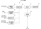
- FIG. 2 is a block diagram showing the configuration of the main part of the area terminal.
- the area terminal 1 includes a control unit 11, a moving image input unit 12, an image processing unit 13, an imaging visual field control unit 14, an imaging instruction unit 15, a still image input unit 16, an image storage unit 17, and a communication. Part 18.
- the control unit 11 controls the operation of each part of the area terminal 1 main body.
- the moving image input unit 12 receives a moving image of the monitoring target area captured by the video camera 2.
- the video camera 2 inputs a captured image of 30 frames per second to the moving image input unit 12.
- the image processing unit 13 For each frame image input to the moving image input unit 12, the image processing unit 13 generates a difference image between the frame image and the background image of the monitoring target area, and uses the generated difference image in the monitoring target area. It is detected whether or not an object that is positioned (suspicious person or suspicious object) is imaged. As is known, objects such as suspicious persons and suspicious objects located in the monitoring target area appear in the difference image.
- the imaging field controller 14 controls the imaging field of the digital still camera 3. Specifically, the imaging visual field control unit 14 individually controls the panning direction and the rotation angle in the tilt direction of the pan head to which the digital still camera 3 is attached. A driving mechanism (not shown) for rotating the pan head in the pan direction and the tilt direction is provided on the pan head. In other words, the imaging visual field control unit 14 controls the rotation mechanism in the pan direction and the tilt direction by controlling the pan head drive mechanism. The imaging direction of the digital still camera 3 is changed by changing the pan angle of the pan head and the rotation angle in the tilt direction. Further, the imaging visual field control unit 14 instructs the digital still camera 3 on the imaging magnification.
- the imaging instruction unit 15 inputs a release signal to the digital still camera 3.
- the still image input unit 16 receives a still image captured by the digital still camera 3.
- the image storage unit 17 includes a recording medium such as a hard disk that stores a moving image of the monitoring target area captured by the video camera 2, that is, a moving image input to the moving image input unit 12.
- a recording medium such as a hard disk that stores a moving image of the monitoring target area captured by the video camera 2, that is, a moving image input to the moving image input unit 12.
- the communication unit 18 controls communication with the server 4 via the network 5.
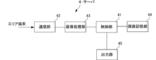
- FIG. 3 is a block diagram showing the configuration of the main part of the server.
- the server 4 includes a control unit 41, a communication unit 42, an image processing unit 43, an image storage unit 44, and an output unit 45.
- the control unit 41 controls the operation of each part of the server 4 main body.
- the communication unit 42 controls communication with the area terminal 1 via the network 5.
- the image processing unit 43 processes the still image transmitted from the area terminal 1 and detects attributes such as the type and size of the imaged object.
- the image processing unit 43 performs image processing related to known pattern matching and the like, and detects attributes such as the type and size of the object being imaged. If the detected object is a person, face recognition processing is performed to estimate gender, age, and the like. If the detected object is a vehicle, a character recognition process for recognizing the license plate number written on the license plate is performed.
- the image storage unit 44 stores the still image transmitted from the area terminal 1.
- the output unit 45 performs output based on the result of image processing in the image processing unit 43. For example, when a suspicious person or a suspicious object is detected, the detected suspicious person, the type and size of the suspicious object, etc., are used as a processing result, and an alarm in the security room is activated to a guard who is waiting. Notification is performed and the processing result is transmitted by e-mail to a portable terminal possessed by a security guard or the like.
- the imaging area of the video camera 2 corresponds to the monitoring target area assigned to the connected area terminal 1 as described above.
- the imaging area of the video camera 2 is fixed.
- the size of the imaging area of the digital still camera 3 can be changed according to the imaging magnification, and the monitoring target can be changed by changing the panning direction and the rotation angle of the tilting direction of the pan head attached. Can be adjusted to any position in the area.
- FIG. 5 is a flowchart showing the operation of the area terminal.
- FIG. 6 is a flowchart showing the operation of the server.
- the area terminal 1 determines the difference between the frame image and the background image of the monitoring target area in the image processing unit 13. An image is generated (S2).
- the image processing unit 13 detects the presence or absence of an object (suspicious person or suspicious object) located in the monitoring target area from the difference image generated in S2 (S3).
- the area terminal 1 detects that no object is located in the monitoring target area in S3, the area terminal 1 returns to S1.
- the area terminal 1 detects an object located in the monitoring target area in S3
- the area terminal 1 detects the position (position in the monitoring target area) and the size of the object (S4).
- the position of the object in the monitoring target area can be detected from the position of the object on the frame image.
- the size of the object can be detected from the size of the object on the frame image.
- the imaging field control unit 14 calculates the pan angle and tilt angle of the pan head to which the digital still camera 3 is attached, and the digital still The imaging magnification of the camera 3 is calculated (S5).
- S ⁇ b> 5 the rotation angle in the pan direction and the tilt direction and the imaging magnification of the digital still camera 3 are calculated so that the entire object detected in S ⁇ b> 3 is within the imaging field of view of the digital still camera 3.
- the imaging magnification of the digital still camera 3 can be larger than the imaging magnification of the video camera 2. Therefore, the detected image of the digital still camera 3 is captured more clearly than the captured image of the video camera 2.
- the imaging field-of-view control unit 14 instructs the pan / tilt rotation angle calculated in S5 to the pan / tilt head to which the digital still camera 3 is attached, and instructs the digital still camera 3 to set the imaging magnification. (S6). Thereby, the pan head rotates in the pan direction and the tilt direction, and the imaging direction of the digital still camera 3 is changed. The digital still camera 3 changes the imaging magnification to the magnification instructed this time.
- the imaging instruction unit 15 inputs a release signal to the digital still camera 3 (S7).
- the digital still camera 3 performs imaging in the imaging field of view at this time, and inputs the captured still image to the still image input unit 16.
- the area terminal 1 adjusts the imaging field of view of the digital still camera 3 in accordance with the position and size of the object detected this time, the detected object is detected from the frame image captured by the video camera 2. A still image captured clearly can be obtained.
- the area terminal 1 transmits the still image to the server 4 (S9). At this time, the area terminal 1 also transmits to the server 4 the position of the object detected in S4 and the imaging magnification of the digital still camera 3 calculated in S5.
- the area terminal 1 may always store the moving image of the monitored area captured by the video camera 2 input to the moving image input unit 12 in the image storage unit 17. In order to suppress this, the timing at which the object is detected in S3 is set as the start timing, and thereafter, the moving image of the monitoring target area captured by the video camera 2 input to the moving image input unit 12 is stored for a certain period of time. Also good.
- the area terminal 1 can sufficiently suppress the processing load of the image processing in the image processing unit 13 related to the detection of the object and the processing load related to the transmission of the image to the server 4.
- the image processing unit 43 processes the still image received this time. (S12).
- S12 unlike the image processing unit 13 of the area terminal 1 described above, image processing related to pattern matching is performed, and attributes such as the type and size of the object captured in the still image received this time are detected.
- the server 4 performs pattern matching in the image processing unit 43 to determine whether the object being imaged is a person or a vehicle that is a moving body, or a bag or suitcase that is a non-moving body. Detect by.
- the server 4 performs face recognition processing by the image processing unit 43 and estimates sex, age, and the like. Further, if the detected object is a vehicle, the server 4 performs character recognition processing for recognizing the license plate number written on the license plate of the vehicle by the image processing unit 43.
- the server 4 receives the imaging magnification when the digital still camera 3 captures the still image received by the communication unit 42 from the area terminal 1, so that the object size is determined from the size of the object on the still image. The actual size of can be calculated.
- the server 4 performs output according to the detection result in S12 in the output unit 45 (S13). For example, the type and size of the suspicious person detected this time, the type and size of the suspicious object, etc. as the processing result, the alarm in the security room is activated to notify the waiting security guard, etc.
- the processing result is transmitted by e-mail to the mobile terminal.
- the server 4 stores the still image transmitted from the area terminal 1 connected via the network 5 in the image storage unit 44.
- the area terminal 1 can sufficiently suppress the processing load of the image processing in the image processing unit 13 related to the detection of the object and the processing load related to the transmission of the image to the server 4.
- the object attribute detected by the area terminal 1 is detected on the server 4 side.
- the server 4 does not perform detection related to the presence or absence of an object.
- the still image used for the server 4 to detect the attribute of the object is an image obtained by clearly capturing the object detected by the digital still camera 3. For this reason, the server 4 can detect the attribute of the object located in the monitoring target area with high accuracy. Further, since the area terminal 1 transmits a still image in which the detected object is captured to the server 4 and does not transmit a moving image captured by the video camera 2 to the server 4, the traffic amount of the network 5 can also be suppressed. it can.
- the area terminal 1 can be used without any problem even if it is an inexpensive one with low processing performance. Moreover, the detection of the object located in the monitoring target area and the detection of the attribute can be accurately performed on the server 4 side. Thereby, the detection of the object located in the monitoring object area and the detection of the attribute can be performed with high accuracy, and the increase in the cost for constructing the system can be suppressed.
- the digital still camera 3, the pan head, the imaging field of view control unit 14, the imaging instruction unit 15, and the still image input unit 16 of the area terminal 1 are eliminated, and an object detected by the area terminal 1 is captured.
- the frame image of the video camera 2 may be transmitted to the server 4 as a still image. In this way, the processing load on the area terminal 1 can be further reduced.
- the area terminal 1 may be configured to transmit the frame image of the video camera 2 in which the detected object is imaged and the still image in which the digital still camera 3 images the detected object to the server 4. .
- the area terminal 1 may detect whether the detected object is a moving object or a non-moving object and notify the server 4 of the detected object.
- the area terminal 1 can detect whether the detected object is a moving object or a non-moving object depending on whether or not the position of the detected object changes with time.
- the server 4 can perform pattern matching with respect to the object captured in the still image only on the moving body or the non-moving body notified from the area terminal 1. That is, the load on the image processing on the server 4 side can also be reduced.
Landscapes
- Engineering & Computer Science (AREA)
- Multimedia (AREA)
- Signal Processing (AREA)
- Theoretical Computer Science (AREA)
- Physics & Mathematics (AREA)
- General Physics & Mathematics (AREA)
- Computer Vision & Pattern Recognition (AREA)
- Artificial Intelligence (AREA)
- Software Systems (AREA)
- Human Computer Interaction (AREA)
- Computing Systems (AREA)
- General Engineering & Computer Science (AREA)
- Closed-Circuit Television Systems (AREA)
- Alarm Systems (AREA)
- Two-Way Televisions, Distribution Of Moving Picture Or The Like (AREA)
- Image Analysis (AREA)
Abstract
L'invention porte sur un système de traitement d'image distribué qui peut effectuer, avec une précision élevée, la détection d'un objet situé dans une zone à surveiller et la détection de ses attributs, et qui peut supprimer l'accroissement de coût de structuration du système. Un terminal de zone (1) traite une image prise par une caméra vidéo (2) et détecte s'il existe un quelconque objet dans l'image prise. Le terminal de zone (1), lorsqu'il a détecté un objet situé dans une zone à surveiller, règle le champ visuel de prise de vue d'un appareil photo numérique (3) sur l'objet détecté, et applique un signal de déclenchement à l'appareil photo numérique (3). Le terminal de zone (1) émet ensuite une image fixe, qui a été prise par l'appareil photo numérique (3), à un serveur (4) par l'intermédiaire d'un réseau (5). Le serveur (4) traite l'image fixe, qui a été émise par le terminal de zone (1), afin de détecter les attributs, tels que type, taille et ainsi de suite, de l'objet dans l'image prise. Le serveur (4) effectue ensuite une sortie en fonction d'un résultat de détection de l'objet situé dans la zone à surveiller.
Priority Applications (4)
| Application Number | Priority Date | Filing Date | Title |
|---|---|---|---|
| CN201280024655.1A CN103548341A (zh) | 2011-06-08 | 2012-02-21 | 分布图像处理系统 |
| EP12796757.8A EP2720459B1 (fr) | 2011-06-08 | 2012-02-21 | Système de traitement d'image distribué |
| JP2013519400A JP5790761B2 (ja) | 2011-06-08 | 2012-02-21 | 分散画像処理システム |
| US14/119,617 US20140146172A1 (en) | 2011-06-08 | 2012-02-21 | Distributed image processing system |
Applications Claiming Priority (2)
| Application Number | Priority Date | Filing Date | Title |
|---|---|---|---|
| JP2011-127812 | 2011-06-08 | ||
| JP2011127812 | 2011-06-08 |
Publications (1)
| Publication Number | Publication Date |
|---|---|
| WO2012169232A1 true WO2012169232A1 (fr) | 2012-12-13 |
Family
ID=47295806
Family Applications (1)
| Application Number | Title | Priority Date | Filing Date |
|---|---|---|---|
| PCT/JP2012/054068 Ceased WO2012169232A1 (fr) | 2011-06-08 | 2012-02-21 | Système de traitement d'image distribué |
Country Status (5)
| Country | Link |
|---|---|
| US (1) | US20140146172A1 (fr) |
| EP (1) | EP2720459B1 (fr) |
| JP (1) | JP5790761B2 (fr) |
| CN (1) | CN103548341A (fr) |
| WO (1) | WO2012169232A1 (fr) |
Cited By (6)
| Publication number | Priority date | Publication date | Assignee | Title |
|---|---|---|---|---|
| WO2017110028A1 (fr) * | 2015-12-25 | 2017-06-29 | パナソニックIpマネジメント株式会社 | Appareil, système et procédé de surveillance d'objets abandonnés |
| WO2018116494A1 (fr) * | 2016-12-22 | 2018-06-28 | 日本電気株式会社 | Caméra de surveillance, système de surveillance, procédé de commande de caméra de surveillance, et programme |
| JP2019125258A (ja) * | 2018-01-18 | 2019-07-25 | アイシン・エィ・ダブリュ株式会社 | 情報収集システム、及び情報収集プログラム |
| JP2019176471A (ja) * | 2018-03-29 | 2019-10-10 | 株式会社リコー | 通信システム、及び通信方法 |
| JP2021164008A (ja) * | 2020-03-30 | 2021-10-11 | 大日本印刷株式会社 | 情報処理方法、情報処理装置、プログラム及び情報処理システム |
| WO2022070808A1 (fr) * | 2020-10-01 | 2022-04-07 | 富士フイルム株式会社 | Dispositif de traitement d'informations de catastrophe, procédé de fonctionnement d'un dispositif de traitement d'informations de catastrophe, programme de fonctionnement d'un dispositif de traitement d'informations de catastrophe, et système de traitement d'informations de catastrophe |
Families Citing this family (19)
| Publication number | Priority date | Publication date | Assignee | Title |
|---|---|---|---|---|
| US20140203947A1 (en) * | 2013-01-20 | 2014-07-24 | Alan Haddy | Storage and recall of buried asset data over communications networks for damage avoidance and mapping |
| JP2016129269A (ja) * | 2013-04-22 | 2016-07-14 | パナソニック株式会社 | 画像・音声処理装置、集積回路、およびプログラム |
| US9524418B2 (en) | 2014-06-05 | 2016-12-20 | Promethean Limited | Systems and methods for detecting, identifying and tracking objects and events over time |
| US9269159B2 (en) | 2014-06-05 | 2016-02-23 | Promethean Limited | Systems and methods for tracking object association over time |
| CN104092941A (zh) * | 2014-07-10 | 2014-10-08 | 深圳市得意自动化科技有限公司 | 摄像元件的摄像方法 |
| US10326922B2 (en) | 2014-07-23 | 2019-06-18 | Orcam Technologies Ltd. | Wearable apparatus and method for capturing image data using multiple image sensors |
| JP2016134103A (ja) * | 2015-01-21 | 2016-07-25 | 富士ゼロックス株式会社 | 監視システム |
| JP6266577B2 (ja) * | 2015-10-02 | 2018-01-24 | 京セラ株式会社 | 電子機器 |
| US10885788B2 (en) * | 2017-04-24 | 2021-01-05 | Mitsubishi Electric Corporation | Notification control apparatus and method for controlling notification |
| JP6948175B2 (ja) | 2017-07-06 | 2021-10-13 | キヤノン株式会社 | 画像処理装置およびその制御方法 |
| US10795933B1 (en) | 2018-05-01 | 2020-10-06 | Flock Group Inc. | System and method for object based query of video content captured by a dynamic surveillance network |
| US10559200B1 (en) | 2018-05-01 | 2020-02-11 | Flock Group Inc. | Method and system for capturing and storing significant surveillance images |
| CN111028313B (zh) * | 2019-12-26 | 2020-10-09 | 浙江口碑网络技术有限公司 | 桌台分布图像生成方法及装置 |
| CN116405773A (zh) * | 2020-12-29 | 2023-07-07 | 华为技术有限公司 | 一种拍摄方法、系统及电子设备 |
| CN112991670A (zh) * | 2021-02-04 | 2021-06-18 | 西安美格智联软件科技有限公司 | 消防危险区域分类管控方法、系统、存储介质、处理终端 |
| EP4099679A1 (fr) * | 2021-05-31 | 2022-12-07 | Robert Bosch GmbH | Procédé et appareil permettant de faire fonctionner un système de commande de caméra |
| US12132986B2 (en) * | 2021-12-12 | 2024-10-29 | Avanti R&D, Inc. | Computer vision system used in vehicles |
| TWI815495B (zh) * | 2022-06-06 | 2023-09-11 | 仁寶電腦工業股份有限公司 | 動態影像之處理方法、電子裝置及其連接之終端裝置與行動通訊裝置 |
| US20250245989A1 (en) * | 2024-01-30 | 2025-07-31 | Alarm.Com Incorporated | Camera |
Citations (7)
| Publication number | Priority date | Publication date | Assignee | Title |
|---|---|---|---|---|
| JP2003116139A (ja) * | 2001-10-03 | 2003-04-18 | Olympus Optical Co Ltd | 映像配信サーバ及び映像受信クライアントシステム |
| JP2006238102A (ja) * | 2005-02-25 | 2006-09-07 | Sony Corp | 撮像装置および画像配信方法 |
| JP2006332881A (ja) * | 2005-05-24 | 2006-12-07 | Canon Inc | 監視撮影システム、撮影方法、コンピュータプログラム及び記録媒体 |
| JP2007233495A (ja) * | 2006-02-28 | 2007-09-13 | Hitachi Ltd | 分散型画像処理装置 |
| JP2009038779A (ja) | 2007-08-06 | 2009-02-19 | Shinji Kobayashi | 移動体検知装置、移動体撮像システム、移動体撮像方法、および移動体検知プログラム |
| JP2010177893A (ja) | 2009-01-28 | 2010-08-12 | Osaka Prefecture | 撮像制御装置、および撮像制御方法 |
| JP2010226687A (ja) * | 2009-02-27 | 2010-10-07 | Sony Corp | 画像処理装置、画像処理システム、カメラ装置、画像処理方法、およびプログラム |
Family Cites Families (19)
| Publication number | Priority date | Publication date | Assignee | Title |
|---|---|---|---|---|
| JPH0944759A (ja) * | 1995-07-28 | 1997-02-14 | Oki Electric Ind Co Ltd | 監視装置 |
| JPH11112966A (ja) * | 1997-10-07 | 1999-04-23 | Canon Inc | 動体検出装置、動体検出方法及びコンピュータ読み取り可能な記憶媒体 |
| US6731805B2 (en) * | 2001-03-28 | 2004-05-04 | Koninklijke Philips Electronics N.V. | Method and apparatus to distinguish deposit and removal in surveillance video |
| JP4156893B2 (ja) * | 2002-09-27 | 2008-09-24 | 富士フイルム株式会社 | 画像処理装置、方法及びプログラム |
| GB0226002D0 (en) * | 2002-11-07 | 2002-12-11 | Home Networking Ltd | Surveillance device |
| CN1194484C (zh) * | 2003-01-30 | 2005-03-23 | 张健 | 一种可视化家居安防系统和进行实时监控、传输的方法 |
| JP4140402B2 (ja) * | 2003-03-03 | 2008-08-27 | 松下電工株式会社 | 画像処理装置 |
| JP4622301B2 (ja) * | 2004-05-07 | 2011-02-02 | オムロン株式会社 | 監視システム、および監視カメラ |
| CN100478862C (zh) * | 2005-10-05 | 2009-04-15 | 索尼株式会社 | 显示装置和显示方法 |
| CN100547351C (zh) * | 2007-02-01 | 2009-10-07 | 华中科技大学 | 一种机器视觉定位方法 |
| JP2008283629A (ja) * | 2007-05-14 | 2008-11-20 | Sony Corp | 撮像装置、撮像信号処理方法、プログラム |
| CN101329176A (zh) * | 2007-06-20 | 2008-12-24 | 贝联特种金属制品(上海)有限公司 | 一种在线影像检测系统 |
| JP4975679B2 (ja) * | 2008-04-18 | 2012-07-11 | 株式会社Pfu | ノート型情報処理装置、および、射影変換パラメータ算出方法 |
| CN101765025A (zh) * | 2008-12-23 | 2010-06-30 | 北京中星微电子有限公司 | 一种监控摄像设备异常检测的系统及方法 |
| CN102044064A (zh) * | 2009-10-23 | 2011-05-04 | 鸿富锦精密工业(深圳)有限公司 | 影像处理系统及方法 |
| CN101833813B (zh) * | 2010-03-03 | 2012-06-13 | 杭州创导安全技术有限公司 | 一种atm机异物入侵检测报警装置及检测报警方法 |
| US9082278B2 (en) * | 2010-03-19 | 2015-07-14 | University-Industry Cooperation Group Of Kyung Hee University | Surveillance system |
| CN201750493U (zh) * | 2010-07-02 | 2011-02-16 | 湖南云博信息技术有限公司 | 智能型双cmos摄像机 |
| CN101969548B (zh) * | 2010-10-15 | 2012-05-23 | 中国人民解放军国防科学技术大学 | 基于双目摄像的主动视频获取方法及装置 |
-
2012
- 2012-02-21 WO PCT/JP2012/054068 patent/WO2012169232A1/fr not_active Ceased
- 2012-02-21 US US14/119,617 patent/US20140146172A1/en not_active Abandoned
- 2012-02-21 CN CN201280024655.1A patent/CN103548341A/zh active Pending
- 2012-02-21 JP JP2013519400A patent/JP5790761B2/ja not_active Expired - Fee Related
- 2012-02-21 EP EP12796757.8A patent/EP2720459B1/fr not_active Not-in-force
Patent Citations (7)
| Publication number | Priority date | Publication date | Assignee | Title |
|---|---|---|---|---|
| JP2003116139A (ja) * | 2001-10-03 | 2003-04-18 | Olympus Optical Co Ltd | 映像配信サーバ及び映像受信クライアントシステム |
| JP2006238102A (ja) * | 2005-02-25 | 2006-09-07 | Sony Corp | 撮像装置および画像配信方法 |
| JP2006332881A (ja) * | 2005-05-24 | 2006-12-07 | Canon Inc | 監視撮影システム、撮影方法、コンピュータプログラム及び記録媒体 |
| JP2007233495A (ja) * | 2006-02-28 | 2007-09-13 | Hitachi Ltd | 分散型画像処理装置 |
| JP2009038779A (ja) | 2007-08-06 | 2009-02-19 | Shinji Kobayashi | 移動体検知装置、移動体撮像システム、移動体撮像方法、および移動体検知プログラム |
| JP2010177893A (ja) | 2009-01-28 | 2010-08-12 | Osaka Prefecture | 撮像制御装置、および撮像制御方法 |
| JP2010226687A (ja) * | 2009-02-27 | 2010-10-07 | Sony Corp | 画像処理装置、画像処理システム、カメラ装置、画像処理方法、およびプログラム |
Non-Patent Citations (1)
| Title |
|---|
| See also references of EP2720459A4 |
Cited By (17)
| Publication number | Priority date | Publication date | Assignee | Title |
|---|---|---|---|---|
| CN108369770B (zh) * | 2015-12-25 | 2019-10-29 | 松下知识产权经营株式会社 | 丢弃物监视装置和具备该丢弃物监视装置的丢弃物监视系统以及丢弃物监视方法 |
| JP2017117349A (ja) * | 2015-12-25 | 2017-06-29 | パナソニックIpマネジメント株式会社 | 置去り物監視装置およびこれを備えた置去り物監視システムならびに置去り物監視方法 |
| GB2558841B (en) * | 2015-12-25 | 2021-04-07 | Panasonic Ip Man Co Ltd | Unattended object monitoring apparatus, unattended object monitoring system provided with same, and unattended object monitoring method |
| GB2558841A (en) * | 2015-12-25 | 2018-07-18 | Panasonic Ip Man Co Ltd | Unattended object monitoring apparatus, unattended object monitoring system provided with same, and unattended object monitoring method |
| CN108369770A (zh) * | 2015-12-25 | 2018-08-03 | 松下知识产权经营株式会社 | 丢弃物监视装置和具备该丢弃物监视装置的丢弃物监视系统以及丢弃物监视方法 |
| WO2017110028A1 (fr) * | 2015-12-25 | 2017-06-29 | パナソニックIpマネジメント株式会社 | Appareil, système et procédé de surveillance d'objets abandonnés |
| JPWO2018116494A1 (ja) * | 2016-12-22 | 2019-11-07 | 日本電気株式会社 | 監視カメラ、監視システム、監視カメラの制御方法及びプログラム |
| WO2018116494A1 (fr) * | 2016-12-22 | 2018-06-28 | 日本電気株式会社 | Caméra de surveillance, système de surveillance, procédé de commande de caméra de surveillance, et programme |
| JP2019125258A (ja) * | 2018-01-18 | 2019-07-25 | アイシン・エィ・ダブリュ株式会社 | 情報収集システム、及び情報収集プログラム |
| JP2019176471A (ja) * | 2018-03-29 | 2019-10-10 | 株式会社リコー | 通信システム、及び通信方法 |
| JP7251247B2 (ja) | 2018-03-29 | 2023-04-04 | 株式会社リコー | 通信システム、及び通信方法 |
| JP2021164008A (ja) * | 2020-03-30 | 2021-10-11 | 大日本印刷株式会社 | 情報処理方法、情報処理装置、プログラム及び情報処理システム |
| JP7447626B2 (ja) | 2020-03-30 | 2024-03-12 | 大日本印刷株式会社 | 情報処理方法、情報処理装置、プログラム及び情報処理システム |
| WO2022070808A1 (fr) * | 2020-10-01 | 2022-04-07 | 富士フイルム株式会社 | Dispositif de traitement d'informations de catastrophe, procédé de fonctionnement d'un dispositif de traitement d'informations de catastrophe, programme de fonctionnement d'un dispositif de traitement d'informations de catastrophe, et système de traitement d'informations de catastrophe |
| JPWO2022070808A1 (fr) * | 2020-10-01 | 2022-04-07 | ||
| US12207021B2 (en) | 2020-10-01 | 2025-01-21 | Fujifilm Corporation | Disaster information processing apparatus, operation method of disaster information processing apparatus, operation program of disaster information processing apparatus, and disaster information processing system |
| JP7641980B2 (ja) | 2020-10-01 | 2025-03-07 | 富士フイルム株式会社 | 災害情報処理装置、災害情報処理装置の作動方法、災害情報処理装置の作動プログラム、並びに災害情報処理システム |
Also Published As
| Publication number | Publication date |
|---|---|
| EP2720459A1 (fr) | 2014-04-16 |
| EP2720459A4 (fr) | 2015-04-22 |
| CN103548341A (zh) | 2014-01-29 |
| US20140146172A1 (en) | 2014-05-29 |
| EP2720459B1 (fr) | 2020-07-08 |
| JP5790761B2 (ja) | 2015-10-07 |
| JPWO2012169232A1 (ja) | 2015-02-23 |
Similar Documents
| Publication | Publication Date | Title |
|---|---|---|
| JP5790761B2 (ja) | 分散画像処理システム | |
| JP7420169B2 (ja) | 監視システム、監視方法及びプログラム | |
| US7536028B2 (en) | Monitoring camera system, monitoring camera control device and monitoring program recorded in recording medium | |
| CN110072078B (zh) | 监控摄像机、监控摄像机的控制方法和存储介质 | |
| EP3024227A1 (fr) | Appareil et procédé de traitement des images | |
| US8406468B2 (en) | Image capturing device and method for adjusting a position of a lens of the image capturing device | |
| JP5274216B2 (ja) | 監視システム及び監視方法 | |
| US8249300B2 (en) | Image capturing device and method with object tracking | |
| US9386050B2 (en) | Method and apparatus for filtering devices within a security social network | |
| JP2007158860A (ja) | 撮影システム、撮影装置、画像切替装置、およびデータ保持装置 | |
| US20140285659A1 (en) | Intelligent central surveillance server system and controlling method thereof | |
| US20170347068A1 (en) | Image outputting apparatus, image outputting method and storage medium | |
| US9167048B2 (en) | Method and apparatus for filtering devices within a security social network | |
| JP3942606B2 (ja) | 変化検出装置 | |
| EP3018902B1 (fr) | Système de caméra de surveillance | |
| KR101020670B1 (ko) | 원격테스트 기능을 구비한 방범 시스템 | |
| US20070296813A1 (en) | Intelligent monitoring system and method | |
| JP2021111033A (ja) | 物体監視装置、物体監視プログラム、及び監視システム | |
| JP2018170574A (ja) | 監視システム | |
| US20110267463A1 (en) | Image capturing device and method for controlling image capturing device | |
| JP2005347942A (ja) | 監視システム、監視システムの制御プログラム、および監視装置 | |
| JP7746114B2 (ja) | 画像処理装置、画像処理方法、画像処理システム、およびプログラム | |
| US20140273989A1 (en) | Method and apparatus for filtering devices within a security social network | |
| WO2013145639A1 (fr) | Dispositif de traitement d'informations, procédé de traitement d'informations et programme | |
| JP2013115566A (ja) | 撮像装置、撮像装置の制御方法及びプログラム |
Legal Events
| Date | Code | Title | Description |
|---|---|---|---|
| 121 | Ep: the epo has been informed by wipo that ep was designated in this application |
Ref document number: 12796757 Country of ref document: EP Kind code of ref document: A1 |
|
| ENP | Entry into the national phase |
Ref document number: 2013519400 Country of ref document: JP Kind code of ref document: A |
|
| NENP | Non-entry into the national phase |
Ref country code: DE |
|
| WWE | Wipo information: entry into national phase |
Ref document number: 14119617 Country of ref document: US |