WO2012173092A1 - ボイラ施設建設工法 - Google Patents
ボイラ施設建設工法 Download PDFInfo
- Publication number
- WO2012173092A1 WO2012173092A1 PCT/JP2012/064923 JP2012064923W WO2012173092A1 WO 2012173092 A1 WO2012173092 A1 WO 2012173092A1 JP 2012064923 W JP2012064923 W JP 2012064923W WO 2012173092 A1 WO2012173092 A1 WO 2012173092A1
- Authority
- WO
- WIPO (PCT)
- Prior art keywords
- boiler
- floor unit
- installation
- floor
- construction method
- Prior art date
- Legal status (The legal status is an assumption and is not a legal conclusion. Google has not performed a legal analysis and makes no representation as to the accuracy of the status listed.)
- Ceased
Links
Images




Classifications
-
- F—MECHANICAL ENGINEERING; LIGHTING; HEATING; WEAPONS; BLASTING
- F22—STEAM GENERATION
- F22B—METHODS OF STEAM GENERATION; STEAM BOILERS
- F22B37/00—Component parts or details of steam boilers
- F22B37/02—Component parts or details of steam boilers applicable to more than one kind or type of steam boiler
- F22B37/24—Supporting, suspending or setting arrangements, e.g. heat shielding
- F22B37/244—Supporting, suspending or setting arrangements, e.g. heat shielding for water-tube steam generators suspended from the top
Definitions
- the present invention relates to construction of a large boiler and its building, and more particularly to a construction method of a boiler facility suitable for shortening a construction period until a boiler used for a power generation facility installed in a suspended state in a building is installed in the building. .
- Boilers employed in thermal power plant facilities are large in size, and are expanded by heating, so that they are suspended from a structure called a girder provided at the top end of the facility building. In the construction of a boiler having such a structure, improvement of work safety and shortening of the construction period have been problems.
- a thermal power plant facility equipped with a boiler is roughly composed of a side-span steel frame that forms the side wall of the building and is equipped with piping facilities, a large beam that spans the upper part of the pair of side-span steel frames, A boiler body suspended from the girder.
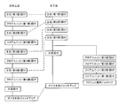
- a thermal power plant facility having such a structure has been constructed by a process as shown in FIG. That is, after assembling one main column provided on the four sides of the side span steel frame, the main column of the assembled node, the floor unit that fits in the side span steel frame, and piping are installed. Repeat these steps as many times as needed to complete the side-span steel frame (steps 1-5). Next, the girder spanned between the side span steel frames is lifted and fixed to the upper part of the side span steel frames (step 6). After that, the boiler is lifted based on the large beam. Here, the boiler is divided into a plurality of units (three in the example shown in FIG. 7), and the lower unit is sequentially engaged while pulling up the upper unit. Installation can be performed in parallel (steps 7-9). Assembling a thermal power plant facility in such a process is disclosed in Patent Document 1, for example.
- Patent Document 2 discloses a construction method for shortening the construction period of the thermal power plant facility having such a configuration.
- the construction method disclosed in Patent Document 2 first, four main pillars constituting a side span steel frame are erected. Thereafter, a floor module in which a floor unit, piping and the like are incorporated is arranged between the main pillars.
- each floor module is carried in after being assembled in advance in a factory, and is lifted up to a predetermined position and installed by a jack arranged on the upper part of the main pillar.
- the connection material which prevents the fall of a side span steel frame is provided between the main pillars.
- the boiler module disclosed in Patent Document 2 is a separate type module, and includes a large beam for suspending the boiler, an upper module including a boiler upper unit, and a lower module including a boiler lower unit.
- the upper module and the lower module are each assembled after being assembled at the factory.
- an object of the present invention is to provide a boiler facility construction method capable of shortening the construction period until the boiler is installed with respect to the construction of a large boiler and its building.
- a boiler facility construction method includes a main pillar installation process for installing a main pillar of a boiler building, and a plurality of jack devices provided on the upper part of the main pillar after the main pillar installation process.
- a floor unit installation process for lifting and fixing the floor units constituting each floor of the main pillar by a plurality of jack devices provided on the upper part of the main pillar. It is characterized by having.
- the floor unit installation step is jacked up after a step of jacking up by connecting a rod unit of the jack device and a floor unit arranged at the top.
- the floor unit placed on the lower floor of the floor unit is jacked up to the floor where each floor unit is to be installed by repeating the process of jacking up by connecting the floor unit to the lower side of the jacked floor unit with a temporary suspension. It is better to install it and install it.
- the floor unit installation process may be completed before the boiler installation process is completed.
- the main pillar installation process also performs installation of beams and steel frames that prevent the main pillar from falling down. By doing in this way, it is possible to prevent the side span steel frame from falling inward when lifting a relatively heavy heavy beam or the like.
- the jack apparatus used in the large beam installation process, the boiler installation process, and the floor unit installation process may be partially or entirely used in each process. .
- the jack device that is mutually used in each process may be moved during execution of another process after the use in each process is completed. By doing in this way, the time required only for the movement of the jack device can be eliminated, and the time required for each process can be shortened.
- the rods of the jack device used in the large beam installation process, the boiler installation process, and the floor unit installation process can be shared and used in common. desirable.
- the rods can be easily managed, and the number of unused rods can be reduced by the mutual use of the rods, and the total number of rods used can be reduced.
- an external crane is used for the main pillar installation process, the external crane is removed after the main pillar installation process is finished, a large beam installation process, a boiler installation process, and The floor unit installation process is preferably performed using a jack device.
- the front block diagram for demonstrating each process in the construction method of the boiler facility which concerns on embodiment is shown.
- the plane block diagram for demonstrating each process in the construction method of the boiler facility which concerns on embodiment is shown.
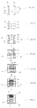
- FIG. 1 is a diagram showing a front configuration of the boiler facility
- FIG. 2 is a diagram showing a side configuration of the boiler facility.
- the boiler facility 10 has a boiler building 12 and a boiler body 30 installed in the building.
- the boiler building 12 includes a side span steel frame 20 that constitutes a side wall and installs piping and the like (not shown), a steel frame 16 before the can that prevents the side span steel frame 20 from falling, and a steel frame 15 after the can (see FIG. 3-2). ), A large beam 22, a wisteria steel frame 24, and the like.
- the side span steel frame 20 has four main pillars 14 installed on four sides of the building, and a garter beam 18 that connects two of the four main pillars 14 to form a side wall.
- the main pillar 14 is composed of four struts 13.
- the side span steel frame 20 is divided into a plurality of levels, and a floor unit 14a and piping (not shown) are installed for each level.
- the steel frame 16 in front of the can is a beam provided between the pair of side span steel frames 20 so as to constitute the front wall of the boiler building 12.
- the steel frame 16 before the can plays a role of preventing the side span steel frames 20 from falling inward (sides facing each other) when lifting heavy objects such as large beams on the side span steel frames 20.
- the post-can steel frame 15 is a beam provided to constitute the rear wall of the boiler building 12 so as to face the above-mentioned pre-can steel frame 16.
- the large beam 22 is a beam that is connected to the joint 21 provided at the upper end of the main pillar 14 constituting the side span steel frame 20 and is provided so as to span the upper end of the pair of side span steel frames 20. As shown in FIG. 3A, the connection surface between the joint 21 and the large beam 22 is inclined because the method of Japanese Patent No. 3389839 is used.
- a plurality of small beams called wisteria steel frames 24 are stretched in the front-rear direction of the boiler building 12 on the lower side of the large beams 22.
- the boiler body 30, which will be described in detail later, is suspended under the wisteria trellis steel frame 24 based on the large beam 22.
- the boiler body 30 is suspended from a wisteria trellis steel frame 24 installed with the large beam 22 as a reference.
- the boiler body 30 according to the embodiment is composed of a plurality of units. In the example shown in FIGS. 1 to 3-1 and 3-2, three units (an upper unit 32, an intermediate unit 34, and a lower unit 36) are shown for ease of explanation.
- FIG. 3A is a diagram illustrating a front configuration
- FIG. 3B is a diagram illustrating a top configuration.
- the first and second sections of the main pillar 14 composed of a plurality of layers are installed.
- the garter beam 18 and the steel frame 16 before the can are installed between the main pillars 14 of the first node.
- the installation work of the main pillar 14 and the installation work of the garter beam 18, the steel frame 16 before the can, and the steel frame 15 after the can are performed by an external crane (not shown) arranged around the boiler building construction site (step 1).
- the third and fourth sections of the main pillar 14 are installed.
- the garter beam 18 and the front steel frame 16 are installed between the main columns 14 of the second node, and when installing the fourth node, the main column 14 of the third node.
- the garter beam 18 and the pre-can steel frame 16 are installed between them (step 2).
- the garter beam 18 and the pre-can steel frame 16 are installed between the main pillars 14 of the fourth knot.
- a joint 21 serving as a base for fixing the large beam 22 is attached to the upper end of the main column, and a jack device 40 for lifting the large beam 22 and the floor unit 14a is provided at the upper end of the main column 14. It is lifted up.
- the floor unit 14a is started to be lifted and installed (step 3: floor unit installation process).
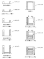
- the floor unit installation process as shown in FIG. 4, the floor unit 14a arranged on the upper floor is lifted with the floor units 14a arranged on the lower floor sequentially connected.
- the rod 40a of the jack device 40 arranged on the upper part of the main pillar 14 is connected to the uppermost part (the floor unit 14a arranged on the uppermost floor, and this is jacked up.
- the floor unit 14a disposed on the lower floor is disposed below the floor unit disposed on the uppermost portion, and disposed on the upper floor.
- the floor unit 14a to be disposed and the floor unit 14a to be disposed on the lower floor are connected by the temporary suspension member 50.
- the floor unit 14a connected to the upper and lower sides via the temporary suspension member 50 is further increased to a predetermined height.
- the floor unit 14a, which will be jacked up is then placed on the lower floor and connected by a temporary suspension.
- Each floor unit 14a is jacked up to the floor to be installed and then installed, and after the installation of each floor unit 14a is completed, the temporary suspension is performed with the connection between the floor units 14a. Remove the material.
- the temporary suspension material is not limited in its material, form, etc. as long as it has durability sufficient to suspend the floor unit 14a.
- it may be a wire or a chain.
- the number of times of jack-up is one (unit of a plurality of target floor units 14a), and the time required to raise and lower the rod 40a can be greatly shortened.
- the time required for moving the jack device 40 can also be shortened.
- the post-can steel frame 15 is installed (main pillar installation process). After the installation of the garter beam 18, the steel frame 16 before the can and the steel frame 15 after the can is finished, the external crane (not shown) is removed. And in parallel with the floor unit installation process which lifts and installs the floor unit 14a, the big beam 22 is lifted and installed.
- the same jack device 40 used in the floor unit installation process formed as a parallel operation and the jack device 40 used for lifting the large beam 22 and the boiler body 30 are employed. Thereby, it becomes possible to aim at the mutual utilization of the jack apparatus 40 between processes, and it can shorten the time required for raising / lowering of an unused jack apparatus or a used jack apparatus.
- the jack device 40 is moved to the upper end of the garter beam 18 or between the large beams 22 in which the installation has been completed to prepare for the lifting work in the next process.
- the power reach (crane) not shown with which the upper end of the main pillar 14 is equipped for the movement of the jack apparatus 40 step 4: large beam installation process).
- the wisteria steel frame 24 (see FIGS. 1 and 2) is installed, and the boiler body 30 is lifted by the jack device 40 provided on the upper part of the girder 22 in parallel with the above-described floor installation process. Do.
- the boiler body 30 is lifted in such a manner that the divided boiler units are sequentially suspended and engaged. For this reason, a plurality of jack devices 40 are required for the lifting, and the lifting jack devices 40 are added as necessary.
- six jack devices 40 are added after the large beam installation process, and 32 jack devices 40 are arranged at the upper part of the boiler building 12.
- the number of jack devices 40 used is not a limiting element for carrying out the invention.
- the boiler body 30 is lifted from the unit on the upper side.
- the jack for lifting the secondary module (upper unit 32) and the reheater bank module (for example, the intermediate unit 34) is lifted in Step 5 in the example shown in FIG.
- the device 40 is prepared.
- the reheater bank module is lifted.
- the jack device 40 that lifts the sub-module and the jack device 40 that lifts the floor unit 14a are moved to lift the wind box (step 6).
- the jack device 40 is moved in parallel with the lifting operation of the reheater, the superheater bank module (for example, the lower unit 36) is lifted, and the boiler body 30 is raised. It is suspended from the girder 22 or the wisteria steel frame 24 (step 7: boiler installation process).
- the construction period can be greatly shortened as compared with the conventional case.
- the main pillar and the side span steel frame are configured by sequentially repeating the installation of the main pillar and the floor unit for each section (layer), and then the lifting and installation of the large beam are performed.
- installation of the main pillar 14 (installation of the side span steel frame 20 not including the floor unit 14a) is performed in advance. Since the installation of the floor unit 14a at each node is performed in parallel with the lifting of the large beam 22 and the lifting of the boiler body 30, the entire construction period can be shortened.
- the work period required for installation of the floor unit takes about 1 ⁇ 4 days of the entire work period.
- the construction period itself required for installation of the floor unit is longer than before, but this construction period is performed in parallel with the other construction period, that is, the lifting of the boiler body 30.
- the entire construction period can be shortened to about 3/4 days compared to the conventional method.
- the external crane after assembling the steel columns such as the main pillar 14, the garter beam 18, the steel frame 16 before the can, and the steel frame 15 after the can through the external crane (not shown), The external crane is removed and the floor unit 14a is installed via the jack device 40 provided on the main column 14 and the like. For this reason, the period which uses an external crane can be shortened and a construction cost can be suppressed.
- the assembly of the floor unit 14a constituting the side span steel frame 20 and the assembly of each unit constituting the boiler body 30 can be performed near the ground. For this reason, it is possible to reduce high-altitude work by workers and improve the safety of construction work.
- the jack device 40 used for lifting the floor unit 14a, the large beam 22 and the like and the jack device 40 for lifting the boiler main body 30 are made common, thereby providing a process.
- Mutual use of the jack device 40 in between is now possible. For this reason, the time required for raising / lowering the used jack apparatus 40 and the jack apparatus 40 scheduled to be used can be shortened.
- the jack device 40 used in the boiler facility construction method according to the present embodiment is configured as a jack unit by the operation panel 60, the pump unit 42, and the jack device 40 as shown in FIG.
- Each pump unit 42 can be operated individually in response to a signal from the operation panel 60, and is configured to supply hydraulic oil to each jack device 40 in accordance with the signal.
- each jack device By using such a jack unit, the lifting state of each jack device can be individually adjusted, and the suspended object can be stably lifted in a state where the suspended object is kept in a horizontal state or in an arbitrary inclination state. Is possible.
- the jack devices 40 shown in FIGS. 3A and 3B are individually provided with the pump unit 42.
- the pump unit 42 is a pair-unit jack device that operates in synchronism. You may make it provide for every.
- a manifold (distributor), a control valve, and the like may be provided between the pump unit 42 and the jack device 40 so as to branch and control the hydraulic oil. This is because it is possible to individually control each jack device 40 by doing in this way.
- the jack apparatus 40 was added as needed, if there is room in the empty space of the upper part of the boiler building 12, the number of jack apparatuses required over the whole process. 40 may be lifted in advance. This is because, during the building construction process, work such as dropping an excess jack device to the ground or lifting a required jack device is not necessary.
- the rod 40a of the jack apparatus 40 used for a large beam installation process, a boiler installation process, and a floor unit installation process shares the dimension (size), such as the length and a diameter, and mutually uses in each process. To do.
- size such as the length and a diameter
- the number of unused rods can be reduced.
- the size of the rod to be used may be different between when lifting a heavy object such as the boiler body 30 and when lifting a relatively light object such as the floor unit 14a. This is because it may be possible to reduce the construction cost by using a small diameter rod rather than increasing the number of long and large diameter rods. In such a case, if a means such as biting a spacer to the jack device is employed, only the size of the rod can be changed while using the common jack device 40.
Landscapes
- Engineering & Computer Science (AREA)
- Physics & Mathematics (AREA)
- Thermal Sciences (AREA)
- Mechanical Engineering (AREA)
- General Engineering & Computer Science (AREA)
- Conveying And Assembling Of Building Elements In Situ (AREA)
Abstract
Description
まず、図1、および図2を参照して、本実施形態において建設するボイラ施設の一例の概略構成について説明する。なお、図1はボイラ施設の正面構成を示す図であり、図2は同ボイラ施設の側面構成を示す図である。
ガーター梁18と缶前鉄骨16、および缶後鉄骨15の据付が終了した後、外部クレーン(不図示)を撤去する。そして、フロアユニット14aの吊上げおよび据え付けを行うフロアユニット据付工程と並行して、大梁22の吊上げおよび据付を行う。本実施形態では、並行作業として成されるフロアユニット据付工程で用いるジャッキ装置40と、大梁22の吊り上げやボイラ本体30の吊り上げに用いるジャッキ装置40とは、同じものを採用している。これにより、工程間におけるジャッキ装置40の相互利用を図ることが可能となり、不使用ジャッキ装置や使用ジャッキ装置の昇降に要する時間を短縮することができる。
Claims (8)
- ボイラ建屋の主柱を据え付ける主柱据付工程と、
前記主柱据付工程の後に、前記主柱上部に備えられた複数のジャッキ装置により、前記主柱間に大梁を吊上げて固定する大梁据付工程と、
前記大梁据付工程の後に、前記大梁に備えた複数のジャッキ装置を介してボイラ本体を吊上げて固定するボイラ据付工程と、
前記大梁据付工程と前記ボイラ据付工程と並行して、前記主柱上部に備えられた複数のジャッキ装置により、前記主柱の各フロアを構成するフロアユニットを吊上げて固定するフロアユニット据付工程と、
を有することを特徴とするボイラ施設建設工法。 - 前記フロアユニット据付工程は、前記ジャッキ装置のロッドと最上部に配置されるフロアユニットを接続してジャッキアップする工程を経た後、
ジャッキアップされたフロアユニットの下階に配置されるフロアユニットをジャッキアップされたフロアユニットの下側に仮吊材により接続してジャッキアップする工程を繰り返すことで各フロアユニットを据付対象とするフロアにまでジャッキアップして据付を行うことを特徴とする請求項1に記載のボイラ施設建設工法。 - 前記フロアユニット据付工程は、前記ボイラ据付工程完了前に完了することを特徴とする請求項1または請求項2に記載のボイラ施設建設工法。
- 前記主柱据付工程では、主柱の倒れ込みを防止する梁や鉄骨の据え付けも行うことを特徴とする請求項1乃至3のいずれか1項に記載のボイラ施設建設工法。
- 前記大梁据付工程と前記ボイラ据付工程、および前記フロアユニット据付工程に用いるジャッキ装置は、その一部または全部を各工程にて相互利用することを特徴とする請求項1乃至4のいずれか1項に記載のボイラ施設建設工法。
- 各工程にて相互利用する前記ジャッキ装置は、各工程においての使用が終了した後、他の工程実施中に移動が成されることを特徴とする請求項5に記載のボイラ施設建設工法。
- 前記大梁据付工程と、前記ボイラ据付工程、および前記フロアユニット据付工程に用いる前記ジャッキ装置のロッドは、サイズを共通として相互利用することを特徴とする請求項1乃至6のいずれか1項に記載のボイラ施設建設工法。
- 前記主柱据付工程には外部クレーンを用い、
前記主柱据付工程終了後に前記外部クレーンを撤去し、
大梁据付工程、ボイラ据付工程、およびフロアユニット据付工程は、ジャッキ手段を用いて行うことを特徴とする請求項1乃至7のいずれか1項に記載のボイラ施設建設工法。
Applications Claiming Priority (2)
| Application Number | Priority Date | Filing Date | Title |
|---|---|---|---|
| JP2011134508A JP5743205B2 (ja) | 2011-06-16 | 2011-06-16 | ボイラ施設建設工法 |
| JP2011-134508 | 2011-06-16 |
Publications (1)
| Publication Number | Publication Date |
|---|---|
| WO2012173092A1 true WO2012173092A1 (ja) | 2012-12-20 |
Family
ID=47357079
Family Applications (1)
| Application Number | Title | Priority Date | Filing Date |
|---|---|---|---|
| PCT/JP2012/064923 Ceased WO2012173092A1 (ja) | 2011-06-16 | 2012-06-11 | ボイラ施設建設工法 |
Country Status (4)
| Country | Link |
|---|---|
| JP (1) | JP5743205B2 (ja) |
| MY (1) | MY158699A (ja) |
| PL (1) | PL223560B1 (ja) |
| WO (1) | WO2012173092A1 (ja) |
Cited By (2)
| Publication number | Priority date | Publication date | Assignee | Title |
|---|---|---|---|---|
| EP3086034A1 (en) * | 2015-04-20 | 2016-10-26 | General Electric Technology GmbH | Method for connecting heat exchanging surfaces to a main structure of a boiler, boiler and boiler module |
| WO2016172018A1 (en) * | 2015-04-20 | 2016-10-27 | General Electric Technology Gmbh | Method for erecting a boiler |
Families Citing this family (1)
| Publication number | Priority date | Publication date | Assignee | Title |
|---|---|---|---|---|
| EP2933555A1 (en) * | 2014-04-15 | 2015-10-21 | Alstom Technology Ltd | Method for erecting a boiler, module and boiler comprising the module |
Citations (3)
| Publication number | Priority date | Publication date | Assignee | Title |
|---|---|---|---|---|
| JPH0387503A (ja) * | 1989-06-07 | 1991-04-12 | Stein Ind Sa | 蒸気化ボイラを備えた蒸気発生装置の組立て方法 |
| JPH04257602A (ja) * | 1991-02-08 | 1992-09-11 | Mitsubishi Heavy Ind Ltd | 吊下型ボイラの据付工法 |
| JP2010013866A (ja) * | 2008-07-04 | 2010-01-21 | Hitachi Plant Technologies Ltd | 大梁ブロック吊上げ工法およびこれに利用されるジャッキアップステージ |
Family Cites Families (2)
| Publication number | Priority date | Publication date | Assignee | Title |
|---|---|---|---|---|
| JP3389839B2 (ja) * | 1997-09-05 | 2003-03-24 | 日立プラント建設株式会社 | 大梁の据付け工法および大梁の芯出し調整装置 |
| JP2002213707A (ja) * | 2001-01-19 | 2002-07-31 | Mitsubishi Heavy Ind Ltd | セパレート型ボイラプラント及びその建設工法 |
-
2011
- 2011-06-16 JP JP2011134508A patent/JP5743205B2/ja active Active
-
2012
- 2012-06-11 WO PCT/JP2012/064923 patent/WO2012173092A1/ja not_active Ceased
- 2012-06-11 PL PL406800A patent/PL223560B1/pl unknown
- 2012-06-11 MY MYPI2013702398A patent/MY158699A/en unknown
Patent Citations (3)
| Publication number | Priority date | Publication date | Assignee | Title |
|---|---|---|---|---|
| JPH0387503A (ja) * | 1989-06-07 | 1991-04-12 | Stein Ind Sa | 蒸気化ボイラを備えた蒸気発生装置の組立て方法 |
| JPH04257602A (ja) * | 1991-02-08 | 1992-09-11 | Mitsubishi Heavy Ind Ltd | 吊下型ボイラの据付工法 |
| JP2010013866A (ja) * | 2008-07-04 | 2010-01-21 | Hitachi Plant Technologies Ltd | 大梁ブロック吊上げ工法およびこれに利用されるジャッキアップステージ |
Cited By (2)
| Publication number | Priority date | Publication date | Assignee | Title |
|---|---|---|---|---|
| EP3086034A1 (en) * | 2015-04-20 | 2016-10-26 | General Electric Technology GmbH | Method for connecting heat exchanging surfaces to a main structure of a boiler, boiler and boiler module |
| WO2016172018A1 (en) * | 2015-04-20 | 2016-10-27 | General Electric Technology Gmbh | Method for erecting a boiler |
Also Published As
| Publication number | Publication date |
|---|---|
| MY158699A (en) | 2016-11-15 |
| PL223560B1 (pl) | 2016-10-31 |
| JP2013002739A (ja) | 2013-01-07 |
| JP5743205B2 (ja) | 2015-07-01 |
| PL406800A1 (pl) | 2014-07-21 |
Similar Documents
| Publication | Publication Date | Title |
|---|---|---|
| JP5169549B2 (ja) | 大梁ブロック吊上げ工法およびこれに利用されるジャッキアップステージ | |
| WO2021120335A1 (zh) | 一种大跨度不等高双向曲面网架的累积提升方法 | |
| CN207079729U (zh) | 钢结构网架顶升装置 | |
| CN102146732A (zh) | 超大面积双曲面焊接球网架滑移施工方法 | |
| CN105442853B (zh) | 一种大跨度异形钢网架与落地钢结构安装施工方法 | |
| JP2018115427A (ja) | 屋根架構の施工方法 | |
| JP5743205B2 (ja) | ボイラ施設建設工法 | |
| JP7041463B2 (ja) | 建物の構築方法 | |
| JP6257317B2 (ja) | 構造物構築方法および構造物解体方法 | |
| JP7548869B2 (ja) | 構造物の構築方法 | |
| JP2014109392A (ja) | ボイラ内足場の構築方法 | |
| JP4996370B2 (ja) | 架構組立方法および建物の架構 | |
| JP5003253B2 (ja) | Rc大梁の施工方法 | |
| JP7169765B2 (ja) | 構造物の構築方法 | |
| JP6736226B2 (ja) | 塔状建築物上部に建設される構造物の構造体および施工法 | |
| JP5039304B2 (ja) | ボイラ用架構の構築方法 | |
| JP5959701B1 (ja) | 走行式重量物昇降装置 | |
| JP2019143425A (ja) | 足場設置方法及び足場設置構造 | |
| CN207727618U (zh) | 用于基坑逆作法的地下室梁板结构模板体系 | |
| JP7708990B1 (ja) | 屋根鉄骨の施工方法 | |
| CN105386605A (zh) | 一种大空间与阶梯看台处的异形钢网架安装施工方法 | |
| CN205134533U (zh) | 复杂异形钢网架与钢骨架安装施工结构 | |
| JP2006009421A (ja) | タワークレーンを用いた建物の施工方法 | |
| JP3281974B2 (ja) | 壁鉄筋ユニットの組立方法および装置 | |
| JP3328790B2 (ja) | 高層ビルの組立工法 |
Legal Events
| Date | Code | Title | Description |
|---|---|---|---|
| 121 | Ep: the epo has been informed by wipo that ep was designated in this application |
Ref document number: 12799944 Country of ref document: EP Kind code of ref document: A1 |
|
| WWE | Wipo information: entry into national phase |
Ref document number: P.406800 Country of ref document: PL |
|
| WWE | Wipo information: entry into national phase |
Ref document number: IDW00201304873 Country of ref document: ID |
|
| NENP | Non-entry into the national phase |
Ref country code: DE |
|
| 122 | Ep: pct application non-entry in european phase |
Ref document number: 12799944 Country of ref document: EP Kind code of ref document: A1 |