WO2012176834A1 - Segment de pression et procédé pour sa fabrication - Google Patents
Segment de pression et procédé pour sa fabrication Download PDFInfo
- Publication number
- WO2012176834A1 WO2012176834A1 PCT/JP2012/065848 JP2012065848W WO2012176834A1 WO 2012176834 A1 WO2012176834 A1 WO 2012176834A1 JP 2012065848 W JP2012065848 W JP 2012065848W WO 2012176834 A1 WO2012176834 A1 WO 2012176834A1
- Authority
- WO
- WIPO (PCT)
- Prior art keywords
- pressure ring
- thermal conductivity
- ring
- temperature
- wire
- Prior art date
- Legal status (The legal status is an assumption and is not a legal conclusion. Google has not performed a legal analysis and makes no representation as to the accuracy of the status listed.)
- Ceased
Links
Images




Classifications
-
- C—CHEMISTRY; METALLURGY
- C22—METALLURGY; FERROUS OR NON-FERROUS ALLOYS; TREATMENT OF ALLOYS OR NON-FERROUS METALS
- C22C—ALLOYS
- C22C38/00—Ferrous alloys, e.g. steel alloys
- C22C38/001—Ferrous alloys, e.g. steel alloys containing N
-
- F—MECHANICAL ENGINEERING; LIGHTING; HEATING; WEAPONS; BLASTING
- F16—ENGINEERING ELEMENTS AND UNITS; GENERAL MEASURES FOR PRODUCING AND MAINTAINING EFFECTIVE FUNCTIONING OF MACHINES OR INSTALLATIONS; THERMAL INSULATION IN GENERAL
- F16J—PISTONS; CYLINDERS; SEALINGS
- F16J9/00—Piston-rings, e.g. non-metallic piston-rings, seats therefor; Ring sealings of similar construction
- F16J9/26—Piston-rings, e.g. non-metallic piston-rings, seats therefor; Ring sealings of similar construction characterised by the use of particular materials
-
- C—CHEMISTRY; METALLURGY
- C21—METALLURGY OF IRON
- C21D—MODIFYING THE PHYSICAL STRUCTURE OF FERROUS METALS; GENERAL DEVICES FOR HEAT TREATMENT OF FERROUS OR NON-FERROUS METALS OR ALLOYS; MAKING METAL MALLEABLE, e.g. BY DECARBURISATION OR TEMPERING
- C21D1/00—General methods or devices for heat treatment, e.g. annealing, hardening, quenching or tempering
- C21D1/18—Hardening; Quenching with or without subsequent tempering
- C21D1/25—Hardening, combined with annealing between 300 degrees Celsius and 600 degrees Celsius, i.e. heat refining ("Vergüten")
-
- C—CHEMISTRY; METALLURGY
- C21—METALLURGY OF IRON
- C21D—MODIFYING THE PHYSICAL STRUCTURE OF FERROUS METALS; GENERAL DEVICES FOR HEAT TREATMENT OF FERROUS OR NON-FERROUS METALS OR ALLOYS; MAKING METAL MALLEABLE, e.g. BY DECARBURISATION OR TEMPERING
- C21D1/00—General methods or devices for heat treatment, e.g. annealing, hardening, quenching or tempering
- C21D1/26—Methods of annealing
- C21D1/32—Soft annealing, e.g. spheroidising
-
- C—CHEMISTRY; METALLURGY
- C21—METALLURGY OF IRON
- C21D—MODIFYING THE PHYSICAL STRUCTURE OF FERROUS METALS; GENERAL DEVICES FOR HEAT TREATMENT OF FERROUS OR NON-FERROUS METALS OR ALLOYS; MAKING METAL MALLEABLE, e.g. BY DECARBURISATION OR TEMPERING
- C21D9/00—Heat treatment, e.g. annealing, hardening, quenching or tempering, adapted for particular articles; Furnaces therefor
- C21D9/0068—Heat treatment, e.g. annealing, hardening, quenching or tempering, adapted for particular articles; Furnaces therefor for particular articles not mentioned below
-
- C—CHEMISTRY; METALLURGY
- C21—METALLURGY OF IRON
- C21D—MODIFYING THE PHYSICAL STRUCTURE OF FERROUS METALS; GENERAL DEVICES FOR HEAT TREATMENT OF FERROUS OR NON-FERROUS METALS OR ALLOYS; MAKING METAL MALLEABLE, e.g. BY DECARBURISATION OR TEMPERING
- C21D9/00—Heat treatment, e.g. annealing, hardening, quenching or tempering, adapted for particular articles; Furnaces therefor
- C21D9/40—Heat treatment, e.g. annealing, hardening, quenching or tempering, adapted for particular articles; Furnaces therefor for rings; for bearing races
-
- C—CHEMISTRY; METALLURGY
- C21—METALLURGY OF IRON
- C21D—MODIFYING THE PHYSICAL STRUCTURE OF FERROUS METALS; GENERAL DEVICES FOR HEAT TREATMENT OF FERROUS OR NON-FERROUS METALS OR ALLOYS; MAKING METAL MALLEABLE, e.g. BY DECARBURISATION OR TEMPERING
- C21D9/00—Heat treatment, e.g. annealing, hardening, quenching or tempering, adapted for particular articles; Furnaces therefor
- C21D9/52—Heat treatment, e.g. annealing, hardening, quenching or tempering, adapted for particular articles; Furnaces therefor for wires; for strips ; for rods of unlimited length
-
- C—CHEMISTRY; METALLURGY
- C22—METALLURGY; FERROUS OR NON-FERROUS ALLOYS; TREATMENT OF ALLOYS OR NON-FERROUS METALS
- C22C—ALLOYS
- C22C38/00—Ferrous alloys, e.g. steel alloys
- C22C38/02—Ferrous alloys, e.g. steel alloys containing silicon
-
- C—CHEMISTRY; METALLURGY
- C22—METALLURGY; FERROUS OR NON-FERROUS ALLOYS; TREATMENT OF ALLOYS OR NON-FERROUS METALS
- C22C—ALLOYS
- C22C38/00—Ferrous alloys, e.g. steel alloys
- C22C38/04—Ferrous alloys, e.g. steel alloys containing manganese
-
- C—CHEMISTRY; METALLURGY
- C22—METALLURGY; FERROUS OR NON-FERROUS ALLOYS; TREATMENT OF ALLOYS OR NON-FERROUS METALS
- C22C—ALLOYS
- C22C38/00—Ferrous alloys, e.g. steel alloys
- C22C38/18—Ferrous alloys, e.g. steel alloys containing chromium
-
- C—CHEMISTRY; METALLURGY
- C22—METALLURGY; FERROUS OR NON-FERROUS ALLOYS; TREATMENT OF ALLOYS OR NON-FERROUS METALS
- C22C—ALLOYS
- C22C38/00—Ferrous alloys, e.g. steel alloys
- C22C38/18—Ferrous alloys, e.g. steel alloys containing chromium
- C22C38/20—Ferrous alloys, e.g. steel alloys containing chromium with copper
-
- C—CHEMISTRY; METALLURGY
- C22—METALLURGY; FERROUS OR NON-FERROUS ALLOYS; TREATMENT OF ALLOYS OR NON-FERROUS METALS
- C22C—ALLOYS
- C22C38/00—Ferrous alloys, e.g. steel alloys
- C22C38/18—Ferrous alloys, e.g. steel alloys containing chromium
- C22C38/22—Ferrous alloys, e.g. steel alloys containing chromium with molybdenum or tungsten
-
- C—CHEMISTRY; METALLURGY
- C22—METALLURGY; FERROUS OR NON-FERROUS ALLOYS; TREATMENT OF ALLOYS OR NON-FERROUS METALS
- C22C—ALLOYS
- C22C38/00—Ferrous alloys, e.g. steel alloys
- C22C38/18—Ferrous alloys, e.g. steel alloys containing chromium
- C22C38/24—Ferrous alloys, e.g. steel alloys containing chromium with vanadium
-
- C—CHEMISTRY; METALLURGY
- C22—METALLURGY; FERROUS OR NON-FERROUS ALLOYS; TREATMENT OF ALLOYS OR NON-FERROUS METALS
- C22C—ALLOYS
- C22C38/00—Ferrous alloys, e.g. steel alloys
- C22C38/18—Ferrous alloys, e.g. steel alloys containing chromium
- C22C38/40—Ferrous alloys, e.g. steel alloys containing chromium with nickel
-
- C—CHEMISTRY; METALLURGY
- C22—METALLURGY; FERROUS OR NON-FERROUS ALLOYS; TREATMENT OF ALLOYS OR NON-FERROUS METALS
- C22C—ALLOYS
- C22C38/00—Ferrous alloys, e.g. steel alloys
- C22C38/18—Ferrous alloys, e.g. steel alloys containing chromium
- C22C38/40—Ferrous alloys, e.g. steel alloys containing chromium with nickel
- C22C38/58—Ferrous alloys, e.g. steel alloys containing chromium with nickel with more than 1.5% by weight of manganese
-
- C—CHEMISTRY; METALLURGY
- C21—METALLURGY OF IRON
- C21D—MODIFYING THE PHYSICAL STRUCTURE OF FERROUS METALS; GENERAL DEVICES FOR HEAT TREATMENT OF FERROUS OR NON-FERROUS METALS OR ALLOYS; MAKING METAL MALLEABLE, e.g. BY DECARBURISATION OR TEMPERING
- C21D2211/00—Microstructure comprising significant phases
- C21D2211/003—Cementite
-
- C—CHEMISTRY; METALLURGY
- C21—METALLURGY OF IRON
- C21D—MODIFYING THE PHYSICAL STRUCTURE OF FERROUS METALS; GENERAL DEVICES FOR HEAT TREATMENT OF FERROUS OR NON-FERROUS METALS OR ALLOYS; MAKING METAL MALLEABLE, e.g. BY DECARBURISATION OR TEMPERING
- C21D2211/00—Microstructure comprising significant phases
- C21D2211/008—Martensite
-
- C—CHEMISTRY; METALLURGY
- C21—METALLURGY OF IRON
- C21D—MODIFYING THE PHYSICAL STRUCTURE OF FERROUS METALS; GENERAL DEVICES FOR HEAT TREATMENT OF FERROUS OR NON-FERROUS METALS OR ALLOYS; MAKING METAL MALLEABLE, e.g. BY DECARBURISATION OR TEMPERING
- C21D5/00—Heat treatments of cast-iron
-
- C—CHEMISTRY; METALLURGY
- C21—METALLURGY OF IRON
- C21D—MODIFYING THE PHYSICAL STRUCTURE OF FERROUS METALS; GENERAL DEVICES FOR HEAT TREATMENT OF FERROUS OR NON-FERROUS METALS OR ALLOYS; MAKING METAL MALLEABLE, e.g. BY DECARBURISATION OR TEMPERING
- C21D6/00—Heat treatment of ferrous alloys
- C21D6/002—Heat treatment of ferrous alloys containing Cr
Definitions
- the present invention relates to a piston ring for an automobile engine, and more particularly to a pressure ring that is exposed to a high heat load environment of a high compression ratio engine and a method for manufacturing the same.
- the heat transfer function among the three basic functions of the piston ring that is, the gas seal function, the heat transfer function, and the oil control function is used. Since the heat transfer function is closely related to the thermal conductivity of the base material and the surface treatment layer, the ring shape, etc., these can be optimized. Heat resistance and fatigue strength that can maintain the ring characteristics even when exposed to a thermal environment of about °C are also required.
- the piston when the piston is made of an aluminum alloy (hereinafter referred to as “aluminum”), the aluminum softens as the combustion chamber temperature rises, and fatigue failure occurs due to high-temperature striking and sliding within the ring groove of the piston. As a result, ring groove wear and aluminum adhesion to the pressure ring are likely to occur. Also from this point, it is required to lower the ring groove temperature by using a pressure ring having high heat conduction.
- JP 2009-235561 discloses an appropriate component range of C, Si, Mn, Cr as a piston ring that is excellent in thermal conductivity and heat resistance and can be applied as a pressure ring.
- a piston ring composition in which is defined as a predetermined parameter has been proposed.
- the target is a thermal conductivity of 35 W / m ⁇ K or higher and a thermal sag (ring tangential tension loss) of 4% or less, it is difficult to achieve that target.
- automobile parts such as piston rings are required not only to have excellent characteristics but also to have a competitive price. In other words, how to reduce costs is an important issue.
- An object of the present invention is to provide a pressure ring that is excellent in thermal conductivity and heat resistance and can be used in an environment with a high thermal load of an engine with a high compression ratio, and that is price competitive. It is another object of the present invention to provide a method for manufacturing the pressure ring.
- Table 1 shows the compositions of steel materials A to G used in the piston ring and the thermal conductivity at 200 ° C.
- FIG. 6 shows the relationship between the thermal conductivity of each steel material and the composition sum of the alloy elements. That is, a material having a smaller alloy element amount has a higher thermal conductivity.
- the heat resistance is inferior and cannot be used as a pressure ring in an environment with a high heat load.
- the cost of steel is generally lower as the amount of alloying elements is smaller.
- the more used the steel the more JIS (Japanese Industrial Standard) registered. Steel materials that are mass-produced like materials are less expensive. Therefore, in the present invention, basically, a JIS registered material having a small amount of alloying elements is used, and the microstructure is prepared so as to exhibit excellent heat-resistant settling properties even at a high temperature of 300 ° C.
- steel material with a material symbol SKS93 defined in JIS G 4404 is used, and the piston ring wire is annealed before oil temper treatment to precipitate spheroidized cementite. Since Mn is more solid-solved than in ferrite, the spheroidized cementite is dissolved in the base during the oil temper treatment to strengthen the base, and the tempered martensite is optimized by optimizing the oil temper treatment conditions. Appropriate amount of spheroidized cementite was dispersed in the site matrix, and dislocation migration and creep were suppressed even at 300 ° C, making it possible to improve heat resistance.
- the pressure ring of the present invention has a composition in mass%, C: 1.00 to 1.10, Si: 0.50 or less, Mn: 0.80 to 1.10, Cr: 0.20 to 0.60, the balance being Fe and inevitable impurities, Spherical cementite having an average particle size of 0.1 to 1.5 ⁇ m is dispersed in a tempered martensite matrix.
- it is spheroidized cementite having an average particle diameter of 0.5 to 1.0 ⁇ m.
- the dispersion amount of the spheroidized cementite is preferably 1 to 6% by area on the microscopic structure observation surface.
- the thermal conductivity of the pressure ring of the present invention is preferably 35 W / m ⁇ K or more, and the thermal sag rate (ring tangential tension reduction) is preferably 4% or less.
- the pressure ring manufacturing method of the present invention has a composition in mass%, C: 1.00 to 1.10, Si: 0.50 or less, Mn: 0.80 to 1.10, Cr: 0.20 to 0.60, the balance being Fe and inevitable impurities.
- the annealing step is preferably performed at a temperature of 600 to 750 ° C.
- the oil tempering step is preferably performed at a quenching temperature of 820 to 930 ° C. and a tempering temperature of 400 to 500 ° C.
- the pressure ring of the present invention achieves both high thermal conductivity and high heat resistance, and even when used in an environment with a high thermal load such as a high compression ratio engine, the piston ring of the piston head is not reduced. Since heat can be efficiently released to the cooled cylinder wall, knocking can be suppressed without adjusting the ignition timing and high thermal efficiency can be maintained. Similarly, the temperature of the ring groove of the aluminum piston can be lowered, and aluminum adhesion and ring groove wear can be suppressed. Furthermore, according to the manufacturing method of the present invention, since the steel material specified in JIS and mass-produced is used, the cost can be reduced.
- FIG. 2 is a diagram showing a secondary electron image photograph taken by a scanning electron microscope of a cross section of Example 1.
- FIG. 6 is a view showing a secondary electron image photograph of a cross section of Comparative Example 1 by a scanning electron microscope. It is the figure which showed the relationship between the thermal conductivity of Examples 1, 4, and 5 and Comparative Examples 1, 2, and 5 and a thermal settling rate. It is the figure which showed the aluminum adhesion test typically. It is a figure which shows the aluminum adhesion test result of Examples 1-3 and Comparative Examples 2-4. It is a figure which shows the relationship between the composition sum of the alloy element of the steel materials currently used for the piston ring, and thermal conductivity.
- the pressure ring of the present invention has a composition of C: 1.00 to 1.10, Si: 0.50 or less, Mn: 0.80 to 1.10, Cr: 0.20 to 0.60, the balance being Fe and inevitable impurities, and tempering.
- Spherical cementite having an average particle size of 0.1 to 1.5 ⁇ m is dispersed in the martensite matrix.
- the above composition is basically a steel material composition of the material symbol SKS93 specified in JIS G4404.
- Si And Cr are slightly contained, but since the total amount of alloying elements is small as a whole, the thermal conductivity is high. However, the heat resistance is not sufficient.
- a steel material having a hypereutectoid composition is annealed to intentionally precipitate a large amount of relatively large spheroidized cementite in which Cr and Mn are dissolved, and this is combined with the spheroidized cementite during oil temper treatment. At the same time, the residual cementite is dispersed in the tempered martensite matrix.
- This residual cementite is a stress concentration source in oil tempered alloy tool steel, so it is seen as a factor that lowers the mechanical properties of steel wire, but when used in a piston ring pressure ring From the fact that it has achieved excellent heat resistance, the presence of spheroidized cementite and solid solution elements remaining in the matrix after the oil temper creates distortion in the crystal lattice, making dislocations difficult to move even at 300 ° C. You can guess what to do.
- the spheroidized cementite has an average particle size of 0.1 ⁇ m or more.
- Residual cementite of about 0.1 ⁇ m or less is not observed as spheroidized cementite having an average particle size of less than 0.1 ⁇ m because it dissolves into austenite in the solution treatment of oil temper treatment.
- the average particle diameter exceeds 1.5 ⁇ m, it is not preferable because it causes fatigue fracture and reduces fatigue strength.
- the average particle size is preferably 0.5 to 1.0 ⁇ m.
- the dispersion amount of the spheroidized cementite is preferably 1 to 6% by area on the microscopic structure observation surface. Further, if the amount of dispersion is within this range, the thermal conductivity is preferably 35 W / m ⁇ K or more, and the thermal sag ratio (degree of tangential tension reduction based on JIS B 8032-5) is also preferably 4% or less.
- the heat conductivity of the commonly used Si-Cr steel is about 31 W / m ⁇ K, and the heat conductivity of about 35 W / m ⁇ K is a conventional flake graphite cast iron that exhibits excellent heat conductivity. Comparable to the thermal conductivity of the piston ring.
- the thermal conductivity is mainly governed by the movement of free electrons in the crystal grains, so that the smaller the solid solution element, the higher the thermal conductivity.
- SKS93 used in the present invention has a particularly small amount of Si, which is a solid solution strengthening element, compared to Si-Cr steel, and the formation of spheroidized cementite also reduces solid solution C and leads to an improvement in thermal conductivity. it is conceivable that.
- JIS B 8032-5 stipulates that the thermal sag rate is 8% or less of the tangential tension reduction rate under the test conditions of 300 ° C x 3 hours. The target value is about 4%, the same level as Si-Cr steel.
- the steel pressure ring is usually subjected to various surface treatments on the outer peripheral sliding surface from the viewpoint of wear resistance and scuff resistance. Cr plating is preferable if thermal conductivity is a priority. However, if wear resistance and scuff resistance are important, CrN coating by ion plating and DLC coating are suitable for aluminum cylinders. A suitable surface treatment can be selected depending on the material and the use environment. Of course, nitriding is also included. In addition, since the pressure ring of the present invention has a particularly small amount of Cr, a chemical conversion film can be easily formed on the side surface of the ring.
- the wire used for manufacturing the pressure ring of the present invention is in mass%, C: 1.00 to 1.10, Si: 0.50 or less, Mn: 0.80 to 1.10, Cr: 0.20 to 0.60, the balance being Fe and inevitable impurities.
- a primary wire ( ⁇ 2.3 to 11) drawn to the specified wire diameter by hot rolling is used, and the primary wire is usually shaved (scratches and decarburization of the surface layer).
- the patenting treatment is a heat treatment method in which a fine pearlite structure is formed by continuous heating and holding, isothermal transformation or cooling transformation in a line heat treatment, and is specifically performed in a temperature range of approximately 900 to 600 ° C.
- the annealing step performed in the present invention is preferably performed at a temperature of 600 to 750 ° C. below the AC1 point of the Fe-C phase diagram for 360 to 600 minutes after the primary wire is hot-rolled.
- the secondary wire forming step When the secondary wire forming step is performed, it is preferably performed at a temperature of 600 to 750 ° C. below the AC1 point in the Fe—C phase diagram for 60 to 300 minutes. At this time, since the spheroidized cementite having a predetermined particle size formed by spheroidizing annealing is affected by the subsequent heat treatment and affects the subsequent wire drawing, the last oil is used in the secondary wire process. More preferably, it is performed immediately before the temper treatment. Therefore, it is more preferable to perform spheroidizing annealing instead of the second patenting process, but in that case, spheroidizing annealing must be performed in batch processing, that is, batch processing is performed during the continuous processing of the conventional production line.
- the oil tempering process is a so-called oil quenching-tempering process, but it is necessary to set the temperature and time so that all of the spheroidized carbides are not dissolved, that is, a preferable area ratio is obtained.
- the quenching process is performed after heating for several tens of seconds to several minutes (for example, 30 seconds to 3 minutes) at a temperature of 820 to 930 ° C., and the tempering process is performed at a temperature of 400 to 500 ° C. It is preferably performed for about 10 seconds to several minutes (for example, 30 seconds to 3 minutes).
- the pressure ring of the present invention is formed from the above-mentioned wire drawn to a predetermined cross-sectional shape into a free shape of the ring, usually using a cam forming machine, and subjected to heat treatment for removing strain, and grinding the side surface, outer periphery, joint, etc. And processed into a predetermined ring shape.
- surface treatment such as plating or PVD is performed as necessary.
- Examples 1 to 3 SKS93 primary wire drawn to a diameter of 6 mm ⁇ is shaved, heated (900 ° C), patented (600 ° C), pickled, film-formed, drawn, heated (900 ° C), patented (600 ° C), pickled ⁇
- an annealing process of 700 ° C for 60 minutes was introduced instead of the second patenting treatment.
- a wire rod having a rectangular cross-sectional shape was prepared.
- the oil temper treatment a treatment comprising a quenching step of quenching in oil at 60 ° C. and a tempering step of 470 ° C. for 60 seconds after heating at 860 ° C.
- FIG. 1 shows the microstructure of the wire rod of Example 1 as a representative of Examples 1 to 3, and white fine spherical cementite dispersed in tempered martensite is observed. Further, this structure was enlarged, and the average particle diameter and area ratio of spheroidized cementite were measured by image analysis. As a result, the average particle diameter was 0.6 ⁇ m and the area ratio was 1.8%.
- Examples 4 to 5 (E4 to E5) Using SKS93 steel, in the same manner as in Examples 1 to 3, instead of the second patenting treatment, annealing was performed at 700 ° C. after cold drawing, and after a series of drawing processes, a thickness of 1.0 A rectangular wire with a width of 2.3 mm was manufactured.
- the heating temperature before quenching in the oil temper treatment was 800 ° C. in Example 4 and 950 ° C. in Example 5.
- the average particle diameter and area ratio of spherical cementite were measured by image analysis from the microscopic structure of the wire using a scanning electron microscope.
- the average particle diameter was 0.8 ⁇ m and 0.4 ⁇ m. The rates were 5.6% and 0.2%.
- a pressure ring having a nominal diameter of 73 mm and a diameter of 73 mm was formed from a wire having a thickness of 1.0 mm and a width of 2.3 mm according to Examples 1 to 5, and the coating treatment shown in Table 2 was performed. That is, a CrN film by ion plating was applied to the outer peripheral surface, and a zinc phosphate-based film (Example 2) and a manganese phosphate-based film (Example 3) were applied to the side surfaces.
- Comparative Examples 1 to 5 (C1 to C5) Comparative Example 1 shows a pressure ring formed from a wire rod having a thickness of 1.0 mm and a width of 2.3 mm, which is manufactured by a conventional wire drawing process in which the annealing process is not introduced in Examples 1 to 5.
- a Si-Cr steel JIS SWOSC-V
- SKS93 steel SKS93 steel
- a pressure ring subjected to the surface treatment shown in Table 2 was used as a comparative example using a hard steel wire (JIS SWRH62A) instead of the SKS93 steel material in Comparative Examples 2 to 4 and Comparative Example 1.
- FIG. 2 shows a microstructure of the wire of Comparative Example 1 by a scanning electron microscope. Only uniform tempered martensite was observed, and fine spherical cementite as in Example 1 was not observed.
- Thermal sag test The thermal sag test is based on JIS B 8032-5. First, the tension is measured, the ring is closed to the nominal diameter, heated at 300 ° C. for 3 hours, and then the tension is measured again to evaluate the rate of decline (degree of tangential tension decline in JIS). The test was performed 5 times for Examples 1, 4 and 5 and Comparative Examples 1, 2 and 5, and the average value of the results is shown in Table 2. Example 1 shows 29% higher average heat resistance than Comparative Example 1 having the same thermal conductivity, Example 4 shows 23%, and Example 5 shows 8% better heat resistance. Achieved less than 4%. The variation was small.
- Thermal conductivity was measured for Examples 1, 4, 5 and Comparative Examples 1, 2, and 5 by the laser flash method. The results are shown in Table 2. The thermal conductivity of Example 1 was higher than Comparative Example 2 of Si—Cr steel, but lower than Comparative Example 5 of hard steel wire. That is, it was confirmed that it depends on the amount of alloying elements.
- FIG. 3 shows the relationship between the thermal settling rate and the thermal conductivity. As far as Comparative Examples 1, 2, and 5 are seen, the thermal settling rate increases as the thermal conductivity increases. However, Examples 1, 4, and 5 are located below the lines indicated by the three comparative examples, and it was confirmed that the thermal settling rate was reduced even with the same thermal conductivity, that is, the heat settling property was improved.
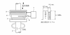
- Aluminum adhesion test uses the equipment shown in Fig. 4 (for example, Ribbon triboric) and places the ring (pressure ring) coaxially on a rotating shaft at a low speed and adjusts it to a predetermined temperature.
- the piston material AC8A material
- a surface pressure load is periodically generated between the ring and the piston material until aluminum adhesion occurs. If aluminum adhesion occurs, the torque of the rotating shaft fluctuates and the temperature also rises. The life is evaluated by the number of duty cycles at that time.
- the test conditions were a test temperature of 240 ° C, a contact pressure load touch width of 0 to 1.1 MPa, a contact pressure load cycle number of 3.3 Hz, a ring rotation speed of 3.3 m / sec (one-way rotation), and an additive-free base oil SAE30.
- a test temperature of 240 ° C a contact pressure load touch width of 0 to 1.1 MPa
- a contact pressure load cycle number 3.3 Hz
- a ring rotation speed 3.3 m / sec (one-way rotation)
- SAE30 additive-free base oil
Landscapes
- Chemical & Material Sciences (AREA)
- Engineering & Computer Science (AREA)
- Mechanical Engineering (AREA)
- Materials Engineering (AREA)
- Metallurgy (AREA)
- Organic Chemistry (AREA)
- Physics & Mathematics (AREA)
- Thermal Sciences (AREA)
- Crystallography & Structural Chemistry (AREA)
- General Engineering & Computer Science (AREA)
- Pistons, Piston Rings, And Cylinders (AREA)
Abstract
La présente invention concerne notamment un procédé visant à réaliser un segment de pression pouvant être utilisé dans l'environnement à forte charge thermique d'un moteur à fort taux de compression, caractérisé par une excellente conductivité thermique et une excellente résistance à la dégradation thermique, ainsi que par un prix compétitif. A cet effet, un acier désigné par le code de matériau SKS93 tel que stipulé par la norme JIS G 4404 est utilisé et la matière première en barres pour segments de piston est recuite avant un traitement de trempe à l'huile, et de la cémentite sphérique d'un diamètre moyen de 0,1 à 1,5 μm est répartie au sein de la matrice de martensite trempée.
Priority Applications (3)
| Application Number | Priority Date | Filing Date | Title |
|---|---|---|---|
| US14/128,459 US9599223B2 (en) | 2011-06-22 | 2012-06-21 | Compression ring and its production method |
| EP12801952.8A EP2725264B1 (fr) | 2011-06-22 | 2012-06-21 | Segment de pression et procédé pour sa fabrication |
| CN201280030936.8A CN103620275B (zh) | 2011-06-22 | 2012-06-21 | 压力环及其制造方法 |
Applications Claiming Priority (2)
| Application Number | Priority Date | Filing Date | Title |
|---|---|---|---|
| JP2011-138860 | 2011-06-22 | ||
| JP2011138860A JP5762843B2 (ja) | 2011-06-22 | 2011-06-22 | 圧力リング及びその製造方法 |
Publications (1)
| Publication Number | Publication Date |
|---|---|
| WO2012176834A1 true WO2012176834A1 (fr) | 2012-12-27 |
Family
ID=47422665
Family Applications (1)
| Application Number | Title | Priority Date | Filing Date |
|---|---|---|---|
| PCT/JP2012/065848 Ceased WO2012176834A1 (fr) | 2011-06-22 | 2012-06-21 | Segment de pression et procédé pour sa fabrication |
Country Status (5)
| Country | Link |
|---|---|
| US (1) | US9599223B2 (fr) |
| EP (1) | EP2725264B1 (fr) |
| JP (1) | JP5762843B2 (fr) |
| CN (1) | CN103620275B (fr) |
| WO (1) | WO2012176834A1 (fr) |
Families Citing this family (6)
| Publication number | Priority date | Publication date | Assignee | Title |
|---|---|---|---|---|
| JP2015108417A (ja) * | 2013-12-05 | 2015-06-11 | 株式会社リケン | 大型ピストンリング及びその素材並びにそれらの製造方法。 |
| RU2674177C2 (ru) | 2013-09-09 | 2018-12-05 | Ниссан Мотор Ко., Лтд. | Высокотеплопроводное поршневое кольцо для двигателя внутреннего сгорания |
| CN105543700A (zh) * | 2016-01-26 | 2016-05-04 | 安徽同盛环件股份有限公司 | 一种金属圆环件及其辗轧成形方法 |
| US11512777B2 (en) | 2018-04-26 | 2022-11-29 | Kabushiki Kaisha Riken | Piston ring |
| WO2020104438A1 (fr) * | 2018-11-20 | 2020-05-28 | Ks Kolbenschmidt Gmbh | Composition de matière pour un revêtement destiné à des pièces de moteurs à combustion interne |
| WO2023026621A1 (fr) * | 2021-08-24 | 2023-03-02 | 日本精工株式会社 | Roulement à rouleaux |
Citations (7)
| Publication number | Priority date | Publication date | Assignee | Title |
|---|---|---|---|---|
| JPS5845357A (ja) * | 1981-09-10 | 1983-03-16 | Hitachi Metals Ltd | ピストンリング材 |
| JPH03254304A (ja) * | 1990-02-28 | 1991-11-13 | Hitachi Metals Ltd | 耐摩耗複合ロール |
| JPH0625823A (ja) * | 1992-07-10 | 1994-02-01 | Kobe Steel Ltd | 耐ピッチング性に優れた浸炭鋼部品 |
| JP2002060888A (ja) * | 2000-08-17 | 2002-02-28 | Nisshin Steel Co Ltd | 打抜き加工用鋼板 |
| JP2002194500A (ja) * | 2000-12-26 | 2002-07-10 | Nippon Piston Ring Co Ltd | ピストンリング |
| JP2006097109A (ja) * | 2004-09-30 | 2006-04-13 | Jfe Steel Kk | 高炭素熱延鋼板およびその製造方法 |
| JP2009235561A (ja) | 2008-03-04 | 2009-10-15 | Nissan Motor Co Ltd | ピストンリング |
Family Cites Families (8)
| Publication number | Priority date | Publication date | Assignee | Title |
|---|---|---|---|---|
| US4581079A (en) * | 1985-03-27 | 1986-04-08 | Amax Inc. | Bearing steel |
| US5225007A (en) | 1990-02-28 | 1993-07-06 | Hitachi Metals Ltd. | Method for wear-resistant compound roll manufacture |
| JPH05230596A (ja) * | 1992-02-25 | 1993-09-07 | Hitachi Metals Ltd | ピストンリング材 |
| JPH06299296A (ja) * | 1993-04-15 | 1994-10-25 | Kobe Steel Ltd | 耐脱炭性に優れた高強度ばね用鋼 |
| JP3737952B2 (ja) * | 2001-02-16 | 2006-01-25 | 本田技研工業株式会社 | Cvtベルト用押しブロックおよびその製造方法 |
| JP4559959B2 (ja) * | 2004-11-30 | 2010-10-13 | 新日本製鐵株式会社 | 高強度ばね用鋼 |
| JP2007063584A (ja) | 2005-08-05 | 2007-03-15 | Sumitomo Electric Ind Ltd | オイルテンパー線およびその製造方法 |
| JP5028131B2 (ja) * | 2007-04-13 | 2012-09-19 | 花王株式会社 | ゲル化剤 |
-
2011
- 2011-06-22 JP JP2011138860A patent/JP5762843B2/ja not_active Expired - Fee Related
-
2012
- 2012-06-21 US US14/128,459 patent/US9599223B2/en not_active Expired - Fee Related
- 2012-06-21 WO PCT/JP2012/065848 patent/WO2012176834A1/fr not_active Ceased
- 2012-06-21 CN CN201280030936.8A patent/CN103620275B/zh not_active Expired - Fee Related
- 2012-06-21 EP EP12801952.8A patent/EP2725264B1/fr not_active Not-in-force
Patent Citations (7)
| Publication number | Priority date | Publication date | Assignee | Title |
|---|---|---|---|---|
| JPS5845357A (ja) * | 1981-09-10 | 1983-03-16 | Hitachi Metals Ltd | ピストンリング材 |
| JPH03254304A (ja) * | 1990-02-28 | 1991-11-13 | Hitachi Metals Ltd | 耐摩耗複合ロール |
| JPH0625823A (ja) * | 1992-07-10 | 1994-02-01 | Kobe Steel Ltd | 耐ピッチング性に優れた浸炭鋼部品 |
| JP2002060888A (ja) * | 2000-08-17 | 2002-02-28 | Nisshin Steel Co Ltd | 打抜き加工用鋼板 |
| JP2002194500A (ja) * | 2000-12-26 | 2002-07-10 | Nippon Piston Ring Co Ltd | ピストンリング |
| JP2006097109A (ja) * | 2004-09-30 | 2006-04-13 | Jfe Steel Kk | 高炭素熱延鋼板およびその製造方法 |
| JP2009235561A (ja) | 2008-03-04 | 2009-10-15 | Nissan Motor Co Ltd | ピストンリング |
Non-Patent Citations (1)
| Title |
|---|
| See also references of EP2725264A4 |
Also Published As
| Publication number | Publication date |
|---|---|
| US9599223B2 (en) | 2017-03-21 |
| JP5762843B2 (ja) | 2015-08-12 |
| CN103620275A (zh) | 2014-03-05 |
| US20140117626A1 (en) | 2014-05-01 |
| JP2013007404A (ja) | 2013-01-10 |
| CN103620275B (zh) | 2016-08-17 |
| EP2725264B1 (fr) | 2018-09-05 |
| EP2725264A1 (fr) | 2014-04-30 |
| EP2725264A4 (fr) | 2015-09-02 |
Similar Documents
| Publication | Publication Date | Title |
|---|---|---|
| JP5676146B2 (ja) | 圧力リング及びその製造方法 | |
| JP5497884B2 (ja) | ピストンリングとシリンダーライナの製造用窒化可能な鋼組成物 | |
| EP3168506A1 (fr) | Anneau de pression | |
| JP5762843B2 (ja) | 圧力リング及びその製造方法 | |
| JP5093010B2 (ja) | 熱間加工用金型 | |
| WO2017014139A1 (fr) | Segment de piston et procédé de fabrication pour ce dernier | |
| JP5695635B2 (ja) | 窒化可能なピストンリング | |
| JP5763260B2 (ja) | 圧力リング用線材及びその製造方法 | |
| JP5090257B2 (ja) | アルミ加工用金型に適した工具鋼およびアルミ加工用金型 | |
| JP6454103B2 (ja) | 圧力リング | |
| JP6313601B2 (ja) | ピストンリング及びその製造方法 | |
| JP5060083B2 (ja) | ピストンリングの製造方法 | |
| TWI800200B (zh) | 油環用線 | |
| JP3952328B2 (ja) | 耐スカッフィング性および加工性に優れたピストンリング材 | |
| WO2019087562A1 (fr) | Bague de pression, moteur à combustion interne, fil machine pour bague de pression, et procédé de fabrication de fil machine pour bague de pression | |
| JP4531448B2 (ja) | 金型の窒化方法 | |
| JP2002348639A (ja) | イオンプレーティング処理に適した疲労強度,耐熱へたり性に優れたピストンリング用鋼 | |
| JP2005314744A (ja) | ピストンリング用材料及びその材料を用いたピストンリング | |
| JPH1180910A (ja) | ピストンリング材における耐スカッフィング性および加工性の改善方法 |
Legal Events
| Date | Code | Title | Description |
|---|---|---|---|
| 121 | Ep: the epo has been informed by wipo that ep was designated in this application |
Ref document number: 12801952 Country of ref document: EP Kind code of ref document: A1 |
|
| WWE | Wipo information: entry into national phase |
Ref document number: 14128459 Country of ref document: US |
|
| NENP | Non-entry into the national phase |
Ref country code: DE |
|
| WWE | Wipo information: entry into national phase |
Ref document number: 2012801952 Country of ref document: EP |