WO2013011890A1 - Phosphore pour électroluminescence du type à dispersion et élément électroluminescent du type à dispersion - Google Patents
Phosphore pour électroluminescence du type à dispersion et élément électroluminescent du type à dispersion Download PDFInfo
- Publication number
- WO2013011890A1 WO2013011890A1 PCT/JP2012/067683 JP2012067683W WO2013011890A1 WO 2013011890 A1 WO2013011890 A1 WO 2013011890A1 JP 2012067683 W JP2012067683 W JP 2012067683W WO 2013011890 A1 WO2013011890 A1 WO 2013011890A1
- Authority
- WO
- WIPO (PCT)
- Prior art keywords
- phosphor
- particles
- fine particles
- dispersion type
- refractive index
- Prior art date
- Legal status (The legal status is an assumption and is not a legal conclusion. Google has not performed a legal analysis and makes no representation as to the accuracy of the status listed.)
- Ceased
Links
Images


Classifications
-
- C—CHEMISTRY; METALLURGY
- C09—DYES; PAINTS; POLISHES; NATURAL RESINS; ADHESIVES; COMPOSITIONS NOT OTHERWISE PROVIDED FOR; APPLICATIONS OF MATERIALS NOT OTHERWISE PROVIDED FOR
- C09K—MATERIALS FOR MISCELLANEOUS APPLICATIONS, NOT PROVIDED FOR ELSEWHERE
- C09K11/00—Luminescent materials, e.g. electroluminescent or chemiluminescent
- C09K11/02—Use of particular materials as binders, particle coatings or suspension media therefor
- C09K11/025—Use of particular materials as binders, particle coatings or suspension media therefor non-luminescent particle coatings or suspension media
-
- C—CHEMISTRY; METALLURGY
- C09—DYES; PAINTS; POLISHES; NATURAL RESINS; ADHESIVES; COMPOSITIONS NOT OTHERWISE PROVIDED FOR; APPLICATIONS OF MATERIALS NOT OTHERWISE PROVIDED FOR
- C09K—MATERIALS FOR MISCELLANEOUS APPLICATIONS, NOT PROVIDED FOR ELSEWHERE
- C09K11/00—Luminescent materials, e.g. electroluminescent or chemiluminescent
- C09K11/08—Luminescent materials, e.g. electroluminescent or chemiluminescent containing inorganic luminescent materials
- C09K11/58—Luminescent materials, e.g. electroluminescent or chemiluminescent containing inorganic luminescent materials containing copper, silver or gold
- C09K11/582—Chalcogenides
- C09K11/584—Chalcogenides with zinc or cadmium
Definitions
- the present invention relates to a phosphor for dispersion type electroluminescence (hereinafter referred to as dispersion type EL) and a dispersion type EL element using the phosphor.
- dispersion type EL dispersion type electroluminescence
- Sulfide phosphors especially ZnS (zinc sulfide) phosphors used in dispersive EL, are highly hygroscopic and react with O, O 2 , OH, etc. generated by the decomposition of H 2 O by applying an electric field repeatedly. As the operation time accumulates, the luminance decreases.
- Patent Document 1 discloses a method for water-resistant coating of phosphor particles relatively easily by drying a solution in which phosphor particles and an oxide are dispersed.
- a phosphor layer is provided with a coating layer, and the refractive index of the coating material and the binder resin material that disperses the phosphor is set to 65% or more of that of the phosphor to increase the light scattering property. It shows how to increase the extraction efficiency.
- the refractive index of the phosphor coating layer and the binder resin material must be almost the same as the refractive index of the phosphor, but usually as a binder resin
- the refractive index of the thermoplastic resin used is at most about 1.6, which is much lower than 2.4 of the ZnS phosphor, and even if high refractive index fine particles are dispersed in the binder resin as shown in the examples, the refractive index is Therefore, it is difficult to increase the light extraction efficiency to 2.4, and the expected light extraction efficiency cannot be improved.
- the present invention has been made to solve the above technical problem, and an object of the present invention is to provide a dispersed EL phosphor having excellent moisture resistance and high luminance.
- the dispersion type EL phosphor of the present invention is used by being dispersed in a binder resin, and emits visible light by applying an electric field, and has a particle size on the surface of the base particle. Is coated with oxide dielectric fine particles that are smaller than the wavelength of the visible light, have a refractive index similar to that of the base particles, and a relative dielectric constant higher than that of the base particles.
- ZnS particles having a central particle size of several tens of ⁇ m can be preferably used.
- the ZnS particles are particles obtained by adding a very small amount of an activator (for example, Cu) or a coactivator (for example, Cl) to ZnS alone.
- the oxide dielectric fine particles are made of a material having a particle size of 100 nm or less, a refractive index within a range of ⁇ 10% of the refractive index of the base particles 411, and a relative dielectric constant of 10 or more. Is preferred. Specific examples include ZrO 2 (zirconia) fine particles and TiO 2 (titania) fine particles.
- the dispersion type EL device of the present invention includes a light emitting layer formed by dispersing the dispersion type EL phosphor in a binder resin.
- FIG. 3A is a schematic diagram for explaining the extraction efficiency of light emitted inside the ZnS phosphor particles approximated to a sphere in the light emitting layer.
- FIG. 3B is a schematic diagram for explaining the extraction efficiency of light emitted inside the ZnS phosphor particles coated with ZrO 2 fine particles in the light emitting layer.
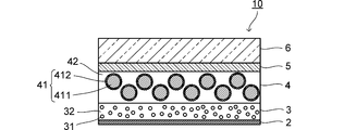
- a schematic configuration of a distributed EL element according to an embodiment of the present invention will be described with reference to FIG.
- a dispersion type EL element 10 shown in FIG. 1 is manufactured by sequentially laminating a light emitting layer 4, a dielectric layer 3 and a back electrode 2 on a transparent film 6 on which a transparent electrode 5 is formed.
- the top and bottom are shown inverted with respect to the stacking direction so that the light emitting surface is on the top.
- the transparent film 6 an arbitrary resin film having low moisture permeability and hygroscopicity can be used. However, since the heat resistance is good, a heat resistant resin film such as polyethylene terephthalate is particularly suitable. Regarding the film thickness, a film thickness of 0.30 mm or less is particularly preferable in order to improve the flexibility of the planar light emitter.
- the transparent electrode 5 is formed by depositing a transparent conductor such as ITO on the transparent film 6, for example, by sputtering.
- the light emitting layer 4 is made of a phosphor resin 41 uniformly dispersed in a binder resin 42 made of a thermoplastic resin.
- the phosphor 41 constituting the light emitting layer 4 is formed on the surface of the base particle 411, the particle size is smaller than the wavelength of the visible light, and the refractive index is the same as that of the base particle 411. It is characterized by being coated with oxide dielectric fine particles 412 having the same degree and a relative dielectric constant higher than that of the base particles.
- ZnS (zinc sulfide) particles having a center particle diameter of several tens of ⁇ m can be suitably used.
- the ZnS particles are particles obtained by adding a very small amount of an activator (for example, Cu) or a coactivator (for example, Cl) to ZnS alone.
- the oxide dielectric fine particles 412 preferably have a particle size of 100 nm or less, a refractive index within a range of ⁇ 10% of the refractive index of the base particles 411, and a relative dielectric constant of 10 or more.
- Specific examples include ZrO 2 (zirconia) fine particles and TiO 2 (titania) fine particles.
- the same material as the material of the binder resin 32 of the dielectric layer 3 described above can be used.
- the phosphor 41 is coated with a ZrO 2 fine particle (particle size of 100 nm or less) having a ZnS particle as a base particle 411.
- a ZrO 2 fine particle particle size of 100 nm or less
- fine particles of zirconium hydroxide or zirconia hydrate are precipitated on the surface of the phosphor particles by the urea precipitation method as shown in the following formulas (1) and (2), for example, as shown in the following formula (3).
- the phosphor 41 in which the surface of the base particle 411 is coated with the oxide dielectric fine particles 412 is mixed with a binder resin and a solvent to form a paste.
- the light emitting layer 4 is formed by applying the phosphor paste on the transparent electrode 5 with a uniform thickness by, for example, screen printing, and then baking.
- the dielectric layer 3 is formed by uniformly dispersing dielectric particles 31 in a binder resin 32 made of a thermoplastic resin.
- thermoplastic resin such as a fluororubber resin, a fluorine resin, an acrylic resin, a polypropylene resin, a polystyrene resin, or polyvinyl chloride is used. It is done.
- fine particles of BaTiO 3 (barium titanate) or rutile TiO 2 (titania) can be preferably used.
- a dielectric paste obtained by dispersing and mixing the dielectric particles 31 in a binder resin 32 dissolved in a solvent is applied on the light emitting layer 4 to a uniform thickness by, for example, screen printing. Then, it is formed by firing.
- the back electrode 2 is formed by vacuum-depositing a conductive metal material such as aluminum on the dielectric layer 3, for example.
- a conductive paste such as a silver paste can be screen-printed.
- the phosphor 41 constituting the light-emitting layer 4 is a ZrO 2 fine particle (particle size of 100 nm or less) that is a phosphor particle having ZnS particles as base particles 411 and oxide dielectric fine particles. ) Coated.
- the dielectric constant of ZrO 2 is about 30, which is higher than 8 of ZnS, 9 to 10 of Al 2 O 3 (alumina), and 10 to 15 of fluororesins frequently used as binder resins. Therefore, when the ZnS phosphor particles are coated with ZrO 2 fine particles, the electric field is more effectively applied to the ZnS phosphor particles, and the luminance of light emitted from the phosphor is improved.
- the refractive index of ZnS is 2.37, but the refractive index of binder resin is 1.6 at most.
- a model in which ZnS phosphor particles are approximated in a spherical shape as shown in FIG. 3A will be described.
- the light emitted inside the particle has an incident angle close to zero on the particle surface. Although incident light is emitted to the outside of the particle (see arrows 101 and 102), a significant portion of the light emission is confined inside the particle due to total reflection on the particle surface (see arrows 103 to 106).
- the refractive index of ZrO 2 is 2.4 and is very close to 2.37 of ZnS particles, in ZnS phosphor particles coated with ZrO 2 fine particles, as shown by arrows 201 and 203 in FIG. Light emission inside the particles enters the ZrO 2 fine particles from the phosphor almost without loss. Further, since the ZrO 2 fine particles are smaller than the wavelength of light, as indicated by arrows 202 and 204, the emitted light is emitted outside without being confined in the ZrO 2 fine particles, and the luminance is improved as compared with the case without the coating. Since the refractive index of Al 2 O 3 is about 1.7 and is close to that of the binder resin, such an effect cannot be expected with ZnS phosphor particles coated with Al 2 O 3 fine particles.
- dispersive EL element having excellent moisture resistance and increased emission luminance when coated with ZrO 2 fine particles, compared to the case without coating.
- ZnS phosphor particles having a central particle diameter of 20 ⁇ m using Cu as an activator were prepared. This was mixed with an aqueous solution of ZrOCl 2 (zirconium oxychloride) and urea and stirred while heating to about 80 ° C. to precipitate zirconia hydrate. The precipitate was then dried and calcined at 600 ° C. for 2.5 hours in an argon atmosphere. When the phosphor particles after firing were observed, the surface was covered with ZrO 2 fine particles having a particle diameter of 100 nm or less.
- ZrO 2 zirconium oxychloride
- the light emitting layer 4 is formed on the ITO transparent electrode film side of a PET film (transparent film 6) having an ITO (indium oxide) transparent electrode film (transparent electrode 5) formed on one side.
- the light emitting layer 4 is prepared by applying and baking a phosphor paste obtained by mixing the above phosphor with a binder resin at a weight ratio of 3: 1 on the transparent electrode 5 so that the film thickness after baking becomes about 80 ⁇ m.
- a film was formed.
- the dielectric layer 3 was formed by applying and baking a dielectric paste in which barium titanate particles and a fluorine-based resin were mixed at a weight ratio of 3: 1 on the light emitting layer 4 so that the film thickness after baking was 20 ⁇ m. .
- an Ag paste was applied on the dielectric 3 and baked to form the back electrode 2, thereby manufacturing the dispersion type EL element of Example 1.
- the dispersion type EL element of Comparative Example 1 uses uncoated ZnS phosphor particles before the phosphor constituting the light emitting layer 4 is coated with ZrO 2 fine particles. Are different. Other configurations are the same as those of the dispersion type EL element of the first embodiment.
Landscapes
- Chemical & Material Sciences (AREA)
- Engineering & Computer Science (AREA)
- Materials Engineering (AREA)
- Organic Chemistry (AREA)
- Inorganic Chemistry (AREA)
- Electroluminescent Light Sources (AREA)
- Luminescent Compositions (AREA)
Abstract
La présente invention concerne un phosphore pour électroluminescence du type à dispersion, ledit phosphore présentant une remarquable résistance à l'humidité et une luminance élevée. Ledit phosphore (4) pour électroluminescence du type à dispersion est obtenu par revêtement de la surface de particules de base (411) au moyen de fines particules (412) d'un matériau de type oxyde diélectrique. Les fines particules (412) du matériau de type oxyde diélectrique sont constituées d'un matériau présentant un diamètre inférieur aux longueurs d'onde de la lumière visible, un indice de réfraction à peu près identique à celui des particules de base (411) et une permittivité relative supérieure à celle des particules de base (411).
Applications Claiming Priority (2)
| Application Number | Priority Date | Filing Date | Title |
|---|---|---|---|
| JP2011-156310 | 2011-07-15 | ||
| JP2011156310 | 2011-07-15 |
Publications (1)
| Publication Number | Publication Date |
|---|---|
| WO2013011890A1 true WO2013011890A1 (fr) | 2013-01-24 |
Family
ID=47558068
Family Applications (1)
| Application Number | Title | Priority Date | Filing Date |
|---|---|---|---|
| PCT/JP2012/067683 Ceased WO2013011890A1 (fr) | 2011-07-15 | 2012-07-11 | Phosphore pour électroluminescence du type à dispersion et élément électroluminescent du type à dispersion |
Country Status (3)
| Country | Link |
|---|---|
| JP (1) | JPWO2013011890A1 (fr) |
| TW (1) | TW201309088A (fr) |
| WO (1) | WO2013011890A1 (fr) |
Cited By (2)
| Publication number | Priority date | Publication date | Assignee | Title |
|---|---|---|---|---|
| WO2024231492A1 (fr) * | 2023-05-11 | 2024-11-14 | Valeo Vision | Film électroluminescent mince, flexible et lumineux |
| FR3148675A1 (fr) * | 2023-05-11 | 2024-11-15 | Valeo Vision | Film électroluminescent mince, flexible et lumineux |
Families Citing this family (1)
| Publication number | Priority date | Publication date | Assignee | Title |
|---|---|---|---|---|
| TWI731616B (zh) * | 2020-03-09 | 2021-06-21 | 財團法人紡織產業綜合研究所 | 電致發光線 |
Citations (6)
| Publication number | Priority date | Publication date | Assignee | Title |
|---|---|---|---|---|
| JPH01284583A (ja) * | 1988-05-12 | 1989-11-15 | Mitsubishi Metal Corp | ZnS分散型EL蛍光体 |
| JPH09263753A (ja) * | 1996-03-29 | 1997-10-07 | Toshiba Corp | 蛍光体粒子の表面被覆方法 |
| JPH09272866A (ja) * | 1996-04-03 | 1997-10-21 | Toshiba Corp | 電場発光蛍光体およびその製造方法 |
| JP2003336046A (ja) * | 2002-05-17 | 2003-11-28 | Konica Minolta Holdings Inc | 無機蛍光体の表面処理方法及びそれを用いたディスプレイ素子 |
| JP2006052250A (ja) * | 2004-08-10 | 2006-02-23 | Fuji Photo Film Co Ltd | エレクトロルミネッセンス蛍光体、その製造方法、及びエレクトロルミネッセンス素子 |
| JP2006124680A (ja) * | 2004-09-29 | 2006-05-18 | Toda Kogyo Corp | 改質蛍光体粒子粉末、該改質蛍光体粒子粉末の製造法及び該改質蛍光体粒子粉末を用いたel素子 |
-
2012
- 2012-07-11 WO PCT/JP2012/067683 patent/WO2013011890A1/fr not_active Ceased
- 2012-07-11 JP JP2013524680A patent/JPWO2013011890A1/ja active Pending
- 2012-07-13 TW TW101125269A patent/TW201309088A/zh unknown
Patent Citations (6)
| Publication number | Priority date | Publication date | Assignee | Title |
|---|---|---|---|---|
| JPH01284583A (ja) * | 1988-05-12 | 1989-11-15 | Mitsubishi Metal Corp | ZnS分散型EL蛍光体 |
| JPH09263753A (ja) * | 1996-03-29 | 1997-10-07 | Toshiba Corp | 蛍光体粒子の表面被覆方法 |
| JPH09272866A (ja) * | 1996-04-03 | 1997-10-21 | Toshiba Corp | 電場発光蛍光体およびその製造方法 |
| JP2003336046A (ja) * | 2002-05-17 | 2003-11-28 | Konica Minolta Holdings Inc | 無機蛍光体の表面処理方法及びそれを用いたディスプレイ素子 |
| JP2006052250A (ja) * | 2004-08-10 | 2006-02-23 | Fuji Photo Film Co Ltd | エレクトロルミネッセンス蛍光体、その製造方法、及びエレクトロルミネッセンス素子 |
| JP2006124680A (ja) * | 2004-09-29 | 2006-05-18 | Toda Kogyo Corp | 改質蛍光体粒子粉末、該改質蛍光体粒子粉末の製造法及び該改質蛍光体粒子粉末を用いたel素子 |
Cited By (2)
| Publication number | Priority date | Publication date | Assignee | Title |
|---|---|---|---|---|
| WO2024231492A1 (fr) * | 2023-05-11 | 2024-11-14 | Valeo Vision | Film électroluminescent mince, flexible et lumineux |
| FR3148675A1 (fr) * | 2023-05-11 | 2024-11-15 | Valeo Vision | Film électroluminescent mince, flexible et lumineux |
Also Published As
| Publication number | Publication date |
|---|---|
| JPWO2013011890A1 (ja) | 2015-02-23 |
| TW201309088A (zh) | 2013-02-16 |
Similar Documents
| Publication | Publication Date | Title |
|---|---|---|
| JP6185481B2 (ja) | エレクトロルミネッセンスデバイス、およびその製造 | |
| EP1860919B1 (fr) | Élément d électroluminescence et appareil d éclairage | |
| JP2005302508A (ja) | 透明導電性シートおよびそれを用いたエレクトロルミネッセンス素子 | |
| JPWO2013011890A1 (ja) | 分散型el用蛍光体および分散型el素子 | |
| CN106538053A (zh) | 有机el发光装置 | |
| WO2014077422A1 (fr) | Film conducteur transparent et dispositif électroluminescent organique comprenant ce dernier | |
| JP4740582B2 (ja) | 電界発光装置 | |
| TWI673898B (zh) | 用於有機發光二極體之光萃取基板、製造其之方法、及包含其之有機發光二極體裝置 | |
| CN111286975A (zh) | 电致发光纤维 | |
| JP5744621B2 (ja) | 分散型el素子およびその製造方法 | |
| JP5647841B2 (ja) | 分散型el素子の製造方法 | |
| TWI704053B (zh) | 電致發光纖維 | |
| JP2010215787A (ja) | 無機蛍光体粒子およびそれを用いた分散型エレクトロルミネッセンス素子 | |
| JP4533775B2 (ja) | 電場発光蛍光体粒子および分散型エレクトロルミネッセンス素子 | |
| JP4515274B2 (ja) | 無機発光ディスプレイ | |
| JP2012064480A5 (fr) | ||
| JP5672940B2 (ja) | 無機エレクトロルミネッセンス用蛍光体粉末及びその製造方法、並びに分散型無機エレクトロルミネッセンス素子 | |
| JPH06309922A (ja) | 導電ペースト及び透光性導電膜 | |
| JP2006303030A (ja) | エレクトロルミネッセンス素子 | |
| JP2008210780A (ja) | 分散型el素子及びその製造方法 | |
| CN121152858A (zh) | 薄、柔性且发光的电致发光膜 | |
| JP5197653B2 (ja) | 分散型無機el素子、その製造方法および無機el発光層の製造装置 | |
| JP4769627B2 (ja) | 無機分散型エレクトロルミネッセンス素子 | |
| JP2000100571A (ja) | 分散型el素子 | |
| JP2006089594A (ja) | 電場発光蛍光体及びその製造方法、並びにエレクトロルミネッセンス素子 |
Legal Events
| Date | Code | Title | Description |
|---|---|---|---|
| 121 | Ep: the epo has been informed by wipo that ep was designated in this application |
Ref document number: 12815309 Country of ref document: EP Kind code of ref document: A1 |
|
| ENP | Entry into the national phase |
Ref document number: 2013524680 Country of ref document: JP Kind code of ref document: A |
|
| NENP | Non-entry into the national phase |
Ref country code: DE |
|
| 122 | Ep: pct application non-entry in european phase |
Ref document number: 12815309 Country of ref document: EP Kind code of ref document: A1 |