WO2013014708A1 - Dispositif de régulation d'humidité et système de climatisation - Google Patents
Dispositif de régulation d'humidité et système de climatisation Download PDFInfo
- Publication number
- WO2013014708A1 WO2013014708A1 PCT/JP2011/004238 JP2011004238W WO2013014708A1 WO 2013014708 A1 WO2013014708 A1 WO 2013014708A1 JP 2011004238 W JP2011004238 W JP 2011004238W WO 2013014708 A1 WO2013014708 A1 WO 2013014708A1
- Authority
- WO
- WIPO (PCT)
- Prior art keywords
- air
- desorption
- humidity
- moisture adsorption
- temperature
- Prior art date
- Legal status (The legal status is an assumption and is not a legal conclusion. Google has not performed a legal analysis and makes no representation as to the accuracy of the status listed.)
- Ceased
Links
Images




Classifications
-
- F—MECHANICAL ENGINEERING; LIGHTING; HEATING; WEAPONS; BLASTING
- F24—HEATING; RANGES; VENTILATING
- F24F—AIR-CONDITIONING; AIR-HUMIDIFICATION; VENTILATION; USE OF AIR CURRENTS FOR SCREENING
- F24F11/00—Control or safety arrangements
- F24F11/0008—Control or safety arrangements for air-humidification
-
- B—PERFORMING OPERATIONS; TRANSPORTING
- B01—PHYSICAL OR CHEMICAL PROCESSES OR APPARATUS IN GENERAL
- B01D—SEPARATION
- B01D53/00—Separation of gases or vapours; Recovering vapours of volatile solvents from gases; Chemical or biological purification of waste gases, e.g. engine exhaust gases, smoke, fumes, flue gases, aerosols
- B01D53/26—Drying gases or vapours
- B01D53/265—Drying gases or vapours by refrigeration (condensation)
-
- F—MECHANICAL ENGINEERING; LIGHTING; HEATING; WEAPONS; BLASTING
- F24—HEATING; RANGES; VENTILATING
- F24F—AIR-CONDITIONING; AIR-HUMIDIFICATION; VENTILATION; USE OF AIR CURRENTS FOR SCREENING
- F24F11/00—Control or safety arrangements
- F24F11/30—Control or safety arrangements for purposes related to the operation of the system, e.g. for safety or monitoring
-
- F—MECHANICAL ENGINEERING; LIGHTING; HEATING; WEAPONS; BLASTING
- F24—HEATING; RANGES; VENTILATING
- F24F—AIR-CONDITIONING; AIR-HUMIDIFICATION; VENTILATION; USE OF AIR CURRENTS FOR SCREENING
- F24F3/00—Air-conditioning systems in which conditioned primary air is supplied from one or more central stations to distributing units in the rooms or spaces where it may receive secondary treatment; Apparatus specially designed for such systems
- F24F3/12—Air-conditioning systems in which conditioned primary air is supplied from one or more central stations to distributing units in the rooms or spaces where it may receive secondary treatment; Apparatus specially designed for such systems characterised by the treatment of the air otherwise than by heating and cooling
- F24F3/14—Air-conditioning systems in which conditioned primary air is supplied from one or more central stations to distributing units in the rooms or spaces where it may receive secondary treatment; Apparatus specially designed for such systems characterised by the treatment of the air otherwise than by heating and cooling by humidification; by dehumidification
- F24F3/1411—Air-conditioning systems in which conditioned primary air is supplied from one or more central stations to distributing units in the rooms or spaces where it may receive secondary treatment; Apparatus specially designed for such systems characterised by the treatment of the air otherwise than by heating and cooling by humidification; by dehumidification by absorbing or adsorbing water, e.g. using an hygroscopic desiccant
-
- F—MECHANICAL ENGINEERING; LIGHTING; HEATING; WEAPONS; BLASTING
- F24—HEATING; RANGES; VENTILATING
- F24F—AIR-CONDITIONING; AIR-HUMIDIFICATION; VENTILATION; USE OF AIR CURRENTS FOR SCREENING
- F24F3/00—Air-conditioning systems in which conditioned primary air is supplied from one or more central stations to distributing units in the rooms or spaces where it may receive secondary treatment; Apparatus specially designed for such systems
- F24F3/12—Air-conditioning systems in which conditioned primary air is supplied from one or more central stations to distributing units in the rooms or spaces where it may receive secondary treatment; Apparatus specially designed for such systems characterised by the treatment of the air otherwise than by heating and cooling
- F24F3/14—Air-conditioning systems in which conditioned primary air is supplied from one or more central stations to distributing units in the rooms or spaces where it may receive secondary treatment; Apparatus specially designed for such systems characterised by the treatment of the air otherwise than by heating and cooling by humidification; by dehumidification
- F24F3/1411—Air-conditioning systems in which conditioned primary air is supplied from one or more central stations to distributing units in the rooms or spaces where it may receive secondary treatment; Apparatus specially designed for such systems characterised by the treatment of the air otherwise than by heating and cooling by humidification; by dehumidification by absorbing or adsorbing water, e.g. using an hygroscopic desiccant
- F24F3/1429—Air-conditioning systems in which conditioned primary air is supplied from one or more central stations to distributing units in the rooms or spaces where it may receive secondary treatment; Apparatus specially designed for such systems characterised by the treatment of the air otherwise than by heating and cooling by humidification; by dehumidification by absorbing or adsorbing water, e.g. using an hygroscopic desiccant alternatively operating a heat exchanger in an absorbing/adsorbing mode and a heat exchanger in a regeneration mode
-
- B—PERFORMING OPERATIONS; TRANSPORTING
- B01—PHYSICAL OR CHEMICAL PROCESSES OR APPARATUS IN GENERAL
- B01D—SEPARATION
- B01D53/00—Separation of gases or vapours; Recovering vapours of volatile solvents from gases; Chemical or biological purification of waste gases, e.g. engine exhaust gases, smoke, fumes, flue gases, aerosols
- B01D53/02—Separation of gases or vapours; Recovering vapours of volatile solvents from gases; Chemical or biological purification of waste gases, e.g. engine exhaust gases, smoke, fumes, flue gases, aerosols by adsorption, e.g. preparative gas chromatography
- B01D53/04—Separation of gases or vapours; Recovering vapours of volatile solvents from gases; Chemical or biological purification of waste gases, e.g. engine exhaust gases, smoke, fumes, flue gases, aerosols by adsorption, e.g. preparative gas chromatography with stationary adsorbents
- B01D53/0454—Controlling adsorption
-
- F—MECHANICAL ENGINEERING; LIGHTING; HEATING; WEAPONS; BLASTING
- F24—HEATING; RANGES; VENTILATING
- F24F—AIR-CONDITIONING; AIR-HUMIDIFICATION; VENTILATION; USE OF AIR CURRENTS FOR SCREENING
- F24F2110/00—Control inputs relating to air properties
- F24F2110/20—Humidity
Definitions
- the present invention relates to a humidity control device that performs indoor humidity control and an air conditioning system including the humidity control device.
- an air conditioner having a dehumidifying function see, for example, Patent Document 1
- an adsorbent that adsorbs moisture is supported.
- a humidity control apparatus for example, see Patent Document 2 including a heat exchanger in a refrigerant circuit is known.
- the air conditioner of Patent Document 1 includes a refrigerant circuit provided with an outdoor heat exchanger on the heat source side and an indoor heat exchanger on the use side, and performs a refrigeration cycle by circulating the refrigerant in the refrigerant circuit.
- the air conditioner dehumidifies the room by setting the refrigerant evaporation temperature in the indoor heat exchanger to be lower than the dew point temperature of the room air and condensing moisture in the room air.
- the humidity control apparatus of Patent Document 2 is provided with two heat exchangers adsorbed with an adsorbent, one of which is used as a high-pressure and high-temperature heat exchanger to desorb moisture, and the other is a low-pressure and low-temperature heat exchanger.
- the adsorption and desorption are repeated by switching the high and low pressure by inverting the circulation direction of the refrigerant by switching the four-way valve at a predetermined time interval.
- JP 2010-121912 (Claim 1, FIG. 1)
- the present invention has been made to solve the above-described problems, and a humidity control apparatus and an air that can control the amount of latent heat treatment and the amount of sensible heat treatment in accordance with the indoor heat load without lowering the operation efficiency.
- the aim is to obtain a harmonious system.
- a humidity control apparatus is provided in a main body having a suction port for sucking air from a dehumidification target space and a discharge port for supplying air to the dehumidification target space, and communicates the suction port and the discharge port.
- a first moisture adsorbing / desorbing device that is disposed in the air passage, releases air to relatively low humidity air, and absorbs moisture from relatively high humidity air; and first moisture in the air passage
- a cooling device that cools the air humidified by dehumidification of the first moisture adsorption / desorption device or the second moisture adsorption / desorption device, and disposed in the air path,
- the air sucked from the suction port is converted into the first moisture adsorption / desorption device, the cooling device, the second A switching device that switches alternately between a first air path that passes in the order of the partial adsorption / desorption device, and a second air path that passes in the order of the second moisture adsorption / desorption device, the cooling device, and the first moisture adsorption / desorption device; Every time the air path is switched to the first air path or the second air path, the path maintenance time of the switched air path is set based on the heat load in the dehumidification target space, and the set And a control device that controls switching of the switching device so as to be a route maintenance time.
- the amount of sensible heat treatment and the amount of latent heat treatment can be controlled by changing the balance between the sensible heat treatment capability and the latent heat treatment capability simply by changing the path maintenance time of the air path.
- FIG. 6 is a diagram illustrating the dry-bulb temperature until indoor air RA passes through various places in the humidity control device to become humidity control air SA (FIG. It is a figure which shows the relationship between the relative humidity of the adsorption agent used for the moisture adsorption / desorption apparatus of FIG. 1, and an equilibrium adsorption amount.
- FIG. 1 is a schematic diagram showing a configuration of a humidity control apparatus according to Embodiment 1 of the present invention.
- FIG. 2 is an explanatory diagram for explaining the flow of air in the humidity control apparatus of FIG. 1.
- FIG. 1, FIG. 2, and the figure mentioned later what attached
- the forms of the constituent elements appearing in the entire specification are merely examples and are not limited to these descriptions.
- the humidity control device 30 includes a main body 1 having a suction port 3 that sucks indoor air RA from a room that is a dehumidifying target space, and a discharge port 4 that supplies humidity control air SA to the room, and the suction port 3 and the discharge port 4.
- An air passage 2 through which air flows is provided in the communication interior, and moisture adsorption / desorption devices 33a and 33b that adsorb moisture contained in the air or desorb moisture into the air, and air
- a cooling device 32 that cools the air, an indoor air blower 35 (see FIG. 3 to be described later) that blows air in the air passage 2, and switching devices 34 a and 34 b that switch the path of the air flowing in the air passage 2.
- the humidity control device 30 includes a humidity control device control board 36.
- FIG. 2 (a) shows the air path A in FIG. 1
- FIG. 2 (b) shows the air path B in FIG.
- room air is sucked from the suction port 3
- room air is sucked from the suction port 3, passes through the moisture adsorption / desorption device 33 b, the cooling device 32, and the moisture adsorption / desorption device 33 a, passes through the indoor air blower 35, and enters the room as humidity control air from the discharge port 4. It is a route to be supplied.
- the air path A and the air path B are switched by the switching devices 34a and 34b.
- the first embodiment is characterized by this switching control, which will be described later.
- a damper or the like is used for the switching devices 34a and 34b, and although not shown, the air path is switched by controlling the motor rotation operation used for the damper operation.
- the air passage 2 has a structure in which a pipe connecting the suction port 3 and the discharge port 4 is branched in two directions.
- the switching device 34a is disposed at a location where this branch starts, and the switching device 34b is disposed at a location where the branch ends.
- the moisture adsorption / desorption device 33 a, the cooling device 32, and the moisture adsorption / desorption device 33 b are arranged so as to be sandwiched between the switching device 34 a and the switching device 34 b, and with respect to the air flow direction from the suction port 3 toward the discharge port 4.
- the air flows in a direction substantially perpendicular to the direction.
- the moisture adsorption / desorption devices 33a and 33b are porous flat plates having a polygonal cross section along the pipe cross section of the air passage 2 where the moisture adsorption / desorption devices 33a and 33b are arranged, so that a large cross sectional area can be obtained.
- the hole is formed so that air can pass in the thickness direction. Further, since the moisture adsorption / desorption devices 33a and 33b in the air passage 2 are arranged as described above, when the ventilation cross-sectional area is increased, the distance between the switching device 34a and the switching device 34b in the air passage 2 (FIG. 2).
- the cross-sectional area of the moisture adsorption / desorption devices 33a and 33b may be increased, and the size of the main body 1 in the width direction (vertical direction in FIG. 2) can be suppressed.
- the shape of the porous flat plate is not limited as long as the same effect can be obtained by forming the shape along the cross section of the pipe.
- the moisture adsorption / desorption devices 33a and 33b and the cooling device 32 are arranged so as to be substantially in series in the direction of air flow in either of the air routes A and B. It is provided between the desorption device 33a and the moisture adsorption / desorption device 33b.
- these moisture adsorption / desorption devices 33a and 33b and the cooling device 32 By disposing these moisture adsorption / desorption devices 33a and 33b and the cooling device 32 so that the surfaces through which the air passes are opposed to each other, these devices can be housed in a small space in the air passage 2, and the humidity control device 30 can be reduced in size.
- the facing may be slightly shifted in angle, and the same effect can be obtained.
- Moisture is adsorbed (moisture absorbed) from air with relatively high humidity on the surfaces of the porous flat plates constituting the moisture adsorption / desorption devices 33a and 33b, and moisture is desorbed (moisture released) with respect to air with relatively low humidity.
- adsorbents have an amount of moisture that can be adsorbed with respect to the relative humidity of air (equilibrium adsorption amount). If the adsorbent continues to adsorb moisture from air with a certain relative humidity and reaches an equilibrium adsorption amount, the adsorbent becomes in an equilibrium state and cannot absorb more moisture. Therefore, it is necessary to desorb moisture from the air so that it can be adsorbed again, and it is necessary to alternately repeat the adsorption operation and the desorption operation.
- the cooling device 32 is for the purpose of cooling the air that has passed through the moisture adsorption / desorption device 33a or the moisture adsorption / desorption device 33b to a dew point temperature or lower, increasing the relative humidity of the air, and removing moisture contained in the air as condensed water. Is provided. Although not shown, the moisture condensed by the cooling device 32 is drained out of the main body 1 by providing a drainage path, for example, as in a general humidity control device.
- an evaporator that is a low-temperature heat exchanger of a heat pump of a refrigeration cycle, a brine cooler, or the like is used.
- a brine cooler the brine cooled by the brine circuit is passed through the piping of the finned tube heat exchanger so that the air is cooled by passing through this heat exchanger. It has become.
- an evaporator is used, and an expansion valve 31 as an expansion device is connected to a pipe connected to the evaporator.
- temperature sensors 2a and 2b are connected to the pipes connected to the evaporator, and the opening degree of the expansion valve 31 is controlled by a humidity control device control board 36 described later based on temperature information measured by the temperature sensors 2a and 2b. Can be controlled to control the evaporation temperature of the evaporator.
- the indoor air blower 35 is composed of a fan or the like, and can set the air volume of the air flowing in the air passage 2 according to the air condition.
- a DC motor as the motor that rotates the fan
- the air volume is controlled by changing the current value and controlling the number of revolutions.
- the power supply frequency is changed by inverter control. By controlling the rotation speed, the air volume can be controlled.
- the flow rate of air passing through the moisture adsorption / desorption devices 33a and 33b also changes by controlling the air volume of the indoor blower 35.
- Adsorption and desorption speed of adsorbent used in the moisture adsorption / desorption devices 33a and 33b increases as the flow rate of air passing through the adsorbent increases.
- the adsorption / desorption capability of the adsorbent can be increased.
- the indoor air blower 35 is disposed on the most downstream side in the air passage 2.
- the indoor air blower 35 can be obtained from the arrangement position in FIG. It may be arranged upstream, for example, in the uppermost stream in the air passage 2, and may be arranged in plural, such as upstream and downstream, and the arrangement position and number of the indoor air blowers 35 are not limited.
- FIG. 3 is a control block diagram of the humidity control apparatus of FIG.
- the humidity control apparatus 30 has a controller 40 that accepts temperature and humidity setting operations and performs various controls.
- the temperature sensors 2 a and 2 b and the temperature and humidity sensor 3 a are connected to the controller 40. Then, the controller 40 performs control of the expansion valve 31, air volume control of the indoor air blower 35, switching control of the switching devices 34 a and 34 b, etc. via the humidity control device control board 36 based on sensor information from these sensors.
- FIG. 4 is a moist air diagram showing changes in the air state during operation of the humidity control apparatus of FIG.
- the vertical axis of the wet air diagram of FIG. 4 is the absolute humidity of the air
- the horizontal axis is the dry bulb temperature of the air.
- the curve in FIG. 4 has shown the saturation line (relative humidity 100%).
- the air states in the wet air diagram are indicated by (1) to (4), (1) to (4) in FIG. 2 (a), and (1) to (4) in FIG. 2 (b). ) Respectively.
- FIG. 4 the air states in the wet air diagram are indicated by (1) to (4), (1) to (4) in FIG. 2 (a), and (1) to (4) in FIG. 2 (b).
- FIG. 5 shows how the dry bulb temperature (dotted line in FIG. 5) and absolute humidity (solid line in FIG. 5) change until the room air RA passes through various places in the humidity control device to become the humidity control air SA.
- the horizontal axis represents the path
- the vertical axis represents the dry bulb temperature and the absolute humidity.
- FIG. The room air RA in the state (1) is introduced into the suction port 3 of the air passage 2 and flows into the moisture adsorption / desorption device 33a.
- the introduced air often has a relative humidity of 40 to 60%, and the moisture adsorption / desorption device 33a desorbs moisture according to the moisture content of the moisture adsorption / desorption device 33a at that time, in other words, Release moisture into the air.
- the air that has passed through the moisture adsorption / desorption device 33a is humidified, the dry bulb temperature decreases, and the absolute humidity increases, resulting in the state (2).
- the dew point temperature increases due to the increase in absolute humidity.
- the decrease in the dry bulb temperature is because the moisture adsorption / desorption device 33a undergoes an endothermic reaction at the time of desorption.
- the desorption temperature of the moisture adsorption / desorption device 33a is used to humidify the air to increase the dew point temperature, and then the moisture is condensed by the cooling device 32 that passes next. It is changed to an easy air condition.
- the air in the state (2) flows into the cooling device 32.
- the air that has flowed into the cooling device 32 is cooled below the dew point temperature when passing through the cooling device 32, and is in the state (3).
- the difference in moisture between the absolute humidity in the state (2) and the absolute humidity in the state (3) is condensed, and the air is dehumidified.
- the air becomes saturated air by this cooling, and the relative humidity of the air increases to about 100%.
- the air is dehumidified and the relative humidity of the air is increased, so that the moisture adsorbing / desorbing device 33b that passes next changes to an air state in which moisture is easily adsorbed. I am letting.
- the air in the state (3) flows into the moisture adsorption / desorption device 33b. Since the moisture adsorption / desorption device 33b adsorbs moisture from the air in accordance with the moisture content of the moisture adsorption / desorption device 33b at that time, the air passing through the moisture adsorption / desorption device 33b is dehumidified and the dry bulb temperature rises. At the same time, the absolute humidity is lowered to (4).
- the rise in dry bulb temperature is because the moisture adsorption / desorption device 33b performs a heat radiation reaction during adsorption.
- the humidity is dehumidified and supplied to the room by the adsorption reaction of the moisture adsorption / desorption device 33b.
- the air in the state (4) is supplied indoors as humidity-controlled air from the discharge port 4 of the air passage 2 via the indoor air blower 35.
- the room air in the state (1) is introduced into the suction port 3 of the air passage 2 and flows into the moisture adsorption / desorption device 33b.
- the introduced air often has a relative humidity of 40 to 60%, and the moisture adsorption / desorption device 33b desorbs moisture according to the moisture content of the moisture adsorption / desorption device 33b at that time, in other words, Release moisture into the air.
- the air that has passed through the moisture adsorption / desorption device 33b is humidified, and the dry bulb temperature is lowered and the absolute humidity is raised, resulting in the state (2).
- the dew point temperature increases due to the increase in absolute humidity.
- the decrease in the dry bulb temperature is because the moisture adsorption / desorption device 33b undergoes an endothermic reaction at the time of desorption.
- the air is humidified to increase the dew point temperature, and the moisture is condensed in the cooling device 32 that passes next. It is changed to an easy air condition.
- the air in the state (2) flows into the cooling device 32.
- the air that has flowed into the cooling device 32 is cooled below the dew point temperature when passing through the cooling device 32, and is in the state (3).
- the difference in moisture between the absolute humidity in the state (2) and the absolute humidity in the state (3) is condensed, and the air is dehumidified.
- the air becomes saturated air by this cooling, and the relative humidity of the air increases to about 100%.
- the air is dehumidified and the relative humidity of the air is increased, and the moisture adsorbing / desorbing device 33a that passes next changes to an air state in which moisture is easily adsorbed. I am letting.
- the air in the state (3) flows into the moisture adsorption / desorption device 33a. Since the moisture adsorption / desorption device 33a adsorbs moisture from the air in accordance with the moisture content of the moisture adsorption / desorption device 33a at that time, the air passing through the moisture adsorption / desorption device 33a is dehumidified and the dry bulb temperature rises. At the same time, the absolute humidity is lowered to (4). Here, the rise of the dry bulb temperature is because the moisture adsorption / desorption device 33a performs a heat radiation reaction during adsorption.
- the moisture is dehumidified by the adsorption reaction of the moisture adsorption / desorption device 33a and is changed to humidity-controlled air supplied to the room.
- the air in the state (4) is supplied indoors as humidity-controlled air from the discharge port 4 of the air passage 2 via the indoor air blower 35.
- the switching between the air path A and the air path B is performed by operating the switching devices 34a and 34b.
- the moisture adsorption / desorption device 33a that has been desorbing in the air path A is adsorbed in the air path B, and the moisture adsorption / desorption device in which the adsorption reaction is performed in the air path A. 33b will undergo a desorption reaction in the air path B.
- the adsorption and desorption are alternately performed by the switching operation of the switching devices 34a and 34b, so that the dehumidifying operation can be continuously performed.
- the amount of equilibrium adsorption at a relative humidity of 80 to 100% (the amount of moisture that can be adsorbed with respect to the relative humidity of air) is large.
- An adsorbent having a large difference from the equilibrium adsorption amount at a relative humidity of 40 to 60% is used.
- FIG. 6 is a diagram showing the relationship between the relative humidity of the adsorbent used in the moisture adsorption / desorption apparatus of FIG. 1 and the equilibrium adsorption amount.
- the vertical axis is the equilibrium adsorption amount, and the horizontal axis is the relative humidity.
- the solid curve (a) shows the characteristics of the adsorbent used in the moisture adsorption / desorption devices 33a and 33b, and the broken curve (b) shows the characteristics of another adsorbent for comparison.
- the adsorbent used in the moisture adsorption / desorption devices 33a and 33b has an approximately linear increase in the amount of equilibrium adsorption with respect to air having a relative humidity of 40 to 100%, resulting in a high humidity region (relative humidity of 80 to 100). %) Has a particularly large amount of equilibrium adsorption. That is, by increasing the relative humidity difference between the air passing through the adsorption and desorption of the moisture adsorption / desorption devices 33a and 33b, the difference in the equilibrium adsorption amount also increases, and the adsorption and desorption capability can be increased.
- the adsorbent shown as a comparative example shows little increase in the amount of equilibrium adsorption with increasing relative humidity. Therefore, when dehumidifying general indoor air (relative humidity of 40 to 60%) using the adsorbent of the comparative example, a difference is produced in the equilibrium adsorption amount of air passing during adsorption and desorption. Therefore, it is necessary to provide a desorption heat source such as a heating device to heat the air before desorption, and to reduce the relative humidity of the air to about 20%.
- a desorption heat source such as a heating device to heat the air before desorption, and to reduce the relative humidity of the air to about 20%.
- the adsorbent having a particularly high equilibrium adsorption amount in the high humidity region (relative humidity 80 to 100%) is used for the moisture adsorption / desorption devices 33a and 33b, air in a general indoor space (relative humidity 40 to A sufficient difference from the equilibrium adsorption amount at about 60%) can be obtained. Therefore, by using an adsorbent having such characteristics, a dehumidifying operation can be performed without a desorption heat source in the air passage 2.
- adsorbent having such characteristics include a cross-linked sodium polyacrylate in an organic system and a nanotube silicate (imogolite) and an aluminum silicate (husclay) in an inorganic system.
- imogolite nanotube silicate
- husclay aluminum silicate
- the first embodiment is characterized in the switching control of the air paths A and B by the switching devices 34a and 34b as described above.
- the switching control the heat treatment capability in the humidity control apparatus 30 will be explained.
- the room is cooled by an air conditioner different from the humidity control device 30 and the same space is dehumidified by the humidity control device 30.
- FIG. 7 is a diagram showing changes in the input and heat treatment amount when the path maintenance time Tda is extended.
- the horizontal axis shows the path maintenance time Tda, and the vertical axis shows the input and heat treatment capacity.
- the input is input power in a refrigeration cycle including an evaporator that constitutes the cooling device 32.
- the heat treatment amount includes a latent heat treatment amount, a sensible heat treatment amount, and a total heat treatment amount.
- the amount of latent heat treatment is the amount of capacity that can change the humidity of the air to be treated
- the amount of sensible heat treatment is the amount of ability that can change the temperature of the air to be treated
- the total amount of heat treatment is the amount of latent heat treatment It is the sum of the amount and the amount of sensible heat treatment.
- the humidity control apparatus 30 has a characteristic that the sensible heat treatment amount increases and the latent heat treatment amount decreases as the path maintaining time Tda is lengthened. That is, for example, when the air path A is continued for the initial setting time Tdas and when it is further extended, the amount of sensible heat treatment increases and the amount of latent heat treatment decreases. Further, FIG. 7 shows that the balance between the sensible heat treatment amount and the sensible heat treatment amount changes according to the path maintaining time Tda even if the input remains constant.
- the reason why the latent heat treatment amount and the sensible heat treatment amount change according to the path maintaining time Tda will be described in detail.
- the path maintenance time Tda is lengthened, the adsorbent is saturated and no adsorption reaction occurs, and no desorption reaction occurs on the desorption side, and only the cooling device 32 takes time for heat treatment.
- a time during which no desorption reaction occurs in the moisture adsorption / desorption device 33a and no adsorption reaction occurs in the moisture adsorption / desorption device 33b occurs.
- the desorption reaction does not occur in the moisture adsorption / desorption device 33a
- the dew point temperature of the air after passing through the moisture adsorption / desorption device 33a does not rise, so that it is not possible to create a state in which moisture is likely to be condensed in the cooling device 32 that passes next. . Therefore, the dehumidification amount decreases. For this reason, comparing the state immediately after the path switching with the state close to the saturated state, the amount of latent heat treatment is smaller in the state close to the saturated state.
- the sensible heat treatment amount increases for the following reason.
- the case of the air path A will be described.
- the moisture adsorption / desorption device 33a undergoes a heat release reaction during adsorption, but the heat release reaction becomes weaker as it approaches a saturated state. Therefore, comparing the state immediately after the path switching with the state close to the saturation state, the amount of sensible heat treatment increases in the state close to the saturation state.
- the temperature and humidity differ between the air passing through the cooling device 32 at the initial switching of the air path and the air passing through the cooling device 32 after the adsorbent is saturated, but the enthalpy of air is substantially the same. This is because air temperature and humidity change along substantially the same enthalpy line during the adsorption and desorption reaction of air and the adsorbent. Therefore, each of the latent heat treatment amount and the sensible heat treatment amount changes according to the path maintenance time, but the total heat treatment amount does not change. This point will be described with reference to FIG.
- the humidity-controlled air SA is in the state (4) immediately after the path is switched, but as the moisture adsorption / desorption devices 33a and 33b become saturated, the state approaches the state (3) and finally reaches a saturated state. Then, the state (3) is obtained.
- the state (3) has a lower dry bulb temperature and a higher absolute humidity than the humidity-conditioned air SA in the state (4) immediately after the path switching. Therefore, as the route maintenance time Tda becomes longer, humid air that is wetter and cooler than immediately after the route switching is supplied to the room. Therefore, when the path maintenance time Tda is lengthened, the speed of cooling the room is increased and the speed of decreasing the humidity is decreased rather than switching the air path in a short time.
- the route maintenance time Tda is shortened and the air route is switched quickly to reduce the indoor temperature Tra quickly.
- the air route may be switched after the route maintenance time Tda is lengthened and the operation in a state where the sensible heat treatment capability is high is performed for a long time.
- FIG. 8 is a control flowchart in the humidity control apparatus according to Embodiment 1 of the present invention.
- FIG. 8A is a flowchart of the route maintenance time setting process of FIG.
- a case where the room is cooled by an indoor unit of an air conditioner provided separately from the humidity control apparatus 30 and the humidity control apparatus 30 is operated for indoor humidity control will be described as an example.
- the control flowchart of FIG. 8 has shown the flow of the process started immediately after switching of an air path
- route Here, first, description will be made assuming that the state is switched to the state of the air path A.
- the cooling capacity of the cooling device 32 is assumed to be constant.
- the humidity control apparatus 30 starts operation when the humidity is higher than the set humidity.
- the indoor temperature Tra is equal to or higher than the set temperature Tm at the start of operation
- the operation is performed with priority given to lowering the indoor temperature Tra to the set temperature Tm rather than lowering the humidity to the set humidity.
- This is because humans have a property that they feel comfortable even when the humidity is high as long as the room temperature is appropriate. Therefore, when the indoor temperature is high, priority is given to the sensible heat load process, so that the indoor environment can be quickly made comfortable.
- the humidity controller 30 performs an operation that prioritizes the processing of the sensible heat load over the latent heat load when the room temperature Tra is equal to or higher than the set temperature Tm.
- an operation that gives priority to the latent heat load process is performed.
- the indoor latent heat load process is not necessarily performed, and it goes without saying that the latent heat load process is also performed simultaneously with the sensible heat load process.
- the humidity control apparatus 30 stops the operation.
- the room temperature Tra is set to be equal to or higher than the set temperature Tm.
- the present invention is not limited to this.
- the room temperature Tra is a predetermined temperature higher than the set temperature Tm. As mentioned above, it is good also as a high case.
- the indoor absolute humidity AHra can be calculated from the measurement result of the temperature / humidity sensor 3a, and the set absolute humidity AHm can be calculated from the indoor set temperature Tm and the set relative humidity set by a controller (not shown).
- the humidity control operation is started (S2). That is, while operating the indoor air blower 35 arrange
- the operation of the cooling device 32 corresponds to controlling the opening degree of the expansion valve 31 to flow a refrigerant having a set evaporation temperature into the cooling device 32, thereby cooling the air passing through the cooling device 32. be able to.
- the humidity control operation is stopped, that is, the operation of the indoor air blower 35 and the cooling device 32 is stopped (S3).
- the humidity control apparatus 30 performs a process of setting the path maintenance time Tda of the air path A (S4).
- the process for setting the route maintenance time Tda will be described with reference to FIG. 8A.
- the indoor set temperature Tm set from the outside by the controller 40 is compared with the indoor temperature Tra obtained from the measurement result of the temperature / humidity sensor 3a (S41). If the room temperature Tra is lower than the set temperature Tm, it is determined that the processing of the indoor latent heat load is prioritized, and the path maintaining time Tda is set to the initial set time Tda (S42).
- the extension time ⁇ T is determined for the purpose of making the path maintaining time Tda longer than the initial set time Tda so that the room temperature Tra can be brought closer to the set temperature Tm. (S43).
- This extended time ⁇ T is determined based on the time taken from the present time until the adsorbent is saturated (hereinafter referred to as the remaining saturation time).
- the remaining saturation time is determined as the extension time ⁇ T.
- the remaining saturation time varies depending on the current humidity of the room air and the cooling capacity of the cooling device 32, and depends on the refrigerant evaporation temperature flowing through the cooling device (here, the evaporator) 23 and the measurement result of the temperature / humidity sensor 3a. It can be calculated from the temperature and humidity of a certain air. Then, a time Tda + ⁇ T obtained by adding the extension time ⁇ T to Tda (initial setting time Tda for the first time) is set as the route maintenance time Tda (S44).
- the humidity control apparatus 30 maintains the air path A for the path maintaining time Tda set as described above (S5), and then switches the air path to the air path B.
- Tda set as described above
- the humidity control apparatus 30 maintains the air path A for the path maintaining time Tda set as described above (S5), and then switches the air path to the air path B.
- one cycle of processing for the air path A is completed. And it returns to step S1 again and performs the process similar to the above about air path B next.
- the initial setting time Tdas is 10 minutes here.
- the indoor absolute humidity AHra and the set absolute humidity AHm are compared (S1).
- the indoor air blower 35 and the cooling device 32 are compared.
- the operation is started (S2). Thereby, indoor temperature control and humidity control are started.
- the extension time ⁇ T is determined (S43).
- the saturation remaining time is calculated as 21 minutes, for example, 1/3 of 7 minutes is determined as the extension time ⁇ T, and the extension time 7 minutes is added to the initial setting time Tdas to obtain the path maintenance time Tda.
- the route maintaining time Tda is extended from the initial set time Tda of 10 minutes, so that the room temperature Tra is set to 10 minutes of the initial set time Tda.
- the sensible heat load can be positively treated, and the room temperature Tra can be quickly lowered.
- the extension time ⁇ T determined from the remaining saturation time determined according to the current indoor environment or the like is added to the previously determined route maintenance time Tda, so that the route maintenance after ⁇ T addition is performed.
- the time Tda may exceed the remaining saturation time.
- Exceeding the saturation remaining time means that the operation is continued in a state where the moisture adsorption / desorption devices 33a and 33b are saturated, but there is no problem even if the saturation remaining time is exceeded.
- Continuing the operation in a state where the moisture adsorption / desorption devices 33a and 33b are saturated corresponds to a state where the sensible heat treatment capability is high for a long time, and the sensible heat load can be quickly processed.
- the operation may be continued in a state where the moisture adsorption / desorption devices 33a and 33b are saturated in order to positively handle the sensible heat load.
- the route maintenance time Tda after addition of ⁇ T exceeds the saturation remaining time, the route maintenance time Tda may be limited to the saturation remaining time to avoid continuing the operation in the saturation state. Which control is used is arbitrary.
- the humidity control device 30 switches the air route to the air route B (S6), and returns to step S1.
- step S1 judgment of step S1 is performed, it is judged as YES here and operation
- step S4 the process for setting the route maintenance time Tda of the air route B is started (S4).
- the room temperature Tra is still equal to or higher than the set temperature Tm (S41)
- the remaining saturation time is first calculated to determine the extension time ⁇ T of the air path B.
- the saturation remaining time different from the previous time is calculated due to the change in the room temperature Tra and the absolute humidity AHra due to the humidity adjustment operation in the air path A performed until the present time. Then, for example, it is assumed that it is calculated as 30 minutes.
- the humidity control apparatus 20 determines ⁇ T as 10 minutes (S43). Then, 27 minutes obtained by adding 10 minutes of ⁇ T to 17 minutes of the route maintenance time Tda in the previous air route A is set as the route maintenance time Tda of the air route B (S44), and the operation in the air route B is performed. Is continued for 27 minutes (S5).
- the room temperature Tra can be lowered more quickly by extending the route maintenance time Tda of the air path B further than in the previous air path A.
- step S1 judgment of step S1 is performed, it is judged as YES here and the driving
- the path maintenance time Tda is set to The initial setting time Tdas is returned to 10 minutes, and the operation in the air path A is performed for 10 minutes.
- steps S2 to S6 are repeated while the indoor absolute humidity AHra is higher than the set absolute humidity AHm.
- the operation of the humidity control device 30 itself is stopped. That is, the operation of the indoor blower 35 and the cooling device 32 is stopped (S3).
- the sensible heat treatment amount and the latent heat treatment amount are controlled by changing the balance between the sensible heat treatment capability and the latent heat treatment capability only by changing the path maintenance time Tda of the air path. Can do. For this reason, when it is desired to increase the latent heat treatment capacity and increase the dehumidification amount, the operating frequency of the compressor of the refrigeration cycle is increased, the evaporation temperature is decreased, and the refrigerant flow in the refrigerant circuit is reduced. The operation of reversing is not necessary. Therefore, it becomes possible to control the air conditioning capability according to the set temperature and humidity without destroying the stability of the refrigeration cycle. Therefore, it is possible to suppress the inconvenience that the capacity does not appear until the refrigeration cycle is stabilized and the uncomfortable state continues for a long time, and the indoor environment can be quickly reached the target environment.
- the path maintenance time Tda when processing the indoor latent heat load with priority, the path maintenance time Tda is set to the preset initial setting time Tda, and the sensible heat load is processed with priority. In such a case, a time that is longer than the initial setting time Tda may be set as the route maintenance time Tda.
- the extension time ⁇ T is determined based on the remaining saturation time, the time required to reach the target temperature and humidity can be shortened.
- the air path is switched every time the air path is switched for the purpose of positively processing the sensible heat load.
- the operation for sequentially extending the route maintenance time Tda was performed. Thereby, for example, when the initial setting time Tdas is 10 minutes, after maintaining the air path A for 20 minutes, compared with the case where the air path B is maintained again for 20 minutes, the time until the target temperature and humidity are reached. Time can be shortened.
- the path maintenance time Tda is initialized to the initial set time Tda, so that the sensible heat treatment capability can be immediately increased, Time to reach humidity can be shortened.
- the sensible heat treatment capability can be immediately increased by initializing to the initial setting time Tdas. Therefore, the time until the target humidity is reached can be shortened.
- the present invention is not necessarily limited to this method, and the path is stepwise.
- the case where the maintenance time Tda is shortened is also included.
- the humidity control device 30 sets the indoor absolute humidity AHra when the indoor temperature Tra is equal to or higher than the set temperature Tm. Control is performed with priority given to lowering the indoor temperature Tra to the set temperature Tm rather than lowering to the humidity AHm. Therefore, the indoors can be comfortably quickly after the humidity control operation is started, compared with the case where control is given priority to lowering the humidity. Environment.
- the humidity control apparatus 30 uses a moisture adsorption / desorption apparatus using an adsorbent having a large adsorption equilibrium adsorption amount in a high humidity region as shown in FIG. Desorption is possible only by the difference between the moisture content of the device 33a or 33b and the equilibrium adsorption amount determined by the air relative humidity. That is, desorption without a desorption heat source such as a heating device is possible, the desorption heat source can be omitted, and the apparatus can be downsized.
- the cooling device 32 since the desorption is performed without a desorption heat source such as a heating device, the cooling device 32 does not need to process the amount of heat obtained by the passing air by the desorption heat source, so only the heat treatment of the return air RA is performed. It becomes energy saving.
- the temperature difference between the moisture adsorption / desorption device 33a and the moisture adsorption / desorption device 33b when the air path is switched is reduced, and the temperature of the moisture adsorption / desorption devices 33a and 33b and the moisture adsorption / desorption device are reduced.
- the temperature difference from the air temperature passing through 33a and 33b is also reduced. For this reason, the thermal resistance of the adsorbent generated by the temperature difference from the passing air in the moisture adsorption / desorption devices 33a and 33b is reduced, and the dehumidification operation can be performed with high efficiency.
- the moisture adsorption / desorption devices 33a and 33b and the cooling device 32 are arranged so as to be substantially in series in the direction of air flow in either of the air routes A and B. It is provided between the desorption device 33a and the moisture adsorption / desorption device 33b.
- these moisture adsorption / desorption devices 33a and 33b and the cooling device 32 By disposing these moisture adsorption / desorption devices 33a and 33b and the cooling device 32 so that the surfaces through which the air passes are opposed to each other, these devices can be housed in a small space in the air passage 2, and the humidity control device 30 can be reduced in size.
- the facing may be slightly shifted in angle, and the same effect can be obtained.
- the adsorption and desorption rate of the adsorbent used in the moisture adsorption / desorption devices 33a and 33b has temperature dependence in addition to wind speed dependence. The higher the is, the higher the adsorption and desorption speed.
- FIG. 9 shows the relationship between the passing air speed of the adsorbent used in the moisture adsorption / desorption apparatus and the adsorption / desorption speed.
- the vertical axis in FIG. 6 is the adsorption and desorption speed of the adsorbent, and the horizontal axis is the passing air velocity of the air passing through the adsorbent.
- T1 and T2 are temperatures of air passing through the adsorbent at the time of adsorption or desorption, and T1 is higher than T2, and T1 having a higher temperature has a higher adsorption and desorption rate.
- T1 is the air temperature at the time of desorption
- T2 is the air temperature at the time of adsorption
- dehumidifying operation is performed at a certain wind speed
- T1 and T2 there is a temperature difference between T1 and T2
- T1 and T2 so there is a difference between the time of desorption and the time of adsorption. Differences in adsorption and desorption rates occur.
- the total amount of moisture moving between the adsorbent and the air during adsorption and desorption is balanced at the slower adsorption and desorption speed.
- the humidity control apparatus of the first embodiment Since the humidity control apparatus of the first embodiment is not heated at the time of desorption, the difference in the air temperature between adsorption and desorption is smaller than when there is a heating apparatus, and the difference between the adsorption speed and the desorption speed is small. . For this reason, the adsorption and desorption rates are nearly uniform with each other, and the potential of the adsorbent can be used with high efficiency.
- the moisture adsorption / desorption devices 33a, 33b are fixed in the air passage 2 and are stationary, there is no limitation on the shape that occurs due to operation such as rotation like a desiccant rotor, and the moisture adsorption / desorption devices 33a, 33b, It is possible to match the ventilation area of 33b with the shape of the air path 2. And it is possible to secure a large ventilation area, reduce the wind speed, reduce the pressure loss, increase the contact area of the adsorbent of the moisture adsorption / desorption devices 33a, 33b with the air, and increase the adsorption / desorption amount. It becomes.
- the moisture adsorption / desorption devices 33a and 33b can reverse the air inflow direction at the time of adsorption and at the time of desorption, and the ventilation direction at the time of adsorption and desorption is reversed, so that the dehumidification / humidification efficiency can be increased.
- the air volume when passing through the humidity control device 30 temporarily changes, but the operating time of the switching devices 34a and 34b is the rotational speed of the motor used for the switching devices 34a and 34b. It is possible to make it sufficiently short with respect to the cycle of the air path switching, for example, by increasing. Therefore, the air paths A and B can be switched without affecting the refrigeration cycle.
- the desorption heat source is not provided.
- the desorption heat source may be provided.
- Embodiment 2 an air conditioning system that performs air conditioning of the same space using the humidity control device 30 of the first embodiment and an indoor unit that performs temperature control will be described.
- the humidity control device 30 and the indoor unit are connected by a single refrigerant circuit to form an air conditioning system, and the humidity control is performed by an evaporator that is a low-temperature side heat exchanger of the refrigerant circuit.
- the cooling device 32 of the device 30 is configured will be described.
- the second embodiment will be described focusing on the differences from the first embodiment. Note that the modification applied to the same components in the second embodiment as those in the first embodiment is similarly applied to the second embodiment. This also applies to the embodiments described later.
- FIG. 10 is a diagram showing a configuration of an air conditioning system according to Embodiment 2 of the present invention.
- the air conditioning system 100 includes an outdoor unit 10a, an indoor unit 10b, a humidity control device 30, and a controller 40A.
- Each of the indoor unit 10b and the humidity control apparatus 30 is connected to the liquid side main pipe 102 and the gas side main pipe 103 extending from the outdoor unit 10a via a branch pipe, and is connected in parallel to the outdoor unit 10a.
- the outdoor unit 10 a is connected to each of the indoor unit 10 b and the humidity control device 30 by the transmission line 101.
- the outdoor unit 10a and the controller 40A are also connected by the transmission line 101.
- the number of connected indoor units 10b and humidity control devices 30 is one each, but the number of connected units may be individually changed according to the outdoor functional force and the required dehumidification amount, and the number is not limited. . This also applies to the embodiments described later. Further, since the humidity control device 30 is the same as that of the first embodiment, description of the sensor arrangement on the air flow path side, the operation description on the air circuit side, the system control method, etc. in the humidity control device 30 is omitted. This also applies to the embodiments described later.
- FIG. 11 is a refrigerant circuit diagram of the air-conditioning system according to Embodiment 2 of the present invention.
- an inverter-driven variable capacity compressor 11, a cooling / heating switching four-way valve 13, an outdoor heat exchanger 12, and an accumulator 14 are provided in the outdoor unit 10a.
- the indoor unit 10b is provided with an expansion valve 21 and an indoor heat exchanger 22 that are capable of pulse-controlling the valve opening using a stepping motor.
- the expansion valve 21 and the indoor heat exchanger 22 of the indoor unit 10b, and the expansion valve 31 and the cooling device 32 of the humidity control device 30 are connected in parallel to the outdoor unit 10a.
- the four-way valve 13, the outdoor heat exchanger 12, the expansion valves 21 and 31, the indoor heat exchangers 22 and 32, and the accumulator 14 are sequentially connected to form a refrigerant circuit.
- the heating operation of the refrigeration cycle will be described with reference to FIG.
- the four-way valve 13 is switched to the dotted line side in FIG.
- the refrigerant discharged from the compressor 11 branches from the gas side main pipe 103 to the gas side branch pipe 105 from the four-way valve 13 and flows into the indoor heat exchangers 22 and 32.
- the refrigerant that has flowed into the indoor heat exchangers 22 and 32 is condensed and liquefied when heat is exchanged with the air, is decompressed by the expansion valves 21 and 31, and flows to the liquid side main pipe 102.
- the low-pressure refrigerant flows through the outdoor heat exchanger 12, exchanges heat with air, evaporates, passes through the four-way valve 13 and the accumulator 14, and is sucked into the compressor 11 again.
- the refrigerant used in the refrigerant circuit is not limited.
- Natural refrigerant such as carbon dioxide, hydrocarbon or helium
- Chlorine-free refrigerant such as HFC410A or HFC407C
- Existing Fluorocarbon refrigerants such as R22 or R134a used in products.
- various types such as a reciprocating machine, a rotary, a scroll, or a screw, are applicable to fluid apparatuses, such as a compressor which circulates this refrigerant
- the outdoor air blower 15 and the indoor air blowers 23 and 35 can control the air volume.
- the air volume can be set according to the air condition.
- the air volume control can be realized by changing the rotation speed by using a DC motor as a motor for rotating the fan, or by changing the power supply frequency by inverter control using an AC motor.
- the air volume control is performed by the controller 40A.
- the outdoor unit 10a includes an outdoor blower 15 (see FIG. 12 described later) for allowing air to pass through the outdoor heat exchanger 12.
- the outdoor unit 10 a includes a discharge pressure sensor 1 a on the discharge side of the compressor 11, a suction pressure sensor 1 b on the suction side, and an outdoor temperature sensor 2 c on the air suction side of the outdoor heat exchanger 12.
- the outdoor unit 10a further includes an outdoor unit control board 16, acquires sensor information from each sensor installed in the outdoor unit 10a, controls the rotational speed of the compressor 11 based on the information, and the outdoor blower 15 air volume control is performed.
- a controller 40A is connected to the outdoor unit control board 16 so as to receive an operation control signal from the controller 40A such as the start of cooling operation.
- the indoor unit 10b includes an indoor blower (not shown) for allowing air to pass through the indoor heat exchanger 22, and sucks air from the room and allows the air to pass through the indoor heat exchanger 22 to adjust the temperature. After going, blow into the room.
- the indoor unit 10b includes a liquid pipe temperature sensor 2a, a gas pipe temperature sensor 2b, and an intake air temperature sensor 2d that detects the temperature on the air intake side of the indoor heat exchanger 22.
- the indoor unit 10b further includes an indoor unit control board 24, acquires sensor information from each sensor installed in the indoor unit 10b, and controls the expansion valve 21 based on those information. Further, a controller 40A is connected to the indoor unit control board 24 so as to receive an operation control signal from the controller 40A such as the start of cooling operation.
- FIG. 12 is a control block diagram of the air-conditioning system according to Embodiment 2 of the present invention.
- the air conditioning system 100 includes a controller 40A that accepts temperature and humidity setting operations and performs various controls. Pressure sensors 1a and 1b, temperature sensors 2a and 2b, and a temperature and humidity sensor 3a are connected to the controller 40A. ing.
- the controller 40A is configured as a device that incorporates the controller 40 of the first embodiment and controls the entire air conditioning system 100, and is configured to be capable of instructing heating or cooling operation to the indoor unit 10b.
- the controller 40A acquires sensor information from these sensors, and transmits control signals to the outdoor unit control board 16, the indoor unit control board 24, and the humidity controller control board 36, whereby the compressor 11, the expansion valve 21, and the like. 31, the outdoor blower 15, the indoor blowers 23 and 35, and the switching devices 34a and 34b are controlled.
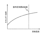
- FIG. 13 is a diagram showing the relationship between the evaporation temperature and energy efficiency. From FIG. 13, it can be seen that in order to operate the refrigeration cycle with high energy efficiency, the evaporation temperature should be increased. And even if the evaporation temperature exceeds the indoor air dew point temperature, it is possible to operate with high energy efficiency.
- FIG. 14 is a diagram for explaining the relationship between the evaporation temperature and the amount of dehumidification in each case where dehumidification is performed by the humidity control apparatus and dehumidification is performed by the indoor unit.
- the horizontal axis represents the evaporation temperature
- the vertical axis represents the dehumidification amount.
- both the indoor unit 10b and the humidity control device 30 decrease the dehumidification amount as the evaporation temperature increases.
- the indoor unit 10b decreases the dehumidification amount.
- the humidity controller 30 does not immediately become 0 even when the evaporation temperature exceeds the dew point temperature, and can secure the necessary dehumidification amount.
- the humidity control apparatus 30 since the required dehumidification amount can be ensured even if the evaporation temperature is higher than the indoor air dew point temperature, the humidity control apparatus 30 is better than ensuring the necessary dehumidification amount in the indoor unit 10b. It can be seen that dehumidification is more efficient.
- the air conditioning system 100 configured as described above provides the same effects as those of the first embodiment, and dehumidification is performed by the humidity control apparatus 30, so that it is not necessary to perform dehumidification by the indoor unit 10 b for sensible heat treatment.
- it is possible to perform an operation for increasing the evaporation temperature as compared with the case where dehumidification is performed in the indoor unit 10b. Therefore, the efficiency of the entire system can be increased, and power consumption can be reduced.
- a humidity control device that can dehumidify using a refrigerant having a high evaporation temperature
- temperature control and humidity control can be performed with high efficiency regardless of whether the load generation source is indoors or outdoors.
- the humidity control device 30 is connected to the outdoor unit 10a and disposed indoors, it is not necessary to mount the compressor 11 in the humidity control device 30, and the humidity control device 30 can be reduced in weight.
- the humidity control device 30 does not have a desorption heat source such as a heating device for desorbing moisture from the moisture adsorption / desorption devices 33a and 33b, it can be connected in the same manner as a conventional indoor unit, and the existing air conditioning It becomes possible to replace the indoor unit of the system with the humidity control device 30.
- a desorption heat source such as a heating device for desorbing moisture from the moisture adsorption / desorption devices 33a and 33b
- the air conditioning system of the third embodiment includes the outdoor unit 10a, the indoor unit 10b, the humidity control device 30 and the controller 40A, and the indoor unit 10b and the humidity control device 30.
- the air-conditioning of the same space is the same, and the following points are different. That is, in the second embodiment, the outdoor unit 10a, the indoor unit 10b, and the humidity control device 30 are connected by a single refrigerant circuit, whereas in the third embodiment, the indoor unit 10b and the humidity control device 30 are connected. The difference is that they constitute independent refrigerant circuits.
- the cooling device 32 is comprised by the evaporator of the refrigerant circuit by the side of the humidity control apparatus 30.
- FIG. In the following, the third embodiment will be described focusing on the differences from the second embodiment.
- FIG. 15 is a diagram showing a configuration of an air conditioning system according to Embodiment 3 of the present invention.
- an air conditioner 10 is configured by connecting an indoor unit 10b to an outdoor unit 10a.
- the humidity control apparatus 30 is connected to the outdoor unit 30a.
- the outdoor unit 10 a and the indoor unit 10 b are connected to the liquid side main pipe 102 and the gas side main pipe 103 by transmission lines 101.
- the outdoor unit 30a and the humidity control apparatus 30 are connected to the liquid side main pipe 102 and the gas side main pipe 103, which are different from the air conditioner 10 side, by transmission lines 101.
- the controller 40A is connected to each of the outdoor unit 10a and the outdoor unit 30a by the transmission line 101.
- each of the humidity control apparatus 30 and the air conditioner 10 Although illustration of the refrigerant circuit of each of the humidity control apparatus 30 and the air conditioner 10 is omitted, the compressor, the four-way valve (only the air conditioner 10 side), the heat source side heat exchanger, the expansion valve, and the use side heat exchanger are all shown. Are sequentially connected by piping.
- the compressor provided in each of the outdoor unit 10a and the outdoor unit 30a is a compressor having a smaller compressor capacity than the compressor provided in the outdoor unit 10a according to the second embodiment, which is configured entirely with one refrigerant circuit. It can be. For this reason, the input power when lowering the evaporation temperature by the same temperature can be lower than that of the outdoor unit 10a side of the second embodiment.
- the same effects as those of Embodiments 1 and 2 can be obtained, and the refrigerant circuits of the humidity control device 30 and the indoor unit 10b are independent.
- the evaporation temperature of the refrigerant circuit on the humidity control device 30 side and the evaporation temperature of the refrigerant circuit on the indoor unit 10b side can be set separately. Therefore, in the refrigerant circuit on the side of the indoor unit 10b for sensible heat treatment, the evaporating temperature can be set only for temperature control. Therefore, the humidity controller 30 and the indoor unit 10b are configured by the same refrigerant circuit. Compared with the configuration of the second embodiment, the evaporation temperature can be further increased, and the efficiency of the entire air conditioning system can be improved.
- the evaporation temperature of the refrigerant circuit on the humidity control device 30 side is lowered to increase the dehumidification amount, and on the indoor unit 10b side, the evaporation temperature of the refrigerant circuit is raised to increase efficiency.
- the sensible heat treatment it is possible to process the air conditioning load with high efficiency while maintaining comfort. Therefore, in the air conditioning system 100A, it is possible to cope with highly efficient operation regardless of the load state.
- Embodiment 4 In the air conditioning system of the fourth embodiment, an outside air processing device is further connected to the air conditioning system 100 of the second embodiment shown in FIG. 10, and the humidity control device 30, the indoor unit 10b, and the outside air processing device have the same space. This is an air conditioning system. In the following, the fourth embodiment will be described focusing on the differences from the second embodiment.
- FIG. 16 is a diagram showing a configuration of an air conditioning system according to Embodiment 4 of the present invention.
- the air conditioning system 100B is configured to include an outside air treatment device 50 for treating outside air in addition to the indoor unit 10b for sensible heat treatment and the humidity control device 30 for latent heat treatment.
- the outside air processing device 50 is a device for adjusting the temperature and humidity of outside air taken in from the outside and supplying it to the inside of the room, and an expansion valve (not shown) capable of pulse-controlling the valve opening using a stepping motor; , Indoor heat exchanger 52, total heat exchanger 53, humidifier 54, air supply blower (not shown), exhaust blower (not shown), and external processing control board (not shown). )).
- the total heat exchanger 53 is a heat exchanger that performs total heat exchange between the outside air OA and the indoor return air RA.
- the refrigerant circuit of the outdoor air processing device 50 is the same as that of the indoor unit 10b, and an expansion valve (not shown) and the indoor heat exchanger 52 of the outdoor air processing device 50 are provided with a liquid side main pipe 102 and a gas side main pipe 103 extending from the outdoor unit 10a. Is connected to the outdoor unit 10a in parallel. Further, the outside air processing device 50 and the outdoor unit 10a are connected by a transmission line 101. In FIG. 16, the number of connected outside air processing apparatuses 50 is one, but is not limited to one, and may be two or more.
- the outside air OA passes through the total heat exchanger 53, the indoor heat exchanger 52, and the humidifying device 54 in this order, and is supplied indoors as the supply air SA.
- the indoor return air RA passes through the total heat exchanger 53 and is discharged to the outside as exhaust EA. Since the total heat exchanger 53 performs total heat exchange between the outside air OA and the indoor return air RA, the load generated in the room can be reduced as compared with the case where the outside air is directly supplied to the room for ventilation. It is possible to reduce the input of the compressor 11 (see FIG. 11) of the outdoor unit 10a.
- the same effects as those of the first and second embodiments can be obtained, and the outside air processing device 50 is provided. Therefore, the outside air is directly removed without providing the outside air processing device 50. Compared with the case of introducing indoors, the input of the compressor 11 of the outdoor unit 10a can be reduced.
- the outdoor unit 10a when the outside air is hotter and humid than the room air (the outdoor unit 10a is in cooling operation), the outside air after passing through the total heat exchanger 53 is hotter and humider than the room air. Therefore, the difference between the evaporation temperature of the refrigerant flowing through the indoor heat exchanger 52 and the passing air temperature in the outdoor air processing device 50 is increased as compared with the difference between the evaporation temperature of the indoor heat exchanger 22 of the indoor unit 10b and the indoor air.
- the indoor heat exchanger 52 can be heat-treated with higher efficiency than the indoor heat exchanger 22.
- the outdoor unit 10a when the outside air has a lower temperature and lower humidity than the room air (the outdoor unit 10a is in a heating operation), the outside air after passing through the total heat exchanger 53 has a lower temperature and humidity than the room air. Therefore, the difference between the condensing temperature of the refrigerant flowing through the indoor heat exchanger 52 and the passing air temperature in the outdoor air processing device 50 is increased compared to the difference between the evaporation temperature of the indoor heat exchanger 22 of the indoor unit 10b and the indoor air.
- the indoor heat exchanger 52 can be heat-treated with higher efficiency than the indoor heat exchanger 22.
- the humidifier 54 When heating and humidifying operation is performed in winter, it is possible to humidify the room by using the humidifier 54.
- the humidifier 54 a water supply type moisture permeable membrane, an ultrasonic humidifier or the like can be used.
- outside air processing device 50 Since the outside air processing device 50 is not equipped with a compressor, it is not necessary to mount a compressor on all the devices (indoor unit 10b, humidity control device 30, and outside air processing device 50) arranged behind the ceiling, and the weight is reduced. In addition, downsizing is possible. Therefore, the work burden at the time of installing the air conditioning system 100B can be reduced.
- a sensor for detecting the temperature and humidity of the outside air is provided in the outside air processing device 50 so that the outside air information is obtained from the outside air processing device 50.
- the outside air processing device 50 If load processing is performed and the humidity control apparatus 30 and the indoor unit 10b are stopped, it becomes possible to save energy.
- Embodiment 5 The air conditioning system 100C of the fifth embodiment is the same as the fourth embodiment in that the air conditioning of the same space is performed by the humidity control device 30, the indoor unit 10b, and the outside air processing device 50, and the following points are provided. Different.
- the air conditioning system 100C is configured by making the humidity control device 30 independent in the air conditioning system 100B of the fourth embodiment shown in FIG. 16 and by a refrigerant circuit separate from the indoor unit 10b and the outside air processing device 50 side. .
- the following description will focus on the differences of the fifth embodiment from the fourth embodiment.
- FIG. 17 is a diagram showing a configuration of an air-conditioning system according to Embodiment 5 of the present invention.
- an indoor unit 10 b is connected to an outdoor unit 10 a to constitute an air conditioner 10, and an outside air processing device 50 is further connected to the air conditioner 10.
- the humidity control apparatus 30 is connected to the outdoor unit 30a, and the independent refrigerant circuit different from the air conditioner 10 is comprised.
- the outdoor unit 10 a and the indoor unit 10 b are connected to the liquid side main pipe 102 and the gas side main pipe 103 by transmission lines 101.
- the compressor provided in each of the outdoor unit 10a and the outdoor unit 30a is a compressor having a smaller compressor capacity than the compressor provided in the outdoor unit 10a according to the second embodiment, which is configured entirely with one refrigerant circuit.
- the input power when lowering the evaporation temperature by the same temperature can be made lower than that on the outdoor unit 10a side of the second embodiment.
- the outside air processing device 50 is the same as the outside air processing device 50 according to the fourth embodiment, the description of the configuration and operation description is omitted.
- the same operational effects as those of the first to fourth embodiments can be obtained, and further the following effects can be obtained. That is, since the refrigerant circuit to which the indoor unit 10b and the outside air processing device 50 are connected and the refrigerant circuit on the humidity control device 30 side for latent heat treatment are separated, it is not necessary to perform dehumidification on the air conditioner 10 side. Therefore, only the temperature adjustment needs to be performed on the air conditioner 10 side, an operation for further increasing the evaporation temperature is possible, and power consumption can be reduced.
- 1 Body 1a Discharge pressure sensor, 1b Suction pressure sensor, 2 Air passage, 2a Liquid tube temperature sensor, 2b Gas tube temperature sensor, 2c Outside air temperature sensor, 2d Air temperature sensor, 3 Suction port, 3a Temperature and humidity sensor, 4 Suction Exit, 10 air conditioner, 10a outdoor unit, 10b indoor unit, 11 compressor, 12 outdoor heat exchanger, 13 four-way valve, 14 accumulator, 15 outdoor blower, 16 outdoor unit control board, 20 humidity control device, 21 expansion valve , 22 Indoor heat exchanger, 23 Indoor air blower, 24 Indoor unit control board, 30 Humidity control device, 30a Outdoor unit, 31 Expansion valve, 32 Cooling device, 33a, 33b Moisture adsorption / desorption device, 34a, 34b switching device, 35 Indoor blower, 36 humidity control board, 40 controller, 40A controller, 50 outside Treatment equipment, 52 indoor heat exchanger, 53 total heat exchanger, 54 humidifier, 100 air conditioning system, 100A air conditioning system, 100B air conditioning system, 100C air conditioning system, 101 transmission line
Landscapes
- Engineering & Computer Science (AREA)
- Chemical & Material Sciences (AREA)
- Combustion & Propulsion (AREA)
- Mechanical Engineering (AREA)
- General Engineering & Computer Science (AREA)
- Thermal Sciences (AREA)
- Physics & Mathematics (AREA)
- Analytical Chemistry (AREA)
- General Chemical & Material Sciences (AREA)
- Oil, Petroleum & Natural Gas (AREA)
- Chemical Kinetics & Catalysis (AREA)
- Central Air Conditioning (AREA)
- Air Conditioning Control Device (AREA)
- Drying Of Gases (AREA)
Abstract
Priority Applications (5)
| Application Number | Priority Date | Filing Date | Title |
|---|---|---|---|
| US14/234,765 US9297546B2 (en) | 2011-07-27 | 2011-07-27 | Humidity control apparatus and air-conditioning system |
| CN201180072577.8A CN103717976B (zh) | 2011-07-27 | 2011-07-27 | 调湿装置以及空气调节系统 |
| PCT/JP2011/004238 WO2013014708A1 (fr) | 2011-07-27 | 2011-07-27 | Dispositif de régulation d'humidité et système de climatisation |
| JP2013525436A JP5822931B2 (ja) | 2011-07-27 | 2011-07-27 | 調湿装置、空気調和システム及び調湿装置の制御方法 |
| EP11870018.6A EP2741019B1 (fr) | 2011-07-27 | 2011-07-27 | Dispositif de régulation d'humidité et système de climatisation |
Applications Claiming Priority (1)
| Application Number | Priority Date | Filing Date | Title |
|---|---|---|---|
| PCT/JP2011/004238 WO2013014708A1 (fr) | 2011-07-27 | 2011-07-27 | Dispositif de régulation d'humidité et système de climatisation |
Publications (1)
| Publication Number | Publication Date |
|---|---|
| WO2013014708A1 true WO2013014708A1 (fr) | 2013-01-31 |
Family
ID=47600601
Family Applications (1)
| Application Number | Title | Priority Date | Filing Date |
|---|---|---|---|
| PCT/JP2011/004238 Ceased WO2013014708A1 (fr) | 2011-07-27 | 2011-07-27 | Dispositif de régulation d'humidité et système de climatisation |
Country Status (5)
| Country | Link |
|---|---|
| US (1) | US9297546B2 (fr) |
| EP (1) | EP2741019B1 (fr) |
| JP (1) | JP5822931B2 (fr) |
| CN (1) | CN103717976B (fr) |
| WO (1) | WO2013014708A1 (fr) |
Cited By (4)
| Publication number | Priority date | Publication date | Assignee | Title |
|---|---|---|---|---|
| JP2015218945A (ja) * | 2014-05-16 | 2015-12-07 | サンポット株式会社 | ヒートポンプシステム |
| US20170097165A1 (en) * | 2014-07-04 | 2017-04-06 | Mitsubishi Electric Corporation | Ventilation device |
| JP2020012603A (ja) * | 2018-07-19 | 2020-01-23 | 三菱電機株式会社 | 空気調和システム |
| WO2025033088A1 (fr) * | 2023-08-08 | 2025-02-13 | シャープ株式会社 | Dispositif d'absorption d'humidité et dispositif de lavage/séchage de vaisselle |
Families Citing this family (19)
| Publication number | Priority date | Publication date | Assignee | Title |
|---|---|---|---|---|
| ES2109369T3 (es) | 1992-03-16 | 1998-01-16 | Zip Charge Co Ltd | Cargador rapido y metodo de carga rapida para pilas de niquel-cadmio. |
| WO2012073386A1 (fr) * | 2010-12-02 | 2012-06-07 | 三菱電機株式会社 | Dispositif déshumidificateur |
| JP5310881B2 (ja) * | 2012-01-12 | 2013-10-09 | ダイキン工業株式会社 | 空調制御装置 |
| US10046371B2 (en) * | 2013-03-29 | 2018-08-14 | Semes Co., Ltd. | Recycling unit, substrate treating apparatus and recycling method using the recycling unit |
| WO2014184883A1 (fr) * | 2013-05-14 | 2014-11-20 | 三菱電機株式会社 | Système de climatisation |
| TW201542986A (zh) * | 2014-05-06 | 2015-11-16 | Altrason Inc | 濕度調整裝置 |
| JP6257788B2 (ja) * | 2014-09-26 | 2018-01-10 | 三菱電機株式会社 | 除湿装置 |
| TWI637129B (zh) | 2015-07-07 | 2018-10-01 | 創昇科技股份有限公司 | 濕度調控系統 |
| CN106016858B (zh) * | 2016-05-12 | 2019-06-21 | 上海交通大学 | 空气调节装置 |
| JP6881578B2 (ja) * | 2017-06-14 | 2021-06-02 | ダイキン工業株式会社 | 調湿ユニット |
| CN109323421B (zh) * | 2018-09-30 | 2021-04-20 | 广东美的制冷设备有限公司 | 空调器及其控制方法、装置 |
| JP6974771B2 (ja) * | 2020-03-16 | 2021-12-01 | ダイキン工業株式会社 | 加湿ユニット |
| CN113623934B (zh) * | 2020-05-08 | 2022-10-28 | 青岛海尔电冰箱有限公司 | 风冷冰箱的控制方法与风冷冰箱 |
| CN111706930B (zh) * | 2020-07-02 | 2021-06-11 | 北京工业大学 | 模块化家用空气处理器 |
| CN112413857B (zh) * | 2020-11-23 | 2022-05-17 | 珠海格力电器股份有限公司 | 空调器控制方法、装置、空调器及存储介质 |
| CN113028602B (zh) * | 2021-03-23 | 2022-06-07 | 江苏碳元舒适加建筑科技有限公司 | 双冷源新风除湿机的运行控制方法及控制系统 |
| CN113531760B (zh) * | 2021-06-03 | 2022-08-02 | 珠海格力电器股份有限公司 | 湿度控制方法、装置、存储介质及处理器 |
| CN116202201B (zh) * | 2021-11-30 | 2025-11-18 | 青岛海尔空调器有限总公司 | 潜热型空调的控制方法、装置和潜热型空调 |
| DE102024109485A1 (de) * | 2024-04-04 | 2025-10-09 | Hengst Se | Fluidreinigungsvorrichtung, brennstoffzellensystem und verfahren zum reinigen eines fluidstroms |
Citations (12)
| Publication number | Priority date | Publication date | Assignee | Title |
|---|---|---|---|---|
| JPS4820993B1 (fr) * | 1964-05-28 | 1973-06-25 | ||
| JPH0339831A (ja) * | 1989-07-04 | 1991-02-20 | Matsushita Seiko Co Ltd | 換気空調装置 |
| JP2001173992A (ja) * | 1999-12-14 | 2001-06-29 | Denso Corp | 空調方法および空調装置 |
| JP2002191971A (ja) * | 2000-12-27 | 2002-07-10 | Daikin Ind Ltd | 吸着素子構造体及び調湿装置 |
| JP3540530B2 (ja) | 1996-12-13 | 2004-07-07 | 東芝キヤリア株式会社 | 空気調和装置 |
| JP2005034838A (ja) * | 2003-07-03 | 2005-02-10 | Matsushita Electric Ind Co Ltd | 除湿装置 |
| JP2005049059A (ja) * | 2003-07-31 | 2005-02-24 | Daikin Ind Ltd | 空気調和システム |
| JP2005131544A (ja) * | 2003-10-30 | 2005-05-26 | Kobe Steel Ltd | 圧縮機のドライヤ設備及び四方切替え弁 |
| JP2005291587A (ja) * | 2004-03-31 | 2005-10-20 | Daikin Ind Ltd | 空気調和システム |
| JP2010084970A (ja) * | 2008-09-30 | 2010-04-15 | Daikin Ind Ltd | 空調システムおよび熱交換ユニット |
| JP2010121912A (ja) | 2008-11-21 | 2010-06-03 | Daikin Ind Ltd | 空調システム |
| JP2010249485A (ja) * | 2009-03-24 | 2010-11-04 | Mitsubishi Electric Corp | 空気調和装置及び空気調和システム |
Family Cites Families (12)
| Publication number | Priority date | Publication date | Assignee | Title |
|---|---|---|---|---|
| US4719761A (en) | 1986-05-30 | 1988-01-19 | Cromer Charles J | Cooling system |
| US5758508A (en) * | 1996-02-05 | 1998-06-02 | Larouche Industries Inc. | Method and apparatus for cooling warm moisture-laden air |
| JP2000061251A (ja) * | 1998-08-20 | 2000-02-29 | Ebara Corp | 除湿装置 |
| JP2003161465A (ja) * | 2001-11-26 | 2003-06-06 | Daikin Ind Ltd | 調湿装置 |
| JP3695417B2 (ja) * | 2002-02-04 | 2005-09-14 | ダイキン工業株式会社 | 調湿装置 |
| JP3646722B2 (ja) * | 2003-08-18 | 2005-05-11 | ダイキン工業株式会社 | 調湿装置 |
| JP3712001B2 (ja) * | 2004-03-31 | 2005-11-02 | ダイキン工業株式会社 | 空気調和機および空気調和機の制御方法 |
| JP3711999B2 (ja) * | 2004-03-31 | 2005-11-02 | ダイキン工業株式会社 | 調湿装置 |
| JP4513380B2 (ja) | 2004-03-31 | 2010-07-28 | ダイキン工業株式会社 | 空気調和システム |
| CN101699177B (zh) * | 2009-01-08 | 2012-05-02 | 上海交通大学 | 再生式除湿换热器 |
| JP2011085270A (ja) * | 2009-10-13 | 2011-04-28 | Yamatake Corp | デシカント空調システムおよびその運転方法 |
| WO2012073386A1 (fr) | 2010-12-02 | 2012-06-07 | 三菱電機株式会社 | Dispositif déshumidificateur |
-
2011
- 2011-07-27 JP JP2013525436A patent/JP5822931B2/ja active Active
- 2011-07-27 CN CN201180072577.8A patent/CN103717976B/zh not_active Expired - Fee Related
- 2011-07-27 WO PCT/JP2011/004238 patent/WO2013014708A1/fr not_active Ceased
- 2011-07-27 US US14/234,765 patent/US9297546B2/en active Active
- 2011-07-27 EP EP11870018.6A patent/EP2741019B1/fr active Active
Patent Citations (12)
| Publication number | Priority date | Publication date | Assignee | Title |
|---|---|---|---|---|
| JPS4820993B1 (fr) * | 1964-05-28 | 1973-06-25 | ||
| JPH0339831A (ja) * | 1989-07-04 | 1991-02-20 | Matsushita Seiko Co Ltd | 換気空調装置 |
| JP3540530B2 (ja) | 1996-12-13 | 2004-07-07 | 東芝キヤリア株式会社 | 空気調和装置 |
| JP2001173992A (ja) * | 1999-12-14 | 2001-06-29 | Denso Corp | 空調方法および空調装置 |
| JP2002191971A (ja) * | 2000-12-27 | 2002-07-10 | Daikin Ind Ltd | 吸着素子構造体及び調湿装置 |
| JP2005034838A (ja) * | 2003-07-03 | 2005-02-10 | Matsushita Electric Ind Co Ltd | 除湿装置 |
| JP2005049059A (ja) * | 2003-07-31 | 2005-02-24 | Daikin Ind Ltd | 空気調和システム |
| JP2005131544A (ja) * | 2003-10-30 | 2005-05-26 | Kobe Steel Ltd | 圧縮機のドライヤ設備及び四方切替え弁 |
| JP2005291587A (ja) * | 2004-03-31 | 2005-10-20 | Daikin Ind Ltd | 空気調和システム |
| JP2010084970A (ja) * | 2008-09-30 | 2010-04-15 | Daikin Ind Ltd | 空調システムおよび熱交換ユニット |
| JP2010121912A (ja) | 2008-11-21 | 2010-06-03 | Daikin Ind Ltd | 空調システム |
| JP2010249485A (ja) * | 2009-03-24 | 2010-11-04 | Mitsubishi Electric Corp | 空気調和装置及び空気調和システム |
Non-Patent Citations (1)
| Title |
|---|
| See also references of EP2741019A4 |
Cited By (4)
| Publication number | Priority date | Publication date | Assignee | Title |
|---|---|---|---|---|
| JP2015218945A (ja) * | 2014-05-16 | 2015-12-07 | サンポット株式会社 | ヒートポンプシステム |
| US20170097165A1 (en) * | 2014-07-04 | 2017-04-06 | Mitsubishi Electric Corporation | Ventilation device |
| JP2020012603A (ja) * | 2018-07-19 | 2020-01-23 | 三菱電機株式会社 | 空気調和システム |
| WO2025033088A1 (fr) * | 2023-08-08 | 2025-02-13 | シャープ株式会社 | Dispositif d'absorption d'humidité et dispositif de lavage/séchage de vaisselle |
Also Published As
| Publication number | Publication date |
|---|---|
| EP2741019B1 (fr) | 2019-09-04 |
| CN103717976B (zh) | 2017-04-12 |
| CN103717976A (zh) | 2014-04-09 |
| JPWO2013014708A1 (ja) | 2015-02-23 |
| US9297546B2 (en) | 2016-03-29 |
| JP5822931B2 (ja) | 2015-11-25 |
| EP2741019A4 (fr) | 2015-07-22 |
| EP2741019A1 (fr) | 2014-06-11 |
| US20140157806A1 (en) | 2014-06-12 |
Similar Documents
| Publication | Publication Date | Title |
|---|---|---|
| JP5822931B2 (ja) | 調湿装置、空気調和システム及び調湿装置の制御方法 | |
| JP5068235B2 (ja) | 冷凍空調装置 | |
| JP6494765B2 (ja) | 空気調和システム | |
| JP4835688B2 (ja) | 空気調和装置、空調システム | |
| EP2647416B1 (fr) | Dispositif déshumidificateur | |
| JP5631415B2 (ja) | 空気調和システム及び調湿装置 | |
| JP5868416B2 (ja) | 冷凍空調装置及び調湿装置 | |
| WO2014167660A1 (fr) | Dispositif de déshumidification | |
| JP7113659B2 (ja) | 空気調和装置 | |
| JP5542777B2 (ja) | 空気調和装置 | |
| JP5062216B2 (ja) | 空調装置 | |
| JP2020012603A (ja) | 空気調和システム | |
| JP7126611B2 (ja) | 空気調和装置 | |
| JP2010127522A (ja) | 空調システム | |
| WO2015125251A1 (fr) | Dispositif de climatisation et procédé de commande de dispositif de climatisation | |
| JP7233538B2 (ja) | 空気調和装置 |
Legal Events
| Date | Code | Title | Description |
|---|---|---|---|
| 121 | Ep: the epo has been informed by wipo that ep was designated in this application |
Ref document number: 11870018 Country of ref document: EP Kind code of ref document: A1 |
|
| ENP | Entry into the national phase |
Ref document number: 2013525436 Country of ref document: JP Kind code of ref document: A |
|
| WWE | Wipo information: entry into national phase |
Ref document number: 14234765 Country of ref document: US |
|
| NENP | Non-entry into the national phase |
Ref country code: DE |
|
| WWE | Wipo information: entry into national phase |
Ref document number: 2011870018 Country of ref document: EP |