WO2013014751A1 - 刈り払い機及び角度調整用アタッチメント - Google Patents
刈り払い機及び角度調整用アタッチメント Download PDFInfo
- Publication number
- WO2013014751A1 WO2013014751A1 PCT/JP2011/066947 JP2011066947W WO2013014751A1 WO 2013014751 A1 WO2013014751 A1 WO 2013014751A1 JP 2011066947 W JP2011066947 W JP 2011066947W WO 2013014751 A1 WO2013014751 A1 WO 2013014751A1
- Authority
- WO
- WIPO (PCT)
- Prior art keywords
- rotating
- rod
- wire
- rotary blade
- cylindrical portion
- Prior art date
- Legal status (The legal status is an assumption and is not a legal conclusion. Google has not performed a legal analysis and makes no representation as to the accuracy of the status listed.)
- Ceased
Links
Images


Classifications
-
- A—HUMAN NECESSITIES
- A01—AGRICULTURE; FORESTRY; ANIMAL HUSBANDRY; HUNTING; TRAPPING; FISHING
- A01D—HARVESTING; MOWING
- A01D34/00—Mowers; Mowing apparatus of harvesters
- A01D34/835—Mowers; Mowing apparatus of harvesters specially adapted for particular purposes
- A01D34/90—Mowers; Mowing apparatus of harvesters specially adapted for particular purposes for carrying by the operator
- A01D34/902—Ergonomic provisions
Definitions
- the present invention relates to an attachment for angle adjustment that can be attached to a brush cutter so that the angle of the brush cutter and the rotary blade can be adjusted.
- a mower is used to cut weeds in mountains, fields and paddy fields.
- a rotating circular rotary blade is provided at the tip of a rod having a predetermined length, and an engine for rotating the rotary blade is provided at the rear end of the rod.
- the rod is provided with a grip arm for the operator to grip, and the operator operates the brush cutter by gripping the grip arm with both hands.
- the rotational driving force from the engine is transmitted to the rotary blade by the flexible shaft, and the sliding lever is operated by operating the rotating lever at hand.
- the angle of the rotary blade can be adjusted by retracting the pipe against the urging force of the compression coil spring.
- JP 54-146724 A Japanese Utility Model Publication No. 3-17619
- the present invention has been made to solve the above-mentioned problems, and the object of the present invention is to make it possible to adjust the angle from a brush cutter that can reduce the component cost and reduce the weight, and an existing cutter that cannot adjust the angle. It is in providing the attachment for angle adjustment which can be comprised in.
- the rod is configured such that the prime mover and the inside are formed hollow, and the shaft for transmitting the rotational driving force of the prime mover attached to the rear end portion is inserted into the hollow space inside.
- the angle adjusting portion includes a mounting portion for mounting on the rod tip portion on the side where the prime mover is provided and a hollow cylinder extending in a direction perpendicular to the axial direction of the rod
- a first rotating part having a portion and an inner wall or an outer wall surface of the cylindrical part of the first rotating part.
- a flexible connecting member that connects the shaft in the rod on the rotating side and the shaft in the rod on the rotary blade support portion, and the top end of the cylindrical portion of the first rotating portion or the second rotating portion.
- the rotational driving force is transmitted to the rotary blade by the flexible connecting member, the rotational driving force is reliably transmitted even when the angle of the rotary blade support portion is changed. And since it is not necessary to use a gear etc., reduction of parts cost and weight reduction can be achieved.
- the cylindrical part located on the outer peripheral side of the first rotating part or the second rotating part is provided with caps that close the inside of the cylindrical part and are detachable. It is good. According to this configuration, it is possible to prevent dust such as grass from entering the first rotating part and the second rotating part by attaching a cap, and there is something in the angle adjusting part. If a problem occurs, you can remove the cap and check the inside.
- the angle adjustment attachment is attached to the middle part of the rod of the brush cutter, the attachment part for attaching to the rod tip on the side where the prime mover is provided, and A first rotating part extending in a direction orthogonal to the axial direction of the rod and having a hollow cylindrical part inside, and a cylindrical part of the first rotating part arranged inside or outside the cylindrical part of the first rotating part
- the inner part or the outer wall surface of the cylindrical part is slidable with the axial direction of the cylindrical part as the axis
- the second part has a hollow cylindrical part and an attachment part for attaching to the rod rear end part on the rotary blade support part side.
- a flexible connecting member to be connected, and the tip is first.
- the second wire connected to the upper surface, the rear end portion of the first wire and the rear end portion of the second wire are connected, and the pushing and pulling operations of the first wire and the second wire are opposite to each other. And an operating lever.
- the rod of the existing brush cutter that cannot adjust the angle and the shaft in the rod are cut in the vicinity of the tip, and the mounting portion of the first rotating portion is attached to the tip of the rod on the prime mover side.
- An angle adjustable mower can be obtained.
- the cylindrical part located on the outer peripheral side of the first rotating part or the second rotating part is provided with caps that close the inside of the cylindrical part and are detachable. It is good. According to this configuration, it is possible to prevent dust such as grass from entering the first rotating part and the second rotating part by attaching a cap, and there is something in the angle adjusting part. If a problem occurs, you can remove the cap and check the inside.
- the angle-adjustable brush cutter can be provided at a low weight and at a low cost. Moreover, according to the attachment for angle adjustment concerning this invention, it can comprise so that an angle can be adjusted from the existing brush cutter which cannot adjust an angle.
- FIG. 1 It is a perspective view which shows the whole structure of the brush cutter which concerns on this invention. It is a perspective view which shows the external appearance of an angle adjustment part. It is a perspective view which shows the place which has removed the 2nd rotation part in the angle adjustment part of FIG. It is sectional drawing which shows the assembly
- FIG. 1 shows the overall configuration of the brush cutter.
- the mower 30 has a prime mover 32 attached to the rear end of the long rod 31.
- the rotational driving force of the prime mover 32 is transmitted to the rotary blade 34 provided at the tip of the rod 31, and the rotary blade 34 rotates to cut grass such as weeds.
- a handle 37 that can be gripped by the operator is attached to a slightly rear end portion from the middle portion of the rod 31.
- the handle 37 shown here is substantially U-shaped, but the shape of the handle 37 is not limited to such a shape.
- the rod 31 has a hollow interior, and a shaft 38 for transmitting the rotational force of the prime mover 32 (rotation axis in the claims: see FIGS. 2 and 3) passes through the hollow portion of the rod 31.
- the shaft 38 is a metal rod-like member, and rotates about an axis. The rotational force of the shaft 38 is changed in direction of rotation by the rotary blade support portion 40 and transmitted to the rotary blade 34.
- an angle adjusting unit 41 for adjusting the angle of the rotary blade 34 is provided in the middle of the rod 31 in the middle of the rod 31.
- the angle adjustment unit 41 is rotatable about an axis that is oriented in a direction orthogonal to the axial direction of the rod 31 (horizontal direction in the present embodiment) so that the angle of the rod 31 can be changed in the middle of the rod 31. It is.
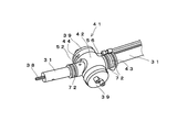
- FIG. 2 and 3 show the external configuration of the angle adjustment unit 41.
- FIG. FIG. 4 is a cross-sectional view of the angle adjustment unit. Note that FIG. 3 shows an angle adjusting unit during assembly, and shows a place where a second rotating unit 44 (described later) is not mounted.
- the angle adjustment unit 41 is attached to the tip of the rod 31 on the side where the prime mover 32 is attached, and a direction orthogonal to the axial direction of the rod 31 (rotation axis direction of the angle adjustment unit: In the present embodiment, it has a first rotating portion 42 that extends in the horizontal direction) and has a hollow cylindrical portion 46 inside.
- the first rotating unit 42 incorporates a second rotating unit 44 so as to be capable of rotating, and the second rotating unit 44 has an axis in the horizontal direction with respect to the first rotating unit 42. As a result, the angle of the rotary blade 34 can be adjusted.
- the second rotating part 44 is disposed in the cylindrical part 46 of the first rotating part 42, and the cylindrical part 50 is slidably in contact with the inner wall surface of the cylindrical part 46 of the first rotating part 42. have.
- the cylindrical portion 50 is hollow inside.
- the second rotating portion 44 is provided with an attachment portion 52 for attaching to the rear end portion of the rod 31 on the rotary blade support portion 40 side.
- an attachment portion 52 that protrudes outside the first rotating portion 42 from the second rotating portion 44 accommodated therein is used for rotating the second rotating portion 44.
- a relief hole 45 that can be moved together is formed.
- the escape hole 45 is formed as a hole extending in the vertical direction so that the mounting portion 52 can move in the rotation direction of the second rotation member 44 (vertical direction in the present embodiment).
- a through hole 47 for penetrating the shaft 38 disposed inside the rod 31 is formed at a location on the opposite side of the mounting portion 52 of the second rotating portion 44.
- a detachable cap 39 is provided at an end of the cylindrical portion 46 of the first rotating portion in the axial direction of the cylinder so that the inside of the cylinder can be exposed and closed.
- the cap 39 is preferably mounted so that grass or the like does not enter the rotating parts 42 and 44 while the brush cutter 30 is used.
- the angle adjustment unit 41 is assembled, the inside of the cylindrical portions 46 and 50 can be seen by removing the cap 39.
- FIG. 5 shows a view of the inside of each cylindrical portion 46, 50 with the cap 39 removed.
- the shaft 38 is connected by a flexible connecting member 54 in the angle adjusting unit 41.
- Examples of the connecting member 54 include a metal spring that is freely bent.
- the connection member 54 rotates instead of the shaft 38. Therefore, in the angle adjustment unit 41, even when the second rotation unit 44 rotates with respect to the first rotation unit 42, the connecting member 54 bends and transmits the rotational driving force of the prime mover 32 to the rotary blade 34. it can.
- FIG. 6 shows the angle adjustment unit viewed from the opposite side of FIG.
- the rotation of the second rotation unit 44 relative to the first rotation unit 42 can be performed by operating two wires.
- the first wire 56 is attached to the upper portion of the second rotating portion 44 disposed inside, and is attached to the lower portion of the second rotating portion 44.
- the second wire 58 is provided.
- the rear ends of the first wire 56 and the second wire 58 are connected to an operation lever 70 provided on the handle 37 as will be described later, and are arranged along the surface of the rod 31 toward the angle adjustment unit 41.
- the first wire 56 enters the inside of the first rotating part 42 from an insertion hole (not shown) formed from the lower part of the first rotating part 42.
- the second wire 58 enters the inside of the first rotating part 42 from an insertion hole (not shown) formed from the upper part of the first rotating part 42.
- a storage groove for storing the wires 56 and 58 that have entered from the outside of the first rotating portion 42 is formed on the outer surface of the cylindrical portion 50 of the second rotating portion 44.
- the second rotating unit 44 can rotate without disturbing the wires 56 and 58 inside the first rotating unit 42.
- An insertion hole (not shown) for allowing the first wire 56 to enter the inside of the second rotating portion 44 is formed at a predetermined position of the cylindrical portion 50 of the second rotating portion 44. The wire 56 enters the second rotating portion 44 after the outer surface of the second rotating portion 44 is accommodated in the approximately half-circumferential groove.
- an insertion hole (not shown) for allowing the second wire 58 to enter the second rotating portion 44 is formed at a predetermined position of the second rotating portion 44. Enters the second rotating portion 44 after the outer surface of the second rotating portion 44 is accommodated in the approximately half-circumferential groove.
- wire fixing portions 60 and 61 for fixing the wires 56 and 58 are provided inside the cylindrical portion 50 of the second rotating portion 44.
- the first wire fixing portion 61 for fixing the first wire 56 is provided so as to protrude inward from the upper portion inside the second rotating portion 44, and is configured by a bolt and a nut capable of fixing the first wire 56.
- the fixing means 62 is provided.
- the second wire fixing portion 60 for fixing the second wire 58 is provided so as to protrude inward from the lower portion inside the second rotating portion 44, and from a bolt and a nut capable of fixing the second wire 58. It has a fixing means 63 configured.
- FIG. 7 shows the operation lever.
- the operation lever 70 is disposed at the proximal portion of the handle 37, and the rear ends of both the first wire 56 and the second wire 58 are connected.
- either the first wire 56 or the second wire 58 is wound around the operation lever 70 and pulled toward the hand side, and either one is on the distal end side. It is pushed out (to the angle adjustment unit 41 side).
- the angle adjustment unit 41 side For example, if the first wire 56 is pulled and the second wire 58 is pushed out, the upper side of the second rotating portion 44 to which the distal end portion of the first wire 56 is fixed is shown in FIG. Pulled clockwise, the second rotating part 44 rotates clockwise. For this reason, in FIG. 6, the angle of the rod on the rotary blade support portion 40 side connected to the second rotating portion 44 is changed with respect to the rod on the prime mover 32 side.
- the operation direction of the operation lever 70 is the other direction opposite to the above, for example, if the first wire 56 is pushed out and the second wire 58 is pulled, the tip of the second wire 58 is fixed. The lower side of the second rotating portion 44 is pulled counterclockwise by the second wire 58, and the second rotating portion rotates clockwise. For this reason, in FIG. 6, the angle is changed so that the rod on the rotary blade support portion 40 side connected to the second rotating portion 44 is lowered with respect to the rod on the prime mover 32 side.
- a brush cutter capable of adjusting the angle of the rotary blade 34 can be provided by attaching each component of the above-described embodiment to a normal brush cutter in which the angle of the rotary blade 34 cannot be adjusted. That is, the rod 31 of a normal brush cutter is cut halfway, and the shaft 38 inside the rod 31 is also cut. Of the rod 31 that has been cut, the tip of the rod 31 on the prime mover 32 side is inserted into the mounting portion 43 of the first rotating portion 42. A tightening band 72 may be attached around the attachment portion 43 to prevent the attachment portion 43 from coming off.
- the cut shaft 38 is connected by a flexible connecting member 54 such as a spring.
- the attachment portion 52 of the second rotating member 44 is attached to the rear end portion of the rod 31 on the rotary blade support portion 40 side.
- a tightening band 72 may also be attached around the attachment portion 52 to prevent detachment.
- the first rotating member on the prime mover side is provided on the outer side
- the second rotating member on the rotary blade side is provided on the inner side
- the second rotating member is provided on the outer side.
- the 1st rotation member may be arrange
- the mounting position of the operation lever 70 is not limited to the handle 37.
Landscapes
- Life Sciences & Earth Sciences (AREA)
- Environmental Sciences (AREA)
- Harvester Elements (AREA)
Abstract
部品コストが安く、また軽量化を図ることができ、既存の角度調整できない刈り払い機から角度調整できるように容易に構成することができる刈り払い機及び角度調整用アタッチメントを提供する。 ロッド31に取り付ける取付部43及び円筒部46を有する第1回動部42と、第1回動部42の円筒部46内部又は外部に配置され、円筒部46の軸線方向を軸線として摺動可能な円筒部50及びロッド31に取り付ける取付部52を有する第2回動部44と、原動機32側のロッド31内のシャフト38と、回転刃支持部側のロッド31内のシャフト38とを連結する可撓性の連結部材54と、先端部が円筒部46の上面又は円筒部50の上面に連結される第1ワイヤ56と、先端部が円筒部46の下面又は円筒部50の上面に連結される第2ワイヤ58と、両ワイヤ56、58の後端部が連結され、両ワイヤ56、58の押し引き動作を逆方向とする操作レバー70とを具備する。
Description
本発明は、刈り払い機及び回転刃の角度調整ができるように刈り払い機に装着可能な角度調整用アタッチメントに関する。
山野、畑、水田の畦などにおいて雑草を刈り取るために刈り払い機が用いられる。刈り払い機は、所定の長さのロッドの先端部に、回転する円形の回転刃が設けられ、ロッドの後端部には回転刃を回転駆動させるエンジンが設けられている。
また、ロッドには、操作者が把持するための把持アームが設けられており、操作者は把持アームを両手で把持して刈り払い機を操作する。
また、ロッドには、操作者が把持するための把持アームが設けられており、操作者は把持アームを両手で把持して刈り払い機を操作する。
ところで、斜面で雑草を刈り取る際などでは、回転刃が斜面と平行になるように操作者が把持アームを操作して刈り取りを行わなくてはならない。しかしながら、この作業は非常に重労働であるため、回転刃の角度を手元で調整したいという要望が従来から強かった。
そこで、回転刃の角度を調整可能な刈り払い機が従来より種々提案されている(例えば、特許文献1、特許文献2参照)。
例えば、特許文献1に記載された従来の刈り払い機によれば、ロッドの先端部付近にギアケースを設け、回転刃を軸支するケース体がギアケースに対して回動可能に設けている。すなわち、この構成によればエンジンからの回転駆動力はギアケース内に収納された傘歯歯車によって回転刃に伝達される。
例えば、特許文献1に記載された従来の刈り払い機によれば、ロッドの先端部付近にギアケースを設け、回転刃を軸支するケース体がギアケースに対して回動可能に設けている。すなわち、この構成によればエンジンからの回転駆動力はギアケース内に収納された傘歯歯車によって回転刃に伝達される。
また、特許文献2に記載された従来の刈り払い機によれば、エンジンからの回転駆動力は可撓性の軸によって回転刃に伝達されており、手元の回動レバーを操作して摺動パイプを圧縮コイルバネの付勢力に抗して後退させると回転刃の角度が調整できる。
上記の特許文献1に示したような構成では、傘歯歯車を用いて回転駆動力を回転刃に伝達していたので、部品コストがかさみ、また重量も重くなってしまうという課題がある。
また、特許文献2に示したような構成では、従来の回転刃の角度調整ができない刈り払い機を改造してこのような構成とすることができない。つまり、今まで回転刃の角度調整ができない刈り払い機を使用していた場合に、これに角度調整用の部品を取り付けることで角度調整ができるような要望に応えることができないという課題がある。
また、特許文献2に示したような構成では、従来の回転刃の角度調整ができない刈り払い機を改造してこのような構成とすることができない。つまり、今まで回転刃の角度調整ができない刈り払い機を使用していた場合に、これに角度調整用の部品を取り付けることで角度調整ができるような要望に応えることができないという課題がある。
そこで本発明は上記課題を解決すべくなされ、その目的とするところは、部品コストが安く、また軽量化を図ることができる刈り払い機、及び既存の角度調整できない刈り払い機から角度調整できるように構成することができる角度調整用アタッチメントを提供することにある。
本発明にかかる刈り払い機によれば、原動機と、内部が中空に形成され、後端部に取り付けられた原動機の回転駆動力を伝達するシャフトが内部の中空空間に挿通されて構成されるロッドと、内部に回転刃を回転駆動させるための駆動軸が内蔵され、回転刃を回転可能に支持する回転刃支持部と、ロッドの中途部に設けられ、回転刃の角度を調整する角度調整部とを具備する刈り払い機において、前記角度調整部は、原動機が設けられている側のロッド先端部に取り付けるための取付部及びロッドの軸線方向に対して直交する方向に延び内部が中空の円筒部を有する第1回動部と、第1回動部の円筒部内部又は外部に配置され、第1回動部の円筒部の内壁面又は外壁面に対して、円筒部の軸線方向を軸線として摺動可能な内部が中空の円筒部及び回転刃支持部側のロッド後端部に取り付けるための取付部を有する第2回動部と、第1回動部及び第2回動部を貫通して配置されており、原動機が設けられている側のロッド内のシャフトと、回転刃支持部側のロッド内のシャフトとを連結する可撓性の連結部材と、先端部が第1回動部の円筒部の上面又は第2回動部の円筒部の上面に連結される第1ワイヤと、先端部が第1回動部の円筒部の下面又は第2回動部の円筒部の上面に連結される第2ワイヤと、第1ワイヤの後端部と第2ワイヤの後端部とが連結され、第1ワイヤと第2ワイヤの押し引き動作が互いに逆方向となるように動作する操作レバーとを具備することを特徴としている。
この構成を採用することによって、第1回動部に対して第2回動部がロッドに対して直交する方向を軸線として回動可能である。このため、第2回動部の先端側に設けられた回転刃支持部の角度が調整可能となる。また、回転刃への回転駆動力の伝達は、可撓性の連結部材によって行われるので、回転刃支持部の角度を変えた際にも回転駆動力の伝達は確実に行われる。そして、歯車等を用いずに済むので、部品コストの低減及び軽量化を図ることができる。
この構成を採用することによって、第1回動部に対して第2回動部がロッドに対して直交する方向を軸線として回動可能である。このため、第2回動部の先端側に設けられた回転刃支持部の角度が調整可能となる。また、回転刃への回転駆動力の伝達は、可撓性の連結部材によって行われるので、回転刃支持部の角度を変えた際にも回転駆動力の伝達は確実に行われる。そして、歯車等を用いずに済むので、部品コストの低減及び軽量化を図ることができる。
また、前記第1回動部又は前記第2回動部のうち、外周側に位置する円筒部の両端には、円筒部内部を閉塞し、且つ着脱可能なキャップが取り付けられていることを特徴としてもよい。
この構成によれば、通常はキャップを装着していることで第1回動部及び第2回動部内に草などのゴミが進入しないようにすることができ、またこの角度調整部分に何か不具合が生じた場合においてはキャップを外して内部の確認をすることができる。
この構成によれば、通常はキャップを装着していることで第1回動部及び第2回動部内に草などのゴミが進入しないようにすることができ、またこの角度調整部分に何か不具合が生じた場合においてはキャップを外して内部の確認をすることができる。
本発明にかかる角度調整用アタッチメントによれば、刈り払い機のロッドの中途部に装着される角度調整用アタッチメントであって、原動機が設けられている側のロッド先端部に取り付けるための取付部及びロッドの軸線方向に対して直交する方向に延び内部が中空の円筒部を有する第1回動部と、第1回動部の円筒部内部又は外部に配置され、第1回動部の円筒部の内壁面又は外壁面に対して、円筒部の軸線方向を軸線として摺動可能な内部が中空の円筒部及び回転刃支持部側のロッド後端部に取り付けるための取付部を有する第2回動部と、第1回動部及び第2回動部を貫通して配置されており、原動機が設けられている側のロッド内のシャフトと、回転刃支持部側のロッド内のシャフトとを連結する可撓性の連結部材と、先端部が第1回動部の円筒部の上面又は第2回動部の円筒部の上面に連結される第1ワイヤと、先端部が第1回動部の円筒部の下面又は第2回動部の円筒部の上面に連結される第2ワイヤと、第1ワイヤの後端部と第2ワイヤの後端部とが連結され、第1ワイヤと第2ワイヤの押し引き動作が互いに逆方向となるように動作する操作レバーとを具備することを特徴としている。
また、このような構成であれば、既存の角度調整できない刈り払い機のロッド及びロッド内のシャフトを先端部近傍で切断し、原動機側のロッドの先端部に第1回動部の取付部を装着し、回転刃側のロッドの後端部に第2回動部の取付部を装着し、ロッド内に配置されている既存のシャフトを可撓性の連結部材で接続するだけで、容易に角度調整可能な刈り払い機とすることができる。
また、このような構成であれば、既存の角度調整できない刈り払い機のロッド及びロッド内のシャフトを先端部近傍で切断し、原動機側のロッドの先端部に第1回動部の取付部を装着し、回転刃側のロッドの後端部に第2回動部の取付部を装着し、ロッド内に配置されている既存のシャフトを可撓性の連結部材で接続するだけで、容易に角度調整可能な刈り払い機とすることができる。
また、前記第1回動部又は前記第2回動部のうち、外周側に位置する円筒部の両端には、円筒部内部を閉塞し、且つ着脱可能なキャップが取り付けられていることを特徴としてもよい。
この構成によれば、通常はキャップを装着していることで第1回動部及び第2回動部内に草などのゴミが進入しないようにすることができ、またこの角度調整部分に何か不具合が生じた場合においてはキャップを外して内部の確認をすることができる。
この構成によれば、通常はキャップを装着していることで第1回動部及び第2回動部内に草などのゴミが進入しないようにすることができ、またこの角度調整部分に何か不具合が生じた場合においてはキャップを外して内部の確認をすることができる。
本発明にかかる刈り払い機によれば、角度調整可能な刈り払い機を、軽量且つ低コストで提供することができる。
また、本発明にかかる角度調整用アタッチメントによれば、既存の角度調整できない刈り払い機から角度調整できるように構成することができる。
また、本発明にかかる角度調整用アタッチメントによれば、既存の角度調整できない刈り払い機から角度調整できるように構成することができる。
本発明に係る刈り払い機の好適な実施の形態を以下に説明する。
図1には刈り払い機の全体構成を示す。
刈り払い機30は、長尺なロッド31の後端部に原動機32が取り付けられている。原動機32の回転駆動力は、ロッド31の先端部に設けられた回転刃34に伝達され、回転刃34が回転することにより雑草等の草を刈ることができる。
図1には刈り払い機の全体構成を示す。
刈り払い機30は、長尺なロッド31の後端部に原動機32が取り付けられている。原動機32の回転駆動力は、ロッド31の先端部に設けられた回転刃34に伝達され、回転刃34が回転することにより雑草等の草を刈ることができる。
ロッド31の中間部分よりもやや後端部よりには、操作者が把持できるハンドル37が取り付けられている。ここで示すハンドル37はほぼU字状に形成されたものを図示しているが、ハンドル37の形状としてはこのような形状に限定されるものではない。
またロッド31は内部が中空に形成されており、ロッド31の中空部分には原動機32の回転力を伝達するためのシャフト38(特許請求の範囲でいう回転軸:図2、3参照)が貫通して配置されている。シャフト38は、金属製の棒状の部材であって、軸線を中心として回転する。
シャフト38の回転力は、回転刃支持部40によってその回転方向が転換され、回転刃34に伝達される。
シャフト38の回転力は、回転刃支持部40によってその回転方向が転換され、回転刃34に伝達される。
ロッド31の中途部には、回転刃34の角度を調整するための角度調整部41が設けられている。角度調整部41は、ロッド31の中途部でロッド31の角度を変更できるようにロッド31の軸線方向に対して直交する方向(本実施形態では水平方向)を向く軸線を中心にして回動可能である。
以下、角度調整部41について詳細に説明する。図2及び図3は、角度調整部41の外観構成を示している。また、図4は角度調整部の断面図を示している。なお、図3においては、組み立て中の角度調整部を示しており、第2回動部44(後述する)が装着されていないところを図示している。
角度調整部41は、原動機32が取り付けられている側のロッド31の先端部に取り付けるための取付部43、及びロッド31の軸線方向に対して直交する方向(角度調整部の回動軸線方向:本実施形態では水平方向)に延び内部が中空の円筒部46を有する第1回動部42を有している。
第1の回動部42には、第2の回動部44が回動可能に組み込まれており、この第2の回動部44が第1の回動部42に対して水平方向を軸線として回動することによって回転刃34の角度調整が可能となる。
角度調整部41は、原動機32が取り付けられている側のロッド31の先端部に取り付けるための取付部43、及びロッド31の軸線方向に対して直交する方向(角度調整部の回動軸線方向:本実施形態では水平方向)に延び内部が中空の円筒部46を有する第1回動部42を有している。
第1の回動部42には、第2の回動部44が回動可能に組み込まれており、この第2の回動部44が第1の回動部42に対して水平方向を軸線として回動することによって回転刃34の角度調整が可能となる。
第2の回動部44は、第1回動部42の円筒部46内に配置され、第1回動部42の円筒部46の内壁面に、外壁面が摺動可能に接する円筒部50を有している。円筒部50は内部が中空である。また、第2の回動部44には、回転刃支持部40側のロッド31の後端部に取り付けるための取付部52とが設けられている。
第1回動部42には、内部に収納している第2回動部44から第1回動部42の外側に突出している取付部52が、第2の回動部44の回動に合わせて移動できるような逃げ穴45が形成されている。
逃げ穴45は、第2回動部材44の回動方向(本実施形態では上下方向)に取付部52が移動できるように、上下方向に延びる穴として形成されている。
逃げ穴45は、第2回動部材44の回動方向(本実施形態では上下方向)に取付部52が移動できるように、上下方向に延びる穴として形成されている。
また、第2回動部44の、取付部52とは反対側の箇所には、ロッド31内部に配置されているシャフト38を貫通させるための貫通穴47が形成されている。
第1回動部の円筒部46の円筒の軸線方向端部には、円筒内部を露出及び閉塞できるように、着脱可能なキャップ39が設けられる。
キャップ39は、刈り払い機30を使用している間は、各回動部42,44内に草等が入り込まないように装着していることが好ましい。一方で、角度調整部41の組み付け時などには、キャップ39を外すことにより、円筒部46、50の内部が見えるようにすることができる。
キャップ39は、刈り払い機30を使用している間は、各回動部42,44内に草等が入り込まないように装着していることが好ましい。一方で、角度調整部41の組み付け時などには、キャップ39を外すことにより、円筒部46、50の内部が見えるようにすることができる。
図5は、キャップ39を外した状態で各円筒部46,50の内部を見たところを示す。
シャフト38は、角度調整部41内で可撓性の連結部材54によって連結されている。連結部材54の例としては、自由に屈曲する金属製のスプリング等が挙げられる。このように、角度調整部41内では、シャフト38の代わりに連結部材54が回転する。このため、角度調整部41において、第1回動部42に対して第2回動部44が回動した場合でも、連結部材54が曲折して原動機32の回転駆動力を回転刃34に伝達できる。
シャフト38は、角度調整部41内で可撓性の連結部材54によって連結されている。連結部材54の例としては、自由に屈曲する金属製のスプリング等が挙げられる。このように、角度調整部41内では、シャフト38の代わりに連結部材54が回転する。このため、角度調整部41において、第1回動部42に対して第2回動部44が回動した場合でも、連結部材54が曲折して原動機32の回転駆動力を回転刃34に伝達できる。
また、図6に、図5の反対側から角度調整部をみたところを示している。
第1回動部42に対する第2回動部44の回動は、2本のワイヤを操作することにより行うことができる。
本実施形態では、2本のワイヤのうち、内側に配置されている第2回動部44の上部に取り付けられているのが第1ワイヤ56であり、第2回動部44の下部に取り付けられているのが第2ワイヤ58である。
第1回動部42に対する第2回動部44の回動は、2本のワイヤを操作することにより行うことができる。
本実施形態では、2本のワイヤのうち、内側に配置されている第2回動部44の上部に取り付けられているのが第1ワイヤ56であり、第2回動部44の下部に取り付けられているのが第2ワイヤ58である。
第1ワイヤ56及び第2ワイヤ58は、その後端部が、後述するようにハンドル37に設けられた操作レバー70に接続されており、角度調整部41に向けてロッド31の表面に沿って配置されている。
第1ワイヤ56は、第1回動部42の下部よりに形成された挿入孔(図示せず)から、第1回動部42の内部に進入している。同様に、第2ワイヤ58は、第1回動部42の上部よりに形成された挿入孔(図示せず)から、第1回動部42の内部に進入している。
第1ワイヤ56は、第1回動部42の下部よりに形成された挿入孔(図示せず)から、第1回動部42の内部に進入している。同様に、第2ワイヤ58は、第1回動部42の上部よりに形成された挿入孔(図示せず)から、第1回動部42の内部に進入している。
また、第2回動部44の円筒部50の外側表面には、第1回動部42の外側から進入してきた各ワイヤ56,58を収納する収納溝が形成されている。各ワイヤ56,58が収納溝に収納されることにより、第2回動部44は第1回動部42の内部で各ワイヤ56,58が邪魔にならずに回動することができる。
第2回動部44の円筒部50の所定位置には、第1ワイヤ56を第2回動部44の内部に進入させるための挿入孔(図示せず)が形成されており、第1のワイヤ56は、第2回動部44の外側表面を約半周溝内に収納されてから第2回動部44内に進入する。
また、第2回動部44の所定位置には、第2ワイヤ58を第2回動部44の内部に進入させるための挿入孔(図示せず)が形成されており、第2のワイヤ58は、第2回動部44の外側表面を約半周溝内に収納されてから第2回動部44内に進入する。
第2回動部44の円筒部50の所定位置には、第1ワイヤ56を第2回動部44の内部に進入させるための挿入孔(図示せず)が形成されており、第1のワイヤ56は、第2回動部44の外側表面を約半周溝内に収納されてから第2回動部44内に進入する。
また、第2回動部44の所定位置には、第2ワイヤ58を第2回動部44の内部に進入させるための挿入孔(図示せず)が形成されており、第2のワイヤ58は、第2回動部44の外側表面を約半周溝内に収納されてから第2回動部44内に進入する。
第2回動部44の円筒部50の内側には、各ワイヤ56,58を固定するためのワイヤ固定部60,61が設けられている。
第1ワイヤ56を固定する第1ワイヤ固定部61は、第2回動部44の内側の上部から内方に突出するように設けられ、第1ワイヤ56を固定可能なボルト及びナットから構成される固定手段62を有している。
また、第2ワイヤ58を固定する第2ワイヤ固定部60は、第2回動部44の内側の下部から内方に突出するように設けられ、第2ワイヤ58を固定可能なボルト及びナットから構成される固定手段63を有している。
第1ワイヤ56を固定する第1ワイヤ固定部61は、第2回動部44の内側の上部から内方に突出するように設けられ、第1ワイヤ56を固定可能なボルト及びナットから構成される固定手段62を有している。
また、第2ワイヤ58を固定する第2ワイヤ固定部60は、第2回動部44の内側の下部から内方に突出するように設けられ、第2ワイヤ58を固定可能なボルト及びナットから構成される固定手段63を有している。
図7に、操作レバーについて示す。
操作レバー70は、ハンドル37の手元部分に配置されており、第1ワイヤ56及び第2ワイヤ58の双方の後端部が接続されている。
操作者が、操作レバー70をいずれか一方方向に操作すると、第1ワイヤ56又は第2ワイヤ58の何れか一方が操作レバー70に巻き付けられて手元側に引っ張られ、何れか他方が先端部側(角度調整部41側)に押し出される。例えば、第1ワイヤ56が引っ張られ、第2ワイヤ58が押し出されたとすると、第1ワイヤ56の先端部が固定されている第2回動部44の上側が、図6では第1ワイヤ56によって時計周りに引っ張られ、第2回動部44は時計回りに回動する。
このため、第2回動部44と接続している回転刃支持部40側のロッドが図6では、原動機32側のロッドに対して上昇するように角度が変更される。
また、操作レバー70の操作方向が上記と逆方向の他方方向であった場合、例えば第1ワイヤ56が押し出され、第2ワイヤ58が引っ張られたとすると、第2ワイヤ58の先端部が固定されている第2回動部44の下側が、第2ワイヤ58によって反時計回りに引っ張られ、第2回動部は時計回りに回動する。
このため、第2回動部44と接続している回転刃支持部40側のロッドが図6では、原動機32側のロッドに対して下降するように角度が変更される。
このため、第2回動部44と接続している回転刃支持部40側のロッドが図6では、原動機32側のロッドに対して下降するように角度が変更される。
なお、回転刃34の角度調整ができない通常の刈り払い機に、上述した実施形態の各構成部品を取り付けることによって、回転刃34の角度調整が可能な刈り払い機を提供することができる。
すなわち、通常の刈り払い機のロッド31を途中で切断し、ロッド31内部のシャフト38も切断する。切断したロッド31のうち、原動機32側のロッド31の先端部を、第1回動部42の取付部43に挿入する。取付部43の周囲には、外れ防止のために締め付けバンド72を装着するとよい。
すなわち、通常の刈り払い機のロッド31を途中で切断し、ロッド31内部のシャフト38も切断する。切断したロッド31のうち、原動機32側のロッド31の先端部を、第1回動部42の取付部43に挿入する。取付部43の周囲には、外れ防止のために締め付けバンド72を装着するとよい。
また、切断したシャフト38は、スプリング等の可撓性の連結部材54によって連結する。そして第2回動部材44の取付部52が、回転刃支持部40側のロッド31の後端部に取り付けられる。この取付部52の周囲にも、外れ防止のために締め付けバンド72を装着するとよい。
このように、既存の角度調整ができない刈り払い機であっても、上述した実施形態の各部品を装着することによって、容易に角度調整可能な刈り払い機を提供することができる。
このように、既存の角度調整ができない刈り払い機であっても、上述した実施形態の各部品を装着することによって、容易に角度調整可能な刈り払い機を提供することができる。
なお、上述した実施形態では、原動機側の第1回動部材が外側、回転刃側の第2回動部材が内側に設けられている構成であったが、第2回動部材が外側で、第1回動部材が第2回動部材の内側に配置されていてもよい。
また、操作レバー70の取り付け位置は、ハンドル37に限定するものではない。
以上本発明につき好適な実施形態を挙げて種々説明したが、本発明はこの実施形態に限定されるものではなく、発明の精神を逸脱しない範囲内で多くの改変を施し得るのはもちろんである。
Claims (4)
- 原動機と、
内部が中空に形成され、後端部に取り付けられた原動機の回転駆動力を伝達するシャフトが内部の中空空間に挿通されて構成されるロッドと、
内部に回転刃を回転駆動させるための駆動軸が内蔵され、回転刃を回転可能に支持する回転刃支持部と、
ロッドの中途部に設けられ、回転刃の角度を調整する角度調整部とを具備する刈り払い機において、
前記角度調整部は、
原動機が設けられている側のロッド先端部に取り付けるための取付部及びロッドの軸線方向に対して直交する方向に延び内部が中空の円筒部を有する第1回動部と、
第1回動部の円筒部内部又は外部に配置され、第1回動部の円筒部の内壁面又は外壁面に対して、円筒部の軸線方向を軸線として摺動可能な内部が中空の円筒部及び回転刃支持部側のロッド後端部に取り付けるための取付部を有する第2回動部と、
第1回動部及び第2回動部を貫通して配置されており、原動機が設けられている側のロッド内のシャフトと、回転刃支持部側のロッド内のシャフトとを連結する可撓性の連結部材と、
先端部が第1回動部の円筒部の上面又は第2回動部の円筒部の上面に連結される第1ワイヤと、
先端部が第1回動部の円筒部の下面又は第2回動部の円筒部の上面に連結される第2ワイヤと、
第1ワイヤの後端部と第2ワイヤの後端部とが連結され、第1ワイヤと第2ワイヤの押し引き動作が互いに逆方向となるように動作する操作レバーとを具備することを特徴とする刈り払い機。 - 前記第1回動部又は前記第2回動部のうち、外周側に位置する円筒部の両端には、円筒部内部を閉塞し、且つ着脱可能なキャップが取り付けられていることを特徴とする請求項1記載の刈り払い機。
- 刈り払い機のロッドの中途部に装着される角度調整用アタッチメントであって、
原動機が設けられている側のロッド先端部に取り付けるための取付部及びロッドの軸線方向に対して直交する方向に延び内部が中空の円筒部を有する第1回動部と、
第1回動部の円筒部内部又は外部に配置され、第1回動部の円筒部の内壁面又は外壁面に対して、円筒部の軸線方向を軸線として摺動可能な内部が中空の円筒部及び回転刃支持部側のロッド後端部に取り付けるための取付部を有する第2回動部と、
第1回動部及び第2回動部を貫通して配置されており、原動機が設けられている側のロッド内のシャフトと、回転刃支持部側のロッド内のシャフトとを連結する可撓性の連結部材と、
先端部が第1回動部の円筒部の上面又は第2回動部の円筒部の上面に連結される第1ワイヤと、
先端部が第1回動部の円筒部の下面又は第2回動部の円筒部の上面に連結される第2ワイヤと、
第1ワイヤの後端部と第2ワイヤの後端部とが連結され、第1ワイヤと第2ワイヤの押し引き動作が互いに逆方向となるように動作する操作レバーとを具備することを特徴とする角度調整用アタッチメント。 - 前記第1回動部又は前記第2回動部のうち、外周側に位置する円筒部の両端には、円筒部内部を閉塞し、且つ着脱可能なキャップが取り付けられていることを特徴とする請求項3記載の角度調整用アタッチメント。
Priority Applications (1)
| Application Number | Priority Date | Filing Date | Title |
|---|---|---|---|
| PCT/JP2011/066947 WO2013014751A1 (ja) | 2011-07-26 | 2011-07-26 | 刈り払い機及び角度調整用アタッチメント |
Applications Claiming Priority (1)
| Application Number | Priority Date | Filing Date | Title |
|---|---|---|---|
| PCT/JP2011/066947 WO2013014751A1 (ja) | 2011-07-26 | 2011-07-26 | 刈り払い機及び角度調整用アタッチメント |
Publications (1)
| Publication Number | Publication Date |
|---|---|
| WO2013014751A1 true WO2013014751A1 (ja) | 2013-01-31 |
Family
ID=47600641
Family Applications (1)
| Application Number | Title | Priority Date | Filing Date |
|---|---|---|---|
| PCT/JP2011/066947 Ceased WO2013014751A1 (ja) | 2011-07-26 | 2011-07-26 | 刈り払い機及び角度調整用アタッチメント |
Country Status (1)
| Country | Link |
|---|---|
| WO (1) | WO2013014751A1 (ja) |
Cited By (1)
| Publication number | Priority date | Publication date | Assignee | Title |
|---|---|---|---|---|
| US11369057B2 (en) | 2019-11-04 | 2022-06-28 | Black & Decker, Inc. | String trimmer with pole break |
Citations (3)
| Publication number | Priority date | Publication date | Assignee | Title |
|---|---|---|---|---|
| JP2004113163A (ja) * | 2002-09-27 | 2004-04-15 | Komatsu Zenoah Co | 作業機における作業装置の角度可変機構 |
| JP2005058122A (ja) * | 2003-08-18 | 2005-03-10 | Yamada Kikai Kogyo Kk | 携帯式動力刈払機 |
| JP2008142072A (ja) * | 2006-11-13 | 2008-06-26 | Planning Eight:Kk | 傾斜地用肩掛式刈払機 |
-
2011
- 2011-07-26 WO PCT/JP2011/066947 patent/WO2013014751A1/ja not_active Ceased
Patent Citations (3)
| Publication number | Priority date | Publication date | Assignee | Title |
|---|---|---|---|---|
| JP2004113163A (ja) * | 2002-09-27 | 2004-04-15 | Komatsu Zenoah Co | 作業機における作業装置の角度可変機構 |
| JP2005058122A (ja) * | 2003-08-18 | 2005-03-10 | Yamada Kikai Kogyo Kk | 携帯式動力刈払機 |
| JP2008142072A (ja) * | 2006-11-13 | 2008-06-26 | Planning Eight:Kk | 傾斜地用肩掛式刈払機 |
Cited By (2)
| Publication number | Priority date | Publication date | Assignee | Title |
|---|---|---|---|---|
| US11369057B2 (en) | 2019-11-04 | 2022-06-28 | Black & Decker, Inc. | String trimmer with pole break |
| US11937542B2 (en) | 2019-11-04 | 2024-03-26 | Black & Decker, Inc. | String trimmer with pole break |
Similar Documents
| Publication | Publication Date | Title |
|---|---|---|
| JP5138501B2 (ja) | 電池パックが着脱可能な刈払機 | |
| US9148997B2 (en) | Work apparatus | |
| JP5695201B2 (ja) | 動力工具用のハンドル装置 | |
| WO2010018719A1 (ja) | 操作棹が汎用性を有する刈払機 | |
| JP6494911B2 (ja) | 草刈り機用回転刃およびこれを用いた草刈り機 | |
| JP4090484B2 (ja) | 曲折用アタッチメントおよびこれを装着してなる携帯型刈払機 | |
| WO2013014751A1 (ja) | 刈り払い機及び角度調整用アタッチメント | |
| US8176989B1 (en) | Wheeled support for using a trimmer as a hand-held lawn edger | |
| JP3806384B2 (ja) | 携帯式動力刈払機 | |
| JP4711986B2 (ja) | 高枝刈機 | |
| JP5020850B2 (ja) | 背負式動力作業機 | |
| JP4097248B2 (ja) | 高枝刈取機 | |
| JP2011239789A (ja) | トルク伝達装置とそれを用いた刈払機 | |
| JP5134467B2 (ja) | スタンドを有する刈払機 | |
| JP2012152141A (ja) | 歩行型作業機 | |
| JP4167944B2 (ja) | 携帯式動力刈払機 | |
| JPH0317619Y2 (ja) | ||
| JPH0343941Y2 (ja) | ||
| JP5698014B2 (ja) | 歩行型作業機 | |
| JP2008142072A (ja) | 傾斜地用肩掛式刈払機 | |
| JP5173078B2 (ja) | 電池パックが着脱可能な刈払機 | |
| JP5748734B2 (ja) | 電池パックが着脱可能な刈払機 | |
| JP2014239704A (ja) | 電池パックが着脱可能な刈払機 | |
| JP2006122016A (ja) | 携帯式動力刈払機 | |
| JP2006034255A (ja) | 携帯式動力刈払機 |
Legal Events
| Date | Code | Title | Description |
|---|---|---|---|
| 121 | Ep: the epo has been informed by wipo that ep was designated in this application |
Ref document number: 11869864 Country of ref document: EP Kind code of ref document: A1 |
|
| WWE | Wipo information: entry into national phase |
Ref document number: 1203000929 Country of ref document: TH |
|
| NENP | Non-entry into the national phase |
Ref country code: DE |
|
| 122 | Ep: pct application non-entry in european phase |
Ref document number: 11869864 Country of ref document: EP Kind code of ref document: A1 |
|
| NENP | Non-entry into the national phase |
Ref country code: JP |