WO2013015352A1 - 微粒子の製造方法 - Google Patents
微粒子の製造方法 Download PDFInfo
- Publication number
- WO2013015352A1 WO2013015352A1 PCT/JP2012/068943 JP2012068943W WO2013015352A1 WO 2013015352 A1 WO2013015352 A1 WO 2013015352A1 JP 2012068943 W JP2012068943 W JP 2012068943W WO 2013015352 A1 WO2013015352 A1 WO 2013015352A1
- Authority
- WO
- WIPO (PCT)
- Prior art keywords
- fine particles
- film
- particles according
- composite
- producing fine
- Prior art date
- Legal status (The legal status is an assumption and is not a legal conclusion. Google has not performed a legal analysis and makes no representation as to the accuracy of the status listed.)
- Ceased
Links
Images


Classifications
-
- B—PERFORMING OPERATIONS; TRANSPORTING
- B29—WORKING OF PLASTICS; WORKING OF SUBSTANCES IN A PLASTIC STATE IN GENERAL
- B29B—PREPARATION OR PRETREATMENT OF THE MATERIAL TO BE SHAPED; MAKING GRANULES OR PREFORMS; RECOVERY OF PLASTICS OR OTHER CONSTITUENTS OF WASTE MATERIAL CONTAINING PLASTICS
- B29B9/00—Making granules
- B29B9/02—Making granules by dividing preformed material
- B29B9/04—Making granules by dividing preformed material in the form of plates or sheets
-
- B—PERFORMING OPERATIONS; TRANSPORTING
- B23—MACHINE TOOLS; METAL-WORKING NOT OTHERWISE PROVIDED FOR
- B23K—SOLDERING OR UNSOLDERING; WELDING; CLADDING OR PLATING BY SOLDERING OR WELDING; CUTTING BY APPLYING HEAT LOCALLY, e.g. FLAME CUTTING; WORKING BY LASER BEAM
- B23K26/00—Working by laser beam, e.g. welding, cutting or boring
- B23K26/36—Removing material
- B23K26/40—Removing material taking account of the properties of the material involved
-
- C—CHEMISTRY; METALLURGY
- C08—ORGANIC MACROMOLECULAR COMPOUNDS; THEIR PREPARATION OR CHEMICAL WORKING-UP; COMPOSITIONS BASED THEREON
- C08J—WORKING-UP; GENERAL PROCESSES OF COMPOUNDING; AFTER-TREATMENT NOT COVERED BY SUBCLASSES C08B, C08C, C08F, C08G or C08H
- C08J3/00—Processes of treating or compounding macromolecular substances
- C08J3/12—Powdering or granulating
-
- B—PERFORMING OPERATIONS; TRANSPORTING
- B23—MACHINE TOOLS; METAL-WORKING NOT OTHERWISE PROVIDED FOR
- B23K—SOLDERING OR UNSOLDERING; WELDING; CLADDING OR PLATING BY SOLDERING OR WELDING; CUTTING BY APPLYING HEAT LOCALLY, e.g. FLAME CUTTING; WORKING BY LASER BEAM
- B23K2103/00—Materials to be soldered, welded or cut
- B23K2103/16—Composite materials
-
- B—PERFORMING OPERATIONS; TRANSPORTING
- B23—MACHINE TOOLS; METAL-WORKING NOT OTHERWISE PROVIDED FOR
- B23K—SOLDERING OR UNSOLDERING; WELDING; CLADDING OR PLATING BY SOLDERING OR WELDING; CUTTING BY APPLYING HEAT LOCALLY, e.g. FLAME CUTTING; WORKING BY LASER BEAM
- B23K2103/00—Materials to be soldered, welded or cut
- B23K2103/30—Organic materials
- B23K2103/42—Plastics other than composite materials
-
- B—PERFORMING OPERATIONS; TRANSPORTING
- B23—MACHINE TOOLS; METAL-WORKING NOT OTHERWISE PROVIDED FOR
- B23K—SOLDERING OR UNSOLDERING; WELDING; CLADDING OR PLATING BY SOLDERING OR WELDING; CUTTING BY APPLYING HEAT LOCALLY, e.g. FLAME CUTTING; WORKING BY LASER BEAM
- B23K2103/00—Materials to be soldered, welded or cut
- B23K2103/50—Inorganic materials other than metals or composite materials
-
- B—PERFORMING OPERATIONS; TRANSPORTING
- B29—WORKING OF PLASTICS; WORKING OF SUBSTANCES IN A PLASTIC STATE IN GENERAL
- B29B—PREPARATION OR PRETREATMENT OF THE MATERIAL TO BE SHAPED; MAKING GRANULES OR PREFORMS; RECOVERY OF PLASTICS OR OTHER CONSTITUENTS OF WASTE MATERIAL CONTAINING PLASTICS
- B29B9/00—Making granules
- B29B9/12—Making granules characterised by structure or composition
- B29B2009/125—Micropellets, microgranules, microparticles
Definitions
- the present invention relates to a method for producing fine particles.
- Fine particles made of resin or the like can exhibit various characteristics by changing the size from nano-order to several tens of ⁇ m. Such fine particles are used, for example, as resin additives, cosmetics, inks, toners, molding materials, spacers, etc., and are indispensable in the industry.
- emulsion polymerization emulsion polymerization
- suspension polymerization emulsion polymerization
- dispersion polymerization emulsion polymerization method
- a hydrophobic monomer is dispersed in water, and polymerization is performed in the presence of a surfactant and a polymerization initiator. Since the inside of the surfactant micelle is hydrophobic, the polymerization proceeds inside the micelle, and resin fine particles having a particle size of submicron or less can be obtained.
- the suspension polymerization method is a method in which a hydrophobic monomer is suspended by mechanical stirring to form droplets as resin particles, and resin particles having a size of several ⁇ m to several tens ⁇ m can be obtained.
- the dispersion polymerization method is a method that can be said to be a soap-free emulsion polymerization method in an organic solvent, and is suitable for obtaining resin fine particles having a particle diameter of submicron to several ⁇ m.
- Patent Document 2 As a method for synthesizing fine particles that do not involve polymerization, as shown in Patent Document 2, a technique for obtaining fine particles by spraying a solution containing a polymer into hot air and drying and solidifying the polymer in droplets (spray) However, this method not only causes an increase in environmental load, but also requires a large amount of hot air, resulting in a problem of an increase in energy load.
- fine particles with a uniform particle size distribution can be obtained by a simple method with less environmental impact by performing a process of producing fine pieces by cutting a resin film at equal intervals of a predetermined width.
- the present invention was completed.
- the method for producing fine particles of the present invention is characterized by having a step of producing fine pieces by cutting a resin film at equal intervals of 0.05 to 500 ⁇ m in width.
- the present invention it is possible to provide a method for producing fine particles in which fine particles having a uniform particle size distribution capable of arbitrarily controlling the particle size can be obtained by a simple method with little environmental load. Further, there is provided a method for producing composite fine particles having a heterogeneous surface, which is highly productive and has no limitation on the foreign substances that can be added for function expression, and further can include foreign substances at the center of the spheres of the composite fine particles. be able to.
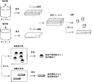
- FIG. 1 It is a schematic diagram which shows one Example of the manufacturing method of the microparticles
- the method for producing fine particles of the present invention includes a step of producing minute pieces by cutting a resin film at equal intervals of 0.05 to 500 ⁇ m in width.
- the resin film a single-layer film or a composite film having two or more layers can be used, but a composite film is preferably used.
- a composite film By using the composite film, composite fine particles having a heterogeneous surface can be produced.
- a method for producing composite fine particles having a heterogeneous hemisphere surface for example, a method called a microreactor method or a nozzle method is known as disclosed in JP-T-2001-500172.
- a microreactor method or a nozzle method is known as disclosed in JP-T-2001-500172.
- two types of droplets generated from different nozzle tips are combined, or two types of droplets are combined in a micropath in the microreactor.
- productivity is extremely low
- interface conditions and flow conditions for combining two droplets into one droplet are complicated, and a stable operation is established.
- droplets are generated using nozzles and microchannels, there is a limit to the particle size range that can be controlled.
- Droplets using nozzles and microchannels are limited.
- composite fine particles as described above can impart different physical properties in the hemispherical portion, for example, fine particles in which one hemisphere surface is black and the other hemisphere surface is white, so-called black and white dichroic poles can be used for display.
- composite fine particles in which one hemisphere surface is hydrophilic and the other hemisphere surface is hydrophobic can be used as a dispersion stabilizer as surface active particles, and can also be used as a component of composite fine particles. It is.
- the resin film can be obtained by applying a polymer-containing paste to a substrate and drying, or by applying a paste containing a polymerizable monomer to a substrate and then causing a polymerization reaction. Things can be used.
- the composite film for example, (A) What is obtained by applying a polymerization reaction after applying a paste containing a polymerizable monomer to a base resin film, (B) a paste obtained by applying a polymer-containing paste to a base resin film and drying; (C) What is obtained by laminating the above-mentioned respective layer films after producing two or more respective layer films, Is preferably used.
- (C1) A method in which at least one layer resin film and at least two layer films having a precursor film containing at least one polymerizable monomer are prepared, and the above layer films are bonded together, followed by a polymerization reaction
- (C2) A method of preparing two or more layer films having one or more layer resin films and a solvent-containing film containing one or more organic solvents, and laminating the layer films, followed by drying, Is preferably used.
- the above method is appropriately selected depending on the material used.
- (C1-1) A method of drying the organic solvent after applying a paste containing a polymer, a polymerizable monomer and an organic solvent
- (C1-2) A method of polymerizing one polymerizable monomer after applying a paste containing two different polymerizable monomers, Is preferably used.
- a method of producing the solvent-containing film of (c2) for example, (C2-1) a method of applying a polymerization reaction after applying a paste containing a polymerizable monomer and an organic solvent, Is preferably used.
- the above method is also appropriately selected depending on the material used as in the previous section.
- polymer examples include poly (meth) acrylate, polystyrene, polyvinyl chloride, polyvinylidene chloride, polyvinyl acetate, polyvinyl alcohol, polyvinyl acetal, polyethylene, polypropylene, polyamide, polyacetal, polycarbonate, saturated polyester, and polylactic acid.
- Thermosetting resins such as thermoplastic resins, polyurethanes, unsaturated polyesters, polyimides, phenol resins, urea resins, melamine resins, diallyl phthalate resins, epoxy resins, silicon resins, cellulose, polysaccharides, various fatty acid esters, gelatin, proteins, And high molecular compounds derived from natural products such as Examples of the polymerizable monomer include (meth) acrylates, styrene derivatives, vinyl chloride, vinylidene chloride, vinyl acetate, ethylene, propylene and other addition polymerizable monomers, caprolactam, dicarboxylic acid and diamine, ether and carboxylic acid, lactic acid, Examples thereof include polycondensation / polyaddition polymerizable monomers such as alkoxysilanes, urethane monomers, and epoxy monomers.
- the paste containing the polymerizable monomer preferably contains an organic solvent, water, a viscosity modifier, a surface tension modifier and the like. Moreover, you may add the substance which exhibits physical properties, such as a color, charging property, electroconductivity, thermal conductivity, a functional group, and magnetism, to the said paste containing a polymerizable monomer.
- Examples of the method for applying the paste containing the polymerizable monomer include a casting method, a bar coating method, a spin coating method, a dipping method, and an ink jet method. Moreover, when the paste containing the said polymerizable monomer contains the substance which exhibits ion exchange gelling ability or a crosslinking action, it is preferable to make it gelatinize.
- the core materials are preferably arranged at equal intervals.
- the core substance is arrange
- a pharmaceutical a hardening
- Specific examples include silver particles and an ascorbic acid aqueous solution.
- the thickness of the resin film is preferably 0.05 to 1000 ⁇ m. If the thickness is less than 0.05 ⁇ m, the strength of the film will be reduced and it may be difficult to peel off from the substrate after cutting. If it exceeds 1000 ⁇ m, the strength of the film will be too high and precision cutting will be difficult. become. More preferably, it is 0.15 to 100 ⁇ m.
- the resin film is cut at equal intervals of 0.05 to 500 ⁇ m in width.
- the cutting width is less than 0.05 ⁇ m, the particle size uniformity of the fine particles obtained even when using a precision cutting machine such as a laser is lowered.
- the cutting width exceeds 500 ⁇ m, the dispersibility of the obtained fine particles and the powder flow are reduced. Sexuality gets worse.
- a preferred lower limit is 0.15 ⁇ m and a preferred upper limit is 100 ⁇ m.
- the shape of the minute piece obtained by cutting the resin film is not particularly limited, and examples thereof include a cubic shape, a substantially cubic shape, a quadrangular prism shape, a substantially quadrangular prism shape, and a cylindrical shape.
- a method for cutting the resin film for example, a known laser cutting machine, fine cutting machine or the like can be used. In particular, an excimer laser type precision cutting machine is preferable.
- the resin film it is preferable to cut the resin film so that the core substance is located at the center of the minute piece. As a result, microcapsules having a uniform shell film thickness and high core substance retention can be obtained.
- the method for producing fine particles of the present invention it is preferable to perform a step of melting the fine piece after the step of producing the fine piece.
- the method for melting the fine pieces include a method for melting the fine pieces by heating to a temperature equal to or higher than the melting point of the resin constituting the resin film, and a solvent that is not compatible with the resin constituting the resin film.
- the method include adding and melting.
- after melting, polymerization, drying, or gelation may be further continued after forming a spherical shape.
- the resin film is a composite film
- the peeling of the composite film can be prevented, and a good heterogeneous hemispheric surface It is possible to efficiently prepare composite microparticles having
- ethylene glycol or the like can be used as the solvent.
- polyvinyl alcohol, tricalcium phosphate or the like may be added.
- FIG. 1 shows a case where composite fine particles having a heterogeneous hemispheric surface are produced using a composite film.
- the method for producing composite fine particles having two kinds of heterogeneous hemispherical surfaces includes a step of preparing a solution by dissolving or dispersing a functional expression substance in a solvent such as a polymerizable monomer, water, an organic solvent, and the like.
- a solvent such as a polymerizable monomer, water, an organic solvent, and the like.
- a composite film can also be produced by applying a solution dissolved or dispersed in a solvent such as a polymerizable monomer, water, or an organic solvent to a sheet, followed by drying or polymerization.
- a solvent such as a polymerizable monomer, water, or an organic solvent
- the particle size of the composite fine particles is determined by the thickness and cutting size of each film, the particle size control is very easy.
- the particle diameter of the composite fine particles can be controlled in the range of 0.05 to 1000 ⁇ m.
- cutting can be performed with high dimensional accuracy, and monodispersed composite fine particles having a uniform particle size distribution can be prepared.
- monodispersed composite fine particles having a uniform particle size distribution can be prepared.
- the composite film is cut into a substantially cubic shape, spherical composite fine particles can be obtained, and when the composite film is cut into a substantially quadrangular prism shape, cylindrical composite fine particles can be obtained.
- films having different physical properties are independently prepared and combined, various functions can be imparted to the respective hemispherical surfaces.
- a third component serving as a core material is coated on one film and coated, or particles of the third component are equally spaced by a one-shot injection method such as an ink jet method. And cut the composite film so that the particles of the third component are located in the center of the fine piece, and then melt the fine piece to bring the third component into the center of the spherical composite fine particles. Can be encapsulated.
- the content of the third component in the composite fine particles can be uniformly and arbitrarily controlled.
- the encapsulation efficiency of the third component can be set to 100%. Therefore, this method is suitably used when the third component is expensive.
- a core-shell microcapsule in which the shell and the core are concentric and the shell thickness is uniform can be easily prepared. Can do.
- a heterogeneous hemispherical surface with the equator of the spherical particles as the boundary surface can be formed.
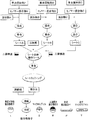
- FIG. 3 taking a case where a polymerizable monomer is used as an example.
- film is described as “sheet”.
- Polymerization initiators A, B, and C, and additives A, B, and C are added to and mixed with monomer mixtures A, B, and C made of polymerizable monomers, respectively, and polymerized for a predetermined time.
- Each of the monomer mixtures A, B, and C is poured into a petri dish to form a sheet by a casting method, and preliminary bulk polymerization is performed for a predetermined time to obtain sheets A, B, and C.
- composite sheet having a two-layer structure is prepared from the two sheets A and B, and a composite sheet having a three-layer structure is prepared from the three sheets A, B, and C.
- the composite sheet is cut into a predetermined size (sheet cutting) with a cutting machine to form fine pieces, and the fine pieces are put into a continuous phase (for example, an aqueous phase at 80 ° C.) to be melted and cooled.
- composite fine particles (I) having a heterogeneous hemispherical surface can be prepared by cutting the composite sheet having a two-layer structure into a substantially cubic shape.
- Three-layer composite fine particles (III) can be prepared by cutting a three-layer composite sheet into a substantially cubic shape.
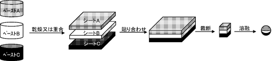
- FIG. 4 shows a case where three-layer composite fine particles are prepared by cutting a three-layer composite sheet into a substantially cubic shape.
- Columnar composite fine particles (IV) can be prepared by cutting a composite sheet having a two-layer structure into a substantially quadrangular prism shape. Further, before the two sheets A and B are bonded, a microcapsule (II) or a columnar microcapsule (V) having a heterogeneous spherical surface can be prepared by placing a core substance on one sheet. it can.
- composite fine particles having a heterogeneous surface of the present invention information recording materials (conductive-insulating, black-white, negatively charged-positively charged), stationery (black-white), pharmaceuticals (negatively charged-positively)
- Composite fine particles useful in fields such as charging, hydrophilicity-hydrophobicity), adhesives / paints (magnetic-nonmagnetic, conductive-insulating, thermal conductive-nonthermal conductive) can be produced.
- various core substances it can be used in fields such as agriculture, cosmetics, civil engineering / architecture, and food.
- high-value-added composite fine particles having uniform quality can be obtained.
- Example 1 Casting method by injecting a mixed solution of 2.5 g of polymethyl methacrylate, 2.5 g of polyisobutyl methacrylate, 5 g of MEK (methyl ethyl ketone), 5 g of butanol and 0.01 g of neogen R (sodium dodecylbenzenesulfonate) as a surfactant into a petri dish To obtain a sheet having a thickness of 50 ⁇ m.
- MEK methyl ethyl ketone
- neogen R sodium dodecylbenzenesulfonate
- this sheet was cut in a vertical and horizontal orthogonal direction with a cutting width of 50 ⁇ m (50 ⁇ m square) using an excimer laser precision cutting machine (light source ArF laser, wavelength 193 nm), and a square columnar micro piece having a size of 50 ⁇ m square.
- the obtained fine piece was put into a continuous phase at 80 ° C. and melted into a spherical shape.
- the continuous phase was prepared by dissolving 0.5 g of polyvinyl alcohol and 2.5 g of tricalcium phosphate in 100 g of ethylene glycol.
- the obtained particles had an average particle size of 55 ⁇ m and a CV value of 4%.
- Example 1 Particles were prepared in the same manner as in Example 1 except that a fine piece was prepared by crushing the sheet with a planetary ball mill (manufactured by Fritsch Japan, P-7) without using a laser cutting machine.
- the average particle diameter of the obtained particles was 35 ⁇ m, and the CV value was 112%.
- Example 2 Manufacture of black and white fine particles
- monomer mixtures A and B 5 g each of a mixture of styrene and ethylhexyl acrylate, as polymerization initiators A and B, 0.5 g each of AIBN (azobisisobutyronitrile), and as additive A, a white pigment, dioxide 0.6 g of titanium (TiO 2 ) powder, additive B, 0.5 g of magnetite (Fe 3 O 4 ) powder as a black pigment, 10 g of MEK as a solvent to be added to monomer mixtures A and B, monomer mixture Composite fine particles were produced according to the flow shown in FIG.
- Span 80 sorbitan monooriate
- Polymerization initiator A, additive A, and surfactant were added to monomer mixture A and mixed, and preliminary bulk polymerization was performed for a predetermined time. Thereafter, the mixed monomer was poured into a petri dish to form a film by a casting method, and the preliminary bulk polymerization was continued to obtain a sheet A. The thickness of the sheet A was 110 ⁇ m.
- the polymerization initiator B, additive B, and surfactant were added to the monomer mixture B and mixed, and preliminary bulk polymerization was performed for a predetermined time. Thereafter, the mixed monomer was poured into a petri dish to form a film by a casting method, and the preliminary bulk polymerization was continued to obtain a sheet B. The thickness of the sheet B was 130 ⁇ m.
- the polymerization is continued to consume the residual monomer, followed by cooling, whereby one hemisphere is black and the other hemisphere is white, an average particle diameter of 170 ⁇ m, and a CV value of 5%. was gotten.
- Example 3 In the preparation of Sheet A, Sheet A was prepared in the same manner as in Example 2 except that the mixed monomer was spin-coated on glass and then prepolymerized. The thickness of the obtained sheet A was 0.10 ⁇ m. A mixed monomer of the same monomer B as in Example 2 was spin-coated on this sheet A and subjected to heat polymerization for 10 minutes to obtain a composite sheet having a thickness of 0.19 ⁇ m.
- This composite film was cut in a vertical and horizontal orthogonal direction with a cutting width of 0.15 ⁇ m (0.15 ⁇ m square) using an excimer laser type precision cutting machine to obtain a square columnar small piece having a size of 0.15 ⁇ m square. .
- the obtained fine piece was put into a continuous phase at 80 ° C. and melted into a spherical shape.
- a continuous phase a solution in which 0.5 g of polyvinyl alcohol and 2.5 g of tricalcium phosphate were dissolved in 100 g of ethylene glycol was used.
- Example 3 the composite film was cut in a vertical and horizontal orthogonal direction with a cutting width of 1500 ⁇ m (1500 ⁇ m square) using an excimer laser type precision cutting machine, except that a square columnar micro piece having a size of 1500 ⁇ m square was obtained. Particles were produced in the same manner as in Example 2. However, the particles obtained after cooling remained flat, and a powder with extremely poor fluidity was obtained. The average particle size of the particles was 450 ⁇ m, and the CV value was 135%.
- Example 4 Particles were produced in the same manner as in Example 3 except that the composite film was cut with an excimer laser precision cutting machine with a cutting width of 0.04 ⁇ m (0.04 ⁇ m square) to obtain a fine piece. However, the particles obtained by cooling were observed to have unclear dichroic structures. The average particle size of the particles was 0.06 ⁇ m, and the CV value was 63%.
- Example 4 Manufacture of microcapsule type fine particles
- monomer mixtures A and B 5 g each of a mixture of styrene monomer and ethylhexyl acrylate, as polymerization initiators A and B, 0.5 g each of AIBN (azobisisobutyronitrile), and as core material C, silver particles and monomers
- AIBN azobisisobutyronitrile
- core material C silver particles and monomers
- Composite fine particles were produced according to the flow shown in FIG. 3 and FIG. 5 using 0.05 g of Span 80 (sorbitan monooriate) as a surfactant to be added to the mixtures A and B.
- Span 80 sorbitan monooriate
- Example 2 The same operations as in Example 2 were performed until the sheets A and B were produced. However, casting was performed so that the thicknesses of the sheet A and the sheet B were each 15 ⁇ m. Then, silver particles having a particle diameter of 3 ⁇ m were placed on the sheet A at equal intervals of 25 ⁇ m according to the interval of cutting with a cutting machine. Thereafter, two types of films, sheet A and sheet B, were laminated and polymerized for 60 minutes, and then this composite film was cut in a vertical and horizontal orthogonal direction with a cutting width of 25 ⁇ m using an excimer laser precision cutting machine ( 25 ⁇ m square) and 25 ⁇ m square size square-column-shaped microscopic pieces were obtained. The obtained fine piece was put into a continuous phase at 80 ° C.
- a solution in which 0.5 g of polyvinyl alcohol and 2.5 g of tricalcium phosphate were dissolved in 100 g of ethylene glycol was used. At this time, no silver particles were detached from the composite film into the continuous layer. Thereafter, the polymerization is continued in order to consume the residual monomer, and then cooling is performed to cool the composite fine particles having a form of microcapsules having an average particle diameter of 26 ⁇ m and a CV value of 8%, including silver particles in the center as a core substance. was gotten.
- Example 5 Microcapsule-type particles were prepared in the same manner as in Example 4 except that the arrangement of the silver particles of the core material was 5-30 ⁇ m. As a result, the silver particles were not necessarily arranged only in the center of the capsule, and silver particles that were detached from the composite film into a continuous layer were observed when the particles were spheroidized.
- Example 6 Microcapsule-type particles were prepared in the same manner as in Example 4 except that the silver particles of the core substance were arranged at regular intervals of 15 ⁇ m. As a result, the silver particles were not necessarily arranged at the center of the capsule, and silver particles that were detached from the composite film into a continuous layer were observed when the particles were spheroidized.
- Example 7 [Production of (hydrophilic-hydrophobic) amphiphilic fine particles]
- hydrophobic monomer mixture A 5.0 g of styrene, as hydrophilic monomer mixture B, 5.0 g of 2-hydroxyethyl methacrylate, and as additive A, 0.1 g of titanium dioxide (TiO 2 ) powder as a white pigment was added.
- 0.1 g of magnetite (Fe 3 O 4 ) powder as a black pigment 0.5 g of AIBN (azobisisobutyronitrile) as the polymerization initiators A and B, respectively, to the monomer mixtures A and B
- AIBN azobisisobutyronitrile
- a polymerization initiator B a solvent, and a surfactant were added to the monomer mixture B, mixed, and polymerized at 70 ° C. for a predetermined time. Thereafter, this polymer solution was poured onto a petri dish A and formed into a film by a casting method, and a sheet B was laminated to prepare a composite film having a thickness of 43 ⁇ m. The thickness of the sheet B portion was 20 ⁇ m.
- this composite film was cut in a vertical and horizontal orthogonal direction with a cutting width of 100 ⁇ m (100 ⁇ m square) using an excimer laser type precision cutting machine to obtain a square columnar micro piece having a size of 100 ⁇ m square.
- This fine piece was put into a continuous phase at 80 ° C. and melted into a spherical shape.
- a continuous phase a solution in which 0.5 g of polyvinyl alcohol and 2.5 g of tricalcium phosphate were dissolved in 100 g of water was used.
- two-color composite fine particles having an average particle diameter of 41 ⁇ m and a CV value of 4%, in which one hemisphere was black and the other hemisphere was white, were obtained.
- Example 8 [Production of (hydrophilic-hydrophobic) amphiphilic fine particles]
- the hydrophobic paste mixture A 5.0 g of polystyrene, 0.1 g of titanium dioxide (TiO 2 ) powder as a white pigment, 10 g of MEK as a solvent, 0.05 g of Span 80 (sorbitan monooriate) as a surfactant Using. After injecting the paste mixture A into a petri dish, the solvent was dried at 70 ° C., and a film was formed by a casting method to obtain a hydrophobic sheet A. The thickness of the sheet A was 53 ⁇ m.
- hydrophilic paste mixture B 5.0 g of hydroxypropyl methylcellulose (Metroze 60SH manufactured by Shin-Etsu Chemical Co., Ltd.), 0.1 g of magnetite (Fe 3 O 4 ) powder as a black pigment, 10 g of ion-exchanged water as a solvent, interface As an activator, 0.05 g of Span 80 (sorbitan monooriate) was used. After injecting the paste mixture B into a petri dish, the solvent was dried at 70 ° C., and a film was formed by a casting method to obtain a hydrophilic sheet B. The thickness of the sheet B was 45 ⁇ m.
- Example 9 [Production of (hydrophilic-hydrophobic) amphiphilic fine particles]
- the hydrophobic paste mixture A 2.5 g of styrene, 2.5 g of polystyrene, 0.1 g of titanium dioxide (TiO 2 ) powder as a white pigment, and 0.1 wt.
- AIBN azobisisobutyronitrile
- 3 g 10 g of MEK as a solvent, and 0.05 g of Span 80 (sorbitan monooriate) as a surfactant were used.
- the solvent was dried at 50 ° C. and formed into a film by a casting method to obtain a hydrophobic sheet A.
- the thickness of the sheet A was 55 ⁇ m.
- the hydrophilic paste mixture B hydroxypropylmethylcellulose (Metrouse 60SH manufactured by Shin-Etsu Chemical Co., Ltd.) 5.0 g, black pigment magnetite (Fe 3 O 4 ) powder 0.1 g, ion-exchanged water 10 g as a solvent, interface As an activator, 0.05 g of Span 80 (sorbitan monooriate) was used. After injecting the paste mixture B into a petri dish, the solvent was dried at 70 ° C., and a film was formed by a casting method to obtain a hydrophilic sheet B. The thickness of the sheet B was 48 ⁇ m.
- the present invention it is possible to provide a method for producing fine particles in which fine particles having a uniform particle size distribution that can be arbitrarily controlled in particle size can be obtained by a simple method with little environmental load. Further, there is provided a method for producing composite fine particles having a heterogeneous surface, which is highly productive and has no limitation on the foreign substances that can be added for function expression, and further can include foreign substances at the center of the spheres of the composite fine particles. be able to.
Landscapes
- Engineering & Computer Science (AREA)
- Mechanical Engineering (AREA)
- Optics & Photonics (AREA)
- Chemical & Material Sciences (AREA)
- Physics & Mathematics (AREA)
- Plasma & Fusion (AREA)
- Medicinal Chemistry (AREA)
- Polymers & Plastics (AREA)
- Organic Chemistry (AREA)
- Chemical Kinetics & Catalysis (AREA)
- Health & Medical Sciences (AREA)
- Processes Of Treating Macromolecular Substances (AREA)
- Manufacturing Of Micro-Capsules (AREA)
- Manufacture Of Macromolecular Shaped Articles (AREA)
Abstract
Description
また、懸濁重合法は疎水性のモノマーを機械的な攪拌によって、懸濁させ、液滴をそのまま樹脂粒子化する方法であり、数μmから数十μmの樹脂微粒子を得ることができる。
更に、分散重合法は有機溶剤中でのソープフリー乳化重合法といえる方法であり、サブミクロンから数μmの粒子径の樹脂微粒子を得るのに適している。
また、従来の方法では、粒度分布が均一な微粒子を製造することは困難であった。
一方、超臨界技術を用いた噴出法により微小な樹脂粒子を製造する技術(RESS法)では、超臨界二酸化炭素を使用するため、乾燥工程が不要で、環境負荷が低いという利点を有している。しかし、予め重合したポリマーを超臨界二酸化炭素に溶解させる必要があり、一般に超臨界二酸化炭素に対するポリマーの溶解度は低いため、RESS法には生産性に課題があった。
また、生産性が高く、機能発現のために添加できる異種物質に制限がなく、さらに、複合微粒子の球体中心に異種物質を包含させることができる、異質表面を有する複合微粒子の製造方法を提供することができる。
上記複合フィルムを用いることで、異質表面を有する複合微粒子を製造することができる。
しかしながら、本発明の方法を用いることにより、上記(i)~(v)の問題を解決することが可能となる。
(a)重合性モノマーを含有するペーストを基材樹脂フィルムに塗工した後、重合反応させることにより得られるもの、
(b)ポリマーを含有するペーストを基材樹脂フィルムに塗工、乾燥することにより得られるもの、
(c)2以上の各層フィルムを作製した後、上記各層フィルムを貼り合せることにより得られるもの、
を用いることが好ましい。
(c1)1以上の各層樹脂フィルムと、1以上の重合性モノマーを含有する前駆体フィルムと有する2以上の各層フィルムを作製し、上記各層フィルムを貼り合せた後、重合反応させる方法、
(c2)1以上の各層樹脂フィルムと、1以上の有機溶剤を含有する溶剤含有フィルムと有する2以上の各層フィルムを作製し、上記各層フィルムを貼り合せた後、乾燥する方法、
を用いることが好ましい。
上記方法は、用いられる原料の材質によって適宜選択される。例えば、重合性モノマーを用いる場合は、フィルムを貼り合せた後に重合することによって、強固な貼り合せ界面が形成されるので、(c1)の方法が好ましく、天然由来のポリマーを原料に用いる場合は(c2)の方法が好ましい。
(c1-1)ポリマー、重合性モノマー及び有機溶剤を含有するペーストを塗工した後、上記有機溶剤を乾燥する方法、
(c1-2)異なる2種の重合性モノマーを含有するペーストを塗工した後、一方の重合性モノマーを重合させる方法、
を用いることが好ましい。
また、上記(c2)の溶剤含有フィルムを作製する方法としては、例えば、
(c2-1)重合性モノマー及び有機溶剤を含有するペーストを塗工した後、重合反応させる方法、
を用いることが好ましい。
上記の方法についても、前項と同様に、用いられる原料の材質によって適宜選択される。
上記重合性モノマーとしては、例えば、(メタ)アクリレート、スチレン誘導体、塩化ビニル、塩化ビニリデン、酢酸ビニル、エチレン、プロピレン等の付加重合性モノマー、カプロラクタム、ジカルボン酸とジアミン、エーテルとカルボン酸、乳酸、アルコキシシラン、ウレタンモノマー、エポキシモノマー等の重縮合・重付加重合性モノマー等が挙げられる。
また、上記重合性モノマーを含有するペーストには、色彩、帯電性、導電性、熱伝導性、官能基、磁性等の物性を呈する物質を添加してもよい。
また、上記重合性モノマーを含有するペーストがイオン交換ゲル化能や架橋作用を呈する物質を含む場合はゲル化させることが好ましい。
また、上記樹脂フィルムが複合フィルムである場合は、層間に芯物質が等間隔で配置されていることが好ましい。
上記芯物質が等間隔で配置されていることで、例えば、異質球面をもつマイクロカプセルや柱状マイクロカプセルを作製することができる。
厚みが0.05μm未満であると、フィルムの強度が小さくなり、裁断後に基材から剥離するのが困難になることがあり、1000μmを超えると、フィルムの強度が大きくなりすぎて精密裁断が困難になる。より好ましくは0.15~100μmである。
上記切断幅が0.05μm未満であると、レーザー等の精密な裁断機を用いても得られる微粒子の粒子径均一性が低くなり、500μmを超えると、得られる微粒子の分散性や粉体流動性が悪くなる。好ましい下限は0.15μm、好ましい上限は100μmである。
なお、上記切断の方法としては、樹脂フィルムの長手方向に等間隔で切断してもよく、樹脂フィルムの長手方向と垂直方向に等間隔で切断してもよい。また、切断面が正方形になるように切断してもよく、矩形状や円形になるように切断してもよい。
更に、上記幅0.05~500μmの等間隔で切断した後、更に切断面と垂直方向に切断してもよい。
上記微小片を溶融する方法としては、例えば、上記微小片を、樹脂フィルムを構成する樹脂の融点以上の温度に加熱して溶融する方法や、樹脂フィルムを構成する樹脂と相溶性のない溶媒に添加して溶融する方法等が挙げられる。
なお、溶融した後、球状としてから重合、乾燥、又はゲル化をさらに継続してもよい。特に、樹脂フィルムが複合フィルムである場合は、樹脂フィルム調製前の重合反応時間と、樹脂フィルム調製後の重合反応時間とを調整することで、複合フィルムの剥離を防止でき、良好な異質半球表面を有する複合微粒子を効率良く調製することができる。
また、図2に示すように、重合性モノマー、水、有機溶媒などの溶媒に溶解或いは分散させた溶液をシートに塗工した後、乾燥又は重合させることで複合フィルムを作製することもできる。
また、異なる物性のフィルムを独自に調製し、これを合体させることから、それぞれの半球表面に多種多様な機能を付与することができる。
つぎに、複合シートを切断機で所定の大きさに切断(シートカッティング)して微小片とし、この微小片を連続相(例えば80℃の水相)中に投入して溶融、冷却する。ここで、二層構造の複合シートを略立方体形状に切断することにより、異質半球面をもつ複合微粒子(I)を調製することができる。三層構造の複合シートを略立方体形状に切断することにより、三層構造複合微粒子(III)を調製することができる。なお、図4に、三層構造の複合シートを略立方体形状に切断することにより、三層構造複合微粒子を調製する場合を示す。
二層構造の複合シートを略四角柱形状に切断することにより、柱状複合微粒子(IV)を調製することができる。また、2枚のシートA、Bを貼り合せる前に、一方のシート上に芯物質を載置することにより、異質球面をもつマイクロカプセル(II)や柱状マイクロカプセル(V)を調製することができる。
ポリメチルメタクリレート2.5g、ポリイソブチルメタクリレート2.5g、MEK(メチルエチルケトン)5g、ブタノール5g、界面活性剤としてネオゲンR(ドデシルベンゼンスルホン酸ナトリウム)0.01gの混合溶液をシャーレに注入してキャスト法にてフィルム化し、厚み50μmのシートを得た。
次いで、このシートをエキシマレーザー式精密切断機(光源ArFレーザー、波長193nm)を用いて、切断幅50μmで縦横直交方向に切断し(50μm角)、50μm角の大きさの四角柱形状の微小片を得た。
得られた微小片を80℃の連続相中に投入して溶融して球状にした。ここで、連続相としては、エチレングリコール100gにポリビニルアルコール0.5gとリン酸三カルシウム2.5gを溶解したものを用いた。得られた粒子の平均粒子径は55μm、CV値は4%であった。
レーザー式切断機を用いず、シートを遊星ボールミル(フリッチュジャパン社製、P-7)で粉砕することにより、微小片を作製した以外は、実施例1と同様の方法で粒子を作成した。得られた粒子の平均粒子径は35μm、CV値は112%であった。
ポリメチルメタクリレート2.5g、ポリイソブチルメタクリレート2.5g、MEK(メチルエチルケトン)25g、ブタノール25gを含有する混合溶液をラボ噴霧乾燥機(日本ビュッヒ社製、B-290)を用いて乾燥粉体化した。得られた粒子の平均粒子径は30μm、CV値は45%であった。
[白黒微粒子の製造]
モノマー混合物A,Bとして、スチレンとエチルヘキシルアクリレートの混合物をそれぞれ5g、重合開始剤A,Bとして、AIBN(アゾビスイソブチロニトリル)をそれぞれ0.5g、添加物Aとして、白色顔料である二酸化チタン(TiO2)粉末を0.6g、添加物Bとして、黒色顔料であるマグネタイト(Fe3O4)粉末を0.5g、モノマー混合物A,Bに添加する溶媒としてMEKをそれぞれ10g、モノマー混合物A,Bに添加する界面活性剤として、Span80(ソルビタンモノオリエート)をそれぞれ0.05g用いて、図2に示すフローに従って複合微粒子を製造した。
モノマー混合物Aに重合開始剤A、添加物A、界面活性剤を加えて混合し、所定時間予備塊状重合した。その後、この混合モノマーをシャーレに注入してキャスト法にてフィルム化し、さらに予備塊状重合を継続し、シートAを得た。シートAの厚みは110μmであった。同様に、モノマー混合物Bに重合開始剤B、添加物B、界面活性剤を加えて混合し、所定時間、予備塊状重合した。その後、この混合モノマーをシャーレに注入してキャスト法にてフィルム化し、さらに予備塊状重合を継続し、シートBを得た。シートBの厚みは130μmであった。
次いで、この複合フィルムをエキシマレーザー式精密切断機を用いて、切断幅150μmで縦横直交方向に切断し(150μm角)、150μm角の大きさの四角柱形状の微小片を得た。この微小片を80℃の連続相中に投入して溶融して球状にした。ここで、連続相として、エチレングリコール100gにポリビニルアルコール0.5gとリン酸三カルシウム2.5gを溶解したものを用いた。
シートAの作製において、混合モノマーをガラス上にスピンコートした後、予備重合した以外は、実施例2と同様にしてシートAを作製した。得られたシートAの厚みは0.10μmであった。このシートAの上に、実施例2と同様のモノマーBの混合モノマーをスピンコートし、10分間加熱重合を行うことによって、厚み0.19μmの複合シートを得た。
実施例2において、複合フィルムをエキシマレーザー式精密切断機を用いて、切断幅1500μmで縦横直交方向に切断し(1500μm角)、1500μm角の大きさの四角柱形状の微小片を得た以外は実施例2と同様にして粒子を作製した。しかしながら、冷却後に得られた粒子は扁平状のままであり、流動性が著しく劣る粉体が得られた。なお、粒子の平均粒子径は450μm、CV値は135%であった。
複合フィルムをエキシマレーザー式精密切断機を用いて、切断幅0.04μm(0.04μm角)で切断することで微小片を得た以外は実施例3と同様にして粒子を作製した。
しかしながら、冷却することにより得られた粒子は、二色構造が不鮮明な粒子が観察された。なお、粒子の平均粒子径は0.06μm、CV値は63%であった。
[マイクロカプセル型微粒子の製造]
モノマー混合物A,Bとして、スチレンモノマーとエチルヘキシルアクリレートの混合物をそれぞれ5g、重合開始剤A,Bとして、AIBN(アゾビスイソブチロニトリル)をそれぞれ0.5g、芯物質Cとして、銀粒子、モノマー混合物A,Bに添加する界面活性剤として、Span80(ソルビタンモノオリエート)をそれぞれ0.05g用いて、図3に示すフロー及び図5に従って複合微粒子を製造した。
その後、残存モノマーを消費するために重合を継続した後、冷却することにより、芯物質として銀粒子を中心部に包含した、平均粒子径26μm、CV値8%のマイクロカプセルの形態を有する複合微粒子が得られた。
芯物質の銀粒子の配置において、5~30μmの不均一な間隔としたこと以外は実施例4と同様にマイクロカプセル型粒子を作成した。その結果、銀粒子は必ずしもカプセルの中心部のみに配置せず、粒子を球状化する際、複合フィルムから連続層に脱離する銀粒子が観察された。
芯物質の銀粒子の配置において、15μmの等間隔としたこと以外は実施例4と同様にマイクロカプセル型粒子を作成した。その結果、銀粒子は必ずしもカプセルの中心部には配置せず、粒子を球状化する際、複合フィルムから連続層に脱離する銀粒子が観察された。
[(親水性-疎水性)両親媒性微粒子の製造]
疎水性モノマー混合物Aとして、スチレン5.0g、親水性モノマー混合物Bとして、2-ヒドロキエチルメタクリレート5.0g、添加物Aとして、白色顔料である二酸化チタン(TiO2)粉末を0.1g、添加物Bとして、黒色顔料であるマグネタイト(Fe3O4)粉末を0.1g、重合開始剤A、Bとして、AIBN(アゾビスイソブチロニトリル)をそれぞれ0.5g、モノマー混合物A、Bに添加する溶媒としてMEKをそれぞれ10g、モノマー混合物A、Bに添加する界面活性剤として、Span80(ソルビタンモノオリエート)をそれぞれ0.05g用いて、図3に示すフローに従って複合微粒子を製造した。
即ち、モノマー混合物Aに重合開始剤A、溶媒、界面活性剤を加えて混合し、70℃にて所定時間重合した。その後、このポリマー溶液をシャーレに注入してキャスト法にて溶剤を乾燥しながらフィルム化し、疎水性シートAを得た。シートAの厚みは23μmであった。同様に、モノマー混合物Bに重合開始剤B、溶剤、界面活性剤を加えて混合し、70℃にて所定時間重合した。その後、このポリマー溶液をシャーレのシートA上に注入してキャスト法にてフィルム化し、シートBを積層して厚み43μmの複合フィルムを作製した。シートB部分の厚みは20μmであった。
この粒子が分散したスラリーに、ヘキサン100gを添加し、攪拌した後一時間静置して観察すると、粒子は水とヘキサンの界面に局在し、粒子の白い疎水性部分はヘキサン層に、粒子の黒い親水性部分は水と接するように配置されているのが観察され、両親媒性粒子であることが確認された。
[(親水性-疎水性)両親媒性微粒子の製造]
疎水性ペースト混合物Aとして、ポリスチレン5.0g、白色顔料である二酸化チタン(TiO2)粉末を0.1g、溶媒としてMEKを10g、界面活性剤として、Span80(ソルビタンモノオリエート)を0.05g用いた。ペースト混合物Aをシャーレに注入したのち、70℃にて溶剤を乾燥し、キャスト法にてフィルム化し、疎水性シートAを得た。シートAの厚みは53μmであった。
他方、親水性ペースト混合物Bとして、ヒドロキシプロピルメチルセルロース(信越化学社製メトローズ60SH)5.0g、黒色顔料であるマグネタイト(Fe3O4)粉末を0.1g、溶媒としてイオン交換水を10g、界面活性剤として、Span80(ソルビタンモノオリエート)を0.05g用いた。ペースト混合物Bをシャーレに注入したのち、70℃にて溶媒を乾燥し、キャスト法にてフィルム化し、親水性シートBを得た。シートBの厚みは45μmであった。
次いで、この複合フィルムをエキシマレーザー式精密切断機を用いて、切断幅80μmで縦横直交方向に切断し(80μm角)、80μm角の大きさの四角柱形状の微小片を得た。この微小片を80℃の連続相中に投入して溶融して球状にした。ここで、連続相として、水100gにポリビニルアルコール0.5gとリン酸三カルシウム2.5gを溶解したものを用いた。
[(親水性-疎水性)両親媒性微粒子の製造]
疎水性ペースト混合物Aとして、スチレン2.5g、ポリスチレン2.5g、白色顔料である二酸化チタン(TiO2)粉末を0.1g、重合開始剤として、AIBN(アゾビスイソブチロニトリル)を0.3g、溶媒としてMEKを10g、界面活性剤として、Span80(ソルビタンモノオリエート)を0.05g用いた。ペースト混合物Aをシャーレに注入したのち、50℃にて溶剤を乾燥し、キャスト法にてフィルム化し、疎水性シートAを得た。シートAの厚みは55μmであった。
一方、親水性ペースト混合物Bとして、ヒドロキシプロピルメチルセルロース(信越化学社製メトローズ60SH)5.0g、黒色顔料であるマグネタイト(Fe3O4)粉末を0.1g、溶媒としてイオン交換水を10g、界面活性剤として、Span80(ソルビタンモノオリエート)を0.05g用いた。ペースト混合物Bをシャーレに注入したのち、70℃にて溶媒を乾燥し、キャスト法にてフィルム化し、親水性シートBを得た。シートBの厚みは48μmであった。
次いで、この複合フィルムをエキシマレーザー式精密切断機を用いて、切断幅80μmで縦横直交方向に切断し(80μm角)、80μm角の大きさの四角柱形状の微小片を得た。この微小片を80℃の連続相中に投入して溶融して球状にした。ここで、連続相として、水100gにポリビニルアルコール0.5gとリン酸三カルシウム2.5gを溶解したものを用いた。
また、生産性が高く、機能発現のために添加できる異種物質に制限がなく、さらに、複合微粒子の球体中心に異種物質を包含させることができる、異質表面を有する複合微粒子の製造方法を提供することができる。
Claims (16)
- 樹脂フィルムを幅0.05~500μmの等間隔で切断することで微小片を作製する工程を有することを特徴とする微粒子の製造方法。
- 微小片を作製する工程を行った後、前記微小片を溶融する工程を行うことを特徴とする請求項1記載の微粒子の製造方法。
- 前記樹脂フィルムは、基材にポリマーを含有するペーストを塗工、乾燥することにより得られることを特徴とする請求項1又は2記載の微粒子の製造方法。
- 前記樹脂フィルムは、基材に重合性モノマーを含有するペーストを塗工した後、重合反応させることにより得られることを特徴とする請求項1又は2記載の微粒子の製造方法。
- 前記樹脂フィルムは、2層以上の層を有する複合フィルムであることを特徴とする請求項1、2、3又は4記載の微粒子の製造方法。
- 前記複合フィルムは、重合性モノマーを含有するペーストを基材樹脂フィルムに塗工した後、重合反応させることにより得られるものであることを特徴とする請求項5記載の微粒子の製造方法。
- 前記複合フィルムは、ポリマーを含有するペーストを基材樹脂フィルムに塗工、乾燥することにより得られるものであることを特徴とする請求項5記載の微粒子の製造方法。
- 前記複合フィルムは、2以上の各層フィルムを作製した後、前記各層フィルムを貼り合せることにより得られるものであることを特徴とする請求項5記載の微粒子の製造方法。
- 前記複合フィルムは、1以上の各層樹脂フィルムと、1以上の重合性モノマーを含有する前駆体フィルムと有する2以上の各層フィルムを作製し、前記各層フィルムを貼り合せた後、重合反応させることにより得られるものであることを特徴とする請求項8記載の微粒子の製造方法。
- 前記前駆体フィルムは、ポリマー、重合性モノマー及び有機溶剤を含有するペーストを塗工した後、前記有機溶剤を乾燥することにより得られるものであることを特徴とする請求項9記載の微粒子の製造方法。
- 前記前駆体フィルムは、異なる2種の重合性モノマーを含有するペーストを塗工した後、一方の重合性モノマーを重合させることにより得られるものであることを特徴とする請求項9記載の微粒子の製造方法。
- 前記複合フィルムは、1以上の各層樹脂フィルムと、1以上の有機溶剤を含有する溶剤含有フィルムと有する2以上の各層フィルムを作製し、前記各層フィルムを貼り合せた後、乾燥することにより得られるものであることを特徴とする請求項8記載の微粒子の製造方法。
- 前記溶剤含有フィルムは、重合性モノマー及び有機溶剤を含有するペーストを塗工した後、重合反応させることにより得られるものであることを特徴とする請求項12記載の微粒子の製造方法。
- 前記樹脂フィルムは、芯物質が等間隔で配置されていることを特徴とする請求項1、2、3、4、5、6、7、8、9、10、11、12又は13記載の微粒子の製造方法。
- 前記複合フィルムは、層間に芯物質が等間隔で配置されていることを特徴とする請求項5、6、7、8、9、10、11、12、13又は14記載の微粒子の製造方法。
- 前記微小片の中心に前記芯物質が位置するように前記樹脂フィルムを切断することを特徴とする請求項14又は15記載の微粒子の製造方法。
Priority Applications (5)
| Application Number | Priority Date | Filing Date | Title |
|---|---|---|---|
| KR1020137024190A KR20140050591A (ko) | 2011-07-26 | 2012-07-26 | 미립자의 제조 방법 |
| JP2012549189A JP5935189B2 (ja) | 2011-07-26 | 2012-07-26 | 微粒子の製造方法 |
| US14/124,818 US20140197564A1 (en) | 2011-07-26 | 2012-07-26 | Method for producing fine particles |
| CN201280022647.3A CN103517938A (zh) | 2011-07-26 | 2012-07-26 | 微粒的制造方法 |
| EP12818446.2A EP2738201A4 (en) | 2011-07-26 | 2012-07-26 | PROCESS FOR PRODUCING FINE PARTICLES |
Applications Claiming Priority (2)
| Application Number | Priority Date | Filing Date | Title |
|---|---|---|---|
| JP2011163578 | 2011-07-26 | ||
| JP2011-163578 | 2011-07-26 |
Publications (1)
| Publication Number | Publication Date |
|---|---|
| WO2013015352A1 true WO2013015352A1 (ja) | 2013-01-31 |
Family
ID=47601190
Family Applications (1)
| Application Number | Title | Priority Date | Filing Date |
|---|---|---|---|
| PCT/JP2012/068943 Ceased WO2013015352A1 (ja) | 2011-07-26 | 2012-07-26 | 微粒子の製造方法 |
Country Status (7)
| Country | Link |
|---|---|
| US (1) | US20140197564A1 (ja) |
| EP (1) | EP2738201A4 (ja) |
| JP (1) | JP5935189B2 (ja) |
| KR (1) | KR20140050591A (ja) |
| CN (1) | CN103517938A (ja) |
| TW (1) | TWI567116B (ja) |
| WO (1) | WO2013015352A1 (ja) |
Families Citing this family (1)
| Publication number | Priority date | Publication date | Assignee | Title |
|---|---|---|---|---|
| ITTO20130284A1 (it) * | 2013-04-09 | 2014-10-10 | Fond Istituto Italiano Di Tecnologia | Procedimento per la produzione di microparticelle polimeriche sagomate |
Citations (10)
| Publication number | Priority date | Publication date | Assignee | Title |
|---|---|---|---|---|
| JPH10315230A (ja) * | 1997-05-19 | 1998-12-02 | Fudoo Kk | 粒状化熱硬化性樹脂成形材料の製造方法 |
| JPH11222602A (ja) * | 1998-02-04 | 1999-08-17 | Reiko Co Ltd | 金属粉製造用フイルム及び金属粉 |
| JPH11286012A (ja) * | 1998-04-01 | 1999-10-19 | Sumitomo Bakelite Co Ltd | 顆粒状半導体封止用エポキシ樹脂組成物の製造方法及び半導体装置 |
| JP2000239394A (ja) * | 1999-02-24 | 2000-09-05 | Reiko Co Ltd | 光輝性樹脂ペレット |
| JP2001500172A (ja) | 1996-07-19 | 2001-01-09 | イー インク コーポレイション | 電子的にアドレス指定可能なマイクロカプセル化されたインクおよびそのディスプレイ |
| JP2005008656A (ja) * | 2003-06-16 | 2005-01-13 | Reiko Co Ltd | 抗菌性を有する光輝性樹脂ペレット |
| JP2005239915A (ja) | 2004-02-27 | 2005-09-08 | Mitsubishi Materials Corp | 親水性を有する高分子微粒子の製造方法及びその製造装置 |
| JP2007091991A (ja) * | 2005-09-30 | 2007-04-12 | Sumitomo Chemical Co Ltd | 非互着性ゴム組成物ペレット、及びその製造方法 |
| JP2011105953A (ja) | 2011-03-02 | 2011-06-02 | Tokuyama Dental Corp | 有機無機複合フィラー |
| WO2011092955A1 (ja) * | 2010-01-27 | 2011-08-04 | 国立大学法人新潟大学 | 異質表面を有する複合微粒子の製造方法 |
Family Cites Families (8)
| Publication number | Priority date | Publication date | Assignee | Title |
|---|---|---|---|---|
| JPS5624112A (en) * | 1979-08-03 | 1981-03-07 | Daicel Chem Ind Ltd | Cutting method for specific layer of filmy synthetic resin laminate |
| JPH07156569A (ja) * | 1993-12-10 | 1995-06-20 | Ricoh Co Ltd | クリームハンダ用マスクおよびその製造方法 |
| JP2002100825A (ja) * | 2000-09-26 | 2002-04-05 | Komatsu Ltd | エキシマレーザ装置及びシリコン切断装置 |
| JP2002122893A (ja) * | 2000-10-18 | 2002-04-26 | Fujitsu Ltd | 表示デバイス用2色ボールの製造方法 |
| US20090081460A1 (en) * | 2002-09-13 | 2009-03-26 | Jds Uniphase Corporation | Reinforced Glitter |
| JP4233999B2 (ja) * | 2003-12-25 | 2009-03-04 | 日東電工株式会社 | 積層型偏光板およびその製造方法 |
| JP5269334B2 (ja) * | 2007-03-29 | 2013-08-21 | 三菱化学株式会社 | 均一粒子状ポリマーの製造方法および均一粒子状ポリマーの造粒装置 |
| JP2013018964A (ja) * | 2011-06-17 | 2013-01-31 | Nitto Denko Corp | 粘着フィルム |
-
2012
- 2012-07-26 JP JP2012549189A patent/JP5935189B2/ja not_active Expired - Fee Related
- 2012-07-26 US US14/124,818 patent/US20140197564A1/en not_active Abandoned
- 2012-07-26 EP EP12818446.2A patent/EP2738201A4/en not_active Withdrawn
- 2012-07-26 TW TW101126979A patent/TWI567116B/zh not_active IP Right Cessation
- 2012-07-26 WO PCT/JP2012/068943 patent/WO2013015352A1/ja not_active Ceased
- 2012-07-26 KR KR1020137024190A patent/KR20140050591A/ko not_active Withdrawn
- 2012-07-26 CN CN201280022647.3A patent/CN103517938A/zh active Pending
Patent Citations (10)
| Publication number | Priority date | Publication date | Assignee | Title |
|---|---|---|---|---|
| JP2001500172A (ja) | 1996-07-19 | 2001-01-09 | イー インク コーポレイション | 電子的にアドレス指定可能なマイクロカプセル化されたインクおよびそのディスプレイ |
| JPH10315230A (ja) * | 1997-05-19 | 1998-12-02 | Fudoo Kk | 粒状化熱硬化性樹脂成形材料の製造方法 |
| JPH11222602A (ja) * | 1998-02-04 | 1999-08-17 | Reiko Co Ltd | 金属粉製造用フイルム及び金属粉 |
| JPH11286012A (ja) * | 1998-04-01 | 1999-10-19 | Sumitomo Bakelite Co Ltd | 顆粒状半導体封止用エポキシ樹脂組成物の製造方法及び半導体装置 |
| JP2000239394A (ja) * | 1999-02-24 | 2000-09-05 | Reiko Co Ltd | 光輝性樹脂ペレット |
| JP2005008656A (ja) * | 2003-06-16 | 2005-01-13 | Reiko Co Ltd | 抗菌性を有する光輝性樹脂ペレット |
| JP2005239915A (ja) | 2004-02-27 | 2005-09-08 | Mitsubishi Materials Corp | 親水性を有する高分子微粒子の製造方法及びその製造装置 |
| JP2007091991A (ja) * | 2005-09-30 | 2007-04-12 | Sumitomo Chemical Co Ltd | 非互着性ゴム組成物ペレット、及びその製造方法 |
| WO2011092955A1 (ja) * | 2010-01-27 | 2011-08-04 | 国立大学法人新潟大学 | 異質表面を有する複合微粒子の製造方法 |
| JP2011105953A (ja) | 2011-03-02 | 2011-06-02 | Tokuyama Dental Corp | 有機無機複合フィラー |
Non-Patent Citations (1)
| Title |
|---|
| See also references of EP2738201A4 * |
Also Published As
| Publication number | Publication date |
|---|---|
| TW201313787A (zh) | 2013-04-01 |
| JPWO2013015352A1 (ja) | 2015-02-23 |
| KR20140050591A (ko) | 2014-04-29 |
| US20140197564A1 (en) | 2014-07-17 |
| TWI567116B (zh) | 2017-01-21 |
| JP5935189B2 (ja) | 2016-06-15 |
| EP2738201A4 (en) | 2015-03-04 |
| EP2738201A1 (en) | 2014-06-04 |
| CN103517938A (zh) | 2014-01-15 |
Similar Documents
| Publication | Publication Date | Title |
|---|---|---|
| Esser-Kahn et al. | Triggered release from polymer capsules | |
| US5556583A (en) | Encapsulation method | |
| Hwang et al. | Production of uniform-sized polymer core− shell microcapsules by coaxial electrospraying | |
| KR870008976A (ko) | 안료 캡슐화 라텍스 수성착색제 분산액 | |
| JPWO1999043758A1 (ja) | 熱膨張性マイクロカプセルとその製造方法及びその利用方法 | |
| Chang et al. | Application and prospect of self-healing microcapsules in surface coating of wood | |
| KR20130038455A (ko) | 균일한 입도를 갖는 디스플레이용 마이크로캡슐 제조 방법 | |
| Fujii | Foams/bubbles stabilized with polymer particles | |
| JP5935189B2 (ja) | 微粒子の製造方法 | |
| KR101285210B1 (ko) | 구상 복합 조성물 및 구상 복합 조성물의 제조 방법 | |
| Marino et al. | Emergent properties from three-dimensional assemblies of (nano) particles in confined spaces | |
| JP5709268B2 (ja) | 異質表面を有する複合微粒子の製造方法 | |
| CN103360529A (zh) | 一种微米级单分散聚苯乙烯微球的可控合成方法 | |
| KR20150017796A (ko) | 나노입자를 포함하는 액상 마이크로 캡슐의 제조방법 | |
| CN108297438A (zh) | 一种基于光诱导可逆胶束的3d打印支撑材料的制备方法 | |
| Lee et al. | Fabrication of kinetically stable micropolymofoam particles and the spontaneous induction of morphological transformation | |
| CN101519472A (zh) | 一种用于制备中空微胶囊囊壁的组合物及制备方法 | |
| JP2004300436A (ja) | 樹脂微粒子の製造方法及び樹脂微粒子、それを装填した物品 | |
| WO2001064331A1 (de) | Verfahren zur herstellung von mikro- und/oder nanokapseln | |
| Fan et al. | Preparation of oil core/polyelectrolyte shell microcapsules by a coacervation method | |
| CN102085469B (zh) | 微纳米级粉体借助界面聚合制备大粒径颗粒的方法 | |
| CN108079915A (zh) | 一种基于基材与壳材粒度双调控的微胶囊材料的制备方法及装置 | |
| JPH04290539A (ja) | マイクロカプセル複合体およびその製造方法 | |
| CN102617757B (zh) | 一种制备聚合物纳米颗粒的方法 | |
| JP2004091767A (ja) | 微粒子状光硬化性樹脂の製造方法、微粒子状光硬化性樹脂および物品の表面処理方法 |
Legal Events
| Date | Code | Title | Description |
|---|---|---|---|
| ENP | Entry into the national phase |
Ref document number: 2012549189 Country of ref document: JP Kind code of ref document: A |
|
| 121 | Ep: the epo has been informed by wipo that ep was designated in this application |
Ref document number: 12818446 Country of ref document: EP Kind code of ref document: A1 |
|
| ENP | Entry into the national phase |
Ref document number: 20137024190 Country of ref document: KR Kind code of ref document: A |
|
| NENP | Non-entry into the national phase |
Ref country code: DE |
|
| WWE | Wipo information: entry into national phase |
Ref document number: 2012818446 Country of ref document: EP |
|
| WWE | Wipo information: entry into national phase |
Ref document number: 14124818 Country of ref document: US |