WO2013018226A1 - Procédé de façonnage de bouton pression, élément intermédiaire de fixation et fixation à pression - Google Patents
Procédé de façonnage de bouton pression, élément intermédiaire de fixation et fixation à pression Download PDFInfo
- Publication number
- WO2013018226A1 WO2013018226A1 PCT/JP2011/067884 JP2011067884W WO2013018226A1 WO 2013018226 A1 WO2013018226 A1 WO 2013018226A1 JP 2011067884 W JP2011067884 W JP 2011067884W WO 2013018226 A1 WO2013018226 A1 WO 2013018226A1
- Authority
- WO
- WIPO (PCT)
- Prior art keywords
- snap
- female
- male
- peripheral side
- side portion
- Prior art date
- Legal status (The legal status is an assumption and is not a legal conclusion. Google has not performed a legal analysis and makes no representation as to the accuracy of the status listed.)
- Ceased
Links
Images








Classifications
-
- A—HUMAN NECESSITIES
- A44—HABERDASHERY; JEWELLERY
- A44B—BUTTONS, PINS, BUCKLES, SLIDE FASTENERS, OR THE LIKE
- A44B17/00—Press-button or snap fasteners
- A44B17/0064—Details
- A44B17/0088—Details made from sheet metal
-
- A—HUMAN NECESSITIES
- A44—HABERDASHERY; JEWELLERY
- A44B—BUTTONS, PINS, BUCKLES, SLIDE FASTENERS, OR THE LIKE
- A44B17/00—Press-button or snap fasteners
- A44B17/0052—Press-button fasteners consisting of four parts
Definitions
- the present invention relates to a snap button forming method, an intermediate snap member, and a snap button, and more specifically, a snap button forming method capable of selectively forming a male snap or a female snap as desired from the intermediate snap member, and
- the present invention relates to an intermediate snap member that can be formed on both of a male snap and a female snap that can be engaged with each other, and a snap button that can form a male snap or a female snap from such an intermediate snap member.
- the snap button is composed of a pair of male snaps and female snaps that are engaged and disengaged with each other, and is generally used for joints of clothing and potatoes.
- the male snap includes an engaging convex portion
- the female snap includes a concave portion that receives the engaging convex portion of the male snap.
- the male snap and the female snap are separate products and are manufactured independently from the raw material to the final product, and are stored separately after manufacturing. And according to a customer's order, a male snap and a male snap are combined and conveyed. Therefore, the manufacturing cost for two products, male snap and female snap, is required. Moreover, it is necessary to store the stocks of the male snap and the female snap so that the customer's order can be quickly met, and the burden of inventory management is large.
- the present invention has been made paying attention to the above points, and its purpose is to reduce the snap button manufacturing cost and the burden of inventory management, a snap button forming method, an intermediate snap member, And providing a snap button.
- a method of forming a snap button which is an intermediate snap member that can be formed on both a male snap and a female snap that can be engaged with each other, A process A for obtaining an intermediate snap member having a bottom portion and a cylindrical peripheral side portion rising from a radially outer end of the bottom portion, and selectively selecting a male snap or a female snap by deforming the peripheral side portion of the intermediate snap member And a step B of forming in a step.
- an intermediate snap member is formed from a material metal or resin (step A), and then a male snap or a female snap can be selectively formed from the intermediate snap member as desired (step B). . Therefore, the process A is made common among the manufacturing processes of the male snap and the female snap. Further, only the intermediate snap member can be stored, and the intermediate snap member can be processed into a male snap or a female snap according to the customer's order.
- the intermediate snap member is made of metal.
- Preferred examples of the metal include aluminum alloys and copper alloys, but are not limited thereto.
- the step B is performed when the intermediate snap member is fixed to the cloth. That is, the step of processing the intermediate snap member into a male snap or a female snap (step B) and the step of attaching the intermediate snap member to the fabric using a separate mounting member are performed simultaneously.
- the intermediate snap member is fixed to the fabric as a male snap or a female snap.
- the fabric includes woven fabric, cloth, nonwoven fabric, felt, leather, resin sheet and the like.
- a plurality of cutout portions cut out from the upper end downward are provided in the circumferential side portion of the intermediate snap member.
- the intermediate snap member has such a peripheral side portion on the peripheral side portion, the intermediate snap member can be easily deformed into a male snap or a female snap.
- the cutouts are preferably provided at equiangular intervals in the circumferential direction of the peripheral side part, and the number of cutouts is not limited, but is preferably at least three, preferably about six.
- the peripheral side portion of the intermediate snap member has a curled upper end portion.
- the upper end portion of the curled circumferential side portion becomes a part of the male side engaging portion of the male snap or the female side engaging portion of the female snap.
- step B the upper end of the peripheral side of the female snap or the upper end of the male snap is curled.
- the upper end of the peripheral side portion of the intermediate snap member is curled at the same time as the step of processing the intermediate snap member into a male snap or a female snap (step B).
- the upper end portion of the curled circumferential side portion becomes a part of the male side engaging portion of the male snap or the female side engaging portion of the female snap.
- an intermediate snap member that can be formed on both of a male snap and a female snap that can be engaged with each other, and rises from a disk-shaped bottom portion and a radially outer end of the bottom portion.
- An intermediate snap member is provided that includes a cylindrical peripheral side that deforms when selectively formed into a snap or female snap.
- a male snap or a female snap can be selectively formed from the intermediate snap member as desired. Therefore, most of the manufacturing process of the male snap and the female snap is shared. Further, only the intermediate snap member can be stored, and the intermediate snap member can be processed into a male snap or a female snap according to the customer's order.
- the intermediate snap member is made of metal.
- Preferred examples of the metal include aluminum alloys and copper alloys, but are not limited thereto.
- a plurality of cutout portions cut out from the upper end downward are provided in the circumferential side portion of the intermediate snap member.
- the intermediate snap member has such a peripheral side portion on the peripheral side portion, the intermediate snap member can be easily deformed into a male snap or a female snap.
- the cutouts are preferably provided at equiangular intervals in the circumferential direction of the peripheral side part, and the number of cutouts is not limited, but is preferably at least three, preferably about six.
- the peripheral side portion of the intermediate snap member has a curled upper end portion.
- the upper end portion of the curled circumferential side portion becomes a part of the male side engaging portion of the male snap or the female side engaging portion of the female snap.
- the intermediate snap member has a cylindrical post portion protruding downward from the bottom portion, and the post portion is attached to the fabric when the intermediate snap member is attached to the fabric as a male snap or a female snap. After passing through, it is crimped.
- the attachment of the intermediate snap member to the fabric as a male snap or a female snap is performed by applying a separate attachment member from the opposite side of the fabric in the same manner as the attachment of the conventional male snap or female snap to the fabric. This can be done by caulking the fabric after passing the fabric to the male snap or female snap side.
- the post portion is penetrated through the fabric, and then crimped on the opposite side of the fabric so that the intermediate snap member ( A male snap or a female snap) can be attached to the fabric.
- the intermediate snap member has a circumferentially extending groove on the inner peripheral surface of the peripheral side portion for forming a buckling portion when deforming into a male snap or a female snap.
- the peripheral side portion is buckled from the groove, so that the constricted portion of the male snap or the protruding portion of the female snap can be formed accurately and easily.
- the groove can extend continuously or discontinuously in the circumferential direction of the circumferential side.
- a snap button that can be formed from an intermediate snap member into both a male snap and a female snap that can be engaged with each other, wherein the intermediate snap member includes a disc-shaped bottom portion, A cylindrical peripheral side portion that rises from the radially outer end of the bottom portion, the male snap has a male side engagement portion that engages with the female snap on the peripheral side portion, and the female snap is The snap button which has the female side engaging part engaged with the male snap on the peripheral side part is provided.
- either the male snap or the female snap is selectively formed from the intermediate snap member. Therefore, the manufacturing process of an intermediate
- middle snap member is shared among the manufacturing processes of a male snap and a female snap. Further, only the intermediate snap member can be stored, and the intermediate snap member can be processed into a male snap according to the customer's order.
- the male side engaging part and the female side engaging part in the peripheral side part of each of the male snap and the female snap are formed by processing the peripheral side part of the intermediate snap member.
- the snap button is made of metal.
- Preferred examples of the metal include aluminum alloys and copper alloys, but are not limited thereto.
- a plurality of cutout portions cut out from the upper end downward are provided in the circumferential side portion of the male snap and the circumferential side portion of the female snap.
- the cutouts are preferably provided at equiangular intervals in the circumferential direction of the peripheral side part, and the number of cutouts is not limited, but is preferably at least three, preferably about six.
- the male side engaging portion and the female side engaging portion include a curled upper end portion of a peripheral side portion.
- the upper end portion of the curled circumferential side portion becomes a part of the male side engaging portion of the male snap and the female side engaging portion of the female snap.
- the male engaging portion includes a constricted portion having a minimum outer diameter of the peripheral side portion.
- the constricted portion of the peripheral side portion is a part of the male engaging portion of the male snap.
- the female engagement portion includes a protruding portion in which the outer diameter of the peripheral side portion protrudes radially outward.
- the protruding portion of the peripheral side portion becomes a part of the female side engaging portion of the female snap.
- the male snap and the female snap are engaged, and the diameter of the bottom of each of the male snap and the female snap and the number of notches provided on the peripheral side portion are the same.
- the male snap and the female snap having the same bottom diameter and the same number of notches on the circumferential side can be selectively formed from the intermediate snap member.
- the male snap or the female snap can be selectively formed from the intermediate snap member as desired, most of the manufacturing process of the male snap and the female snap is made common, and the manufacturing cost of the snap button can be reduced. it can. Moreover, the burden of inventory management can be reduced by storing only the intermediate snap member and processing the intermediate snap member into a male snap or a female snap according to a customer's order.
- FIG. 1 is a plan view showing a first embodiment of an intermediate snap member of the present invention.
- FIG. 2 is a cross-sectional view taken along line AA in FIG.
- FIG. 3 is an explanatory view of a longitudinal section of the mounting member.
- FIG. 4 is a cross-sectional explanatory view showing a case where the intermediate snap member is attached to the fabric as a female snap.
- FIG. 5 is a cross-sectional explanatory view showing a case where the intermediate snap member is attached to the fabric as a male snap.
- FIG. 6 is a cross-sectional explanatory view showing a state where the female snap and the male snap are concentrically facing each other.
- FIG. 7 is an explanatory cross-sectional view showing the engaged state of the female snap and the male snap.
- FIG. 1 is a plan view showing a first embodiment of an intermediate snap member of the present invention.
- FIG. 2 is a cross-sectional view taken along line AA in FIG.
- FIG. 3 is an
- FIG. 8 is a plan view showing a second embodiment of the intermediate snap member of the present invention.
- 9 is a cross-sectional view taken along line BB in FIG.
- FIG. 10 is a cross-sectional explanatory view showing a state in which the intermediate snap member and the attachment member are arranged concentrically with the cloth interposed therebetween.
- FIG. 11 is an explanatory cross-sectional view showing a state before the intermediate snap member is processed into a male snap.
- FIG. 12 is a cross-sectional explanatory view showing a state in which the intermediate snap member is processed into a male snap.
- FIG. 13 is an explanatory cross-sectional view showing a state in which the intermediate snap member is processed into a female snap.
- FIG. 14 is an explanatory cross-sectional view illustrating a state in which the female snap and the male snap according to the second embodiment are concentrically opposed to each other.
- FIG. 15 is a cross-sectional explanatory view showing an engaged state of the female snap and the male snap according to the second embodiment.
- FIG. 16 is a cross-sectional explanatory view showing another example of the attachment member.
- FIG. 17 is a cross-sectional explanatory view showing a state in which the third embodiment of the intermediate snap member of the present invention and a washer are arranged concentrically with a cloth interposed therebetween.
- FIG. 18 is a cross-sectional explanatory view showing a state in which the intermediate snap member of the third embodiment is attached to the cloth.
- FIG. 19 is a cross-sectional explanatory view showing a modification of the intermediate snap member of the second embodiment shown in FIG. 8 and the like.
- FIG. 1 is a plan view showing an intermediate member 10 that is an embodiment (first embodiment) of an intermediate snap member (hereinafter also referred to as “intermediate member”) of the present invention, and FIG. FIG.
- the intermediate member 10 is formed by drawing or the like from a metal plate such as an aluminum alloy or a copper alloy.
- the intermediate member 10 is formed from a disk-like bottom portion 11 and an upper side from the radially outer end of the bottom portion 11 (upper and lower are shown in FIG.
- a cylindrical peripheral side portion 12 that rises in a direction perpendicular to the surface of the bottom portion 11 (also referred to as a direction away from the bottom portion).
- a circular opening 13 is provided in the center of the bottom 11.
- the opening 13 is attached when the intermediate member 10 is attached to the fabrics 1 and 2 as the female snap 30 or the male snap 40 (see FIGS. 4 and 5 etc.) using the mounting member 20 shown in FIG. This is for passing the post portion 22 of the member 20.
- the slit-shaped notch part 14 is the circumferential direction (refers to the circumferential direction with respect to the axis passing through the center of the disk-shaped bottom part 11 of the intermediate member 10). ) At six equiangular intervals (60 degrees).
- Each notch 14 is a V-shaped or triangular elongated cut whose width (length along the circumferential direction) gradually decreases from the upper end of the circumferential side portion 12, and its vertical length is the circumferential side portion.
- the height of 12 is about 2/3 to 3/4.
- the peripheral side portion 12 extends from the bottom portion 11 to the bottom portion 11 substantially perpendicularly (substantially parallel to an axis passing through the center of the disk-like bottom portion 11 of the intermediate member 10), and radially outward from the upper end of the base portion 12a. It has an upper end portion 12b that swells and curves in a C-shape radially inward.
- the peripheral portion 12 has the cutout portion 14, the curling (curving) processing of the upper end portion 12b of the peripheral side portion 12, the female snap 30 (see FIG. 4) or the male snap 40 (see FIG. 5) of the intermediate member 10 described later. Is easier than the case where there is no notch 14. Furthermore, the bottom part 11 is provided with an annular convex part 11a continuous in the circumferential direction which is convex downward.
- the intermediate member 10 can be selectively formed into a female snap 30 or a male snap 40 as desired.
- the intermediate member 10 is processed into either the female snap 30 or the male snap 40.
- FIG. 3 is a longitudinal cross-sectional explanatory view of the attachment member 20 used when attaching the intermediate member 10 to the fabrics 1 and 2.
- the mounting member 20 is formed by drawing a metal plate or the like, and includes a disk-shaped base portion 21 and a cylindrical post portion 22 that projects upward from the base portion 21 concentrically with the base portion 21.
- FIG. 4 is an explanatory cross-sectional view showing a case where the intermediate member 10 is attached to the fabric 1 as a female snap 30.
- the female upper die 50 includes a cylindrical punch 51 for caulking the post portion 22 of the mounting member 10, and a female die main body 52 for surrounding the punch 51 and processing the intermediate member 10 into the female snap 30. Is provided.
- the punch 51 is accommodated in the hollow portion 52 d of the female die body 52 so as to be movable up and down with respect to the female die body 52.
- the punch 51 includes, on its bottom surface, a central projecting portion 51a that projects most downward and an annular recess 51b that is recessed upward near the outer end in the radial direction.
- the projecting portion 51a and the recessed portion 51b are inclined.
- the surface 51c is gently connected.
- the female die main body 52 includes an insert portion 52 a for insertion into a space on the radially inner side of the peripheral side portion 12 of the intermediate member 10.
- On the outer peripheral surface of the insert portion 52a there are formed an inclined portion 52b whose outer diameter gradually increases slightly from the lower end to the upper side, and a large diameter portion 52c whose outer diameter becomes substantially constant upward from the upper end of the inclined portion 52b.
- the outer diameter in the vicinity of the lower end of the inclined portion 52b is substantially equal to the minimum inner diameter of the upper end portion 12b of the peripheral side portion 12 of the intermediate member 10 (the inner diameter of the inner end in the radial direction of the upper end portion 12b).
- the diameter is slightly larger than the inner diameter of the base portion 12 a of the peripheral side portion 12 of the intermediate member 10.
- the holding of the intermediate member 10 with respect to the female upper die 50 is performed so that the upper end portion 12b of the peripheral side portion 12 of the intermediate member 10 is adapted to the inclined portion 52b of the insert portion 52a of the female die main body 52.
- the snap attachment device is operated to lower the female upper die 50 toward the lower die.
- the intermediate member 10 can be held by holding its outer surface with a holder (not shown) and releasing the holding at the time of attachment.
- the post portion 22 of the mounting member 20 penetrates the cloth 1 upward, and then passes through the opening 13 of the bottom portion 11 of the intermediate member 10, and then the punch 51 of the female upper die 50 is depressed. It is crimped by the part 51b (refer FIG. 4).
- the insert portion 52a of the female die main body 52 enters deeply into the space on the radially inner side of the peripheral side portion 12 of the intermediate member 10, and accordingly, the peripheral side portion of the intermediate member 10 12 is pushed radially outward from the inclined portion 52b and the large diameter portion 52c of the insert portion 52a.
- the base portion 12a of the peripheral side portion 12 is deformed so as to be slightly inclined upward and radially outward, and the inner diameter of the upper end portion 12b is enlarged (see FIG. 4), whereby the intermediate member 10 becomes the female snap 30.
- the peripheral side portion of the intermediate member 10, the peripheral side portion of the female snap 30 corresponding to the base portion 12 a and the upper end portion 12 b, the base portion and the upper end portion thereof are represented by reference numerals 32, 32 a and 32 b, respectively.
- Other parts are substantially the same as the intermediate member 10, and therefore the same reference numerals as those of the intermediate member 10 are used.
- the convex portion 11 a of the bottom portion 11 plays a role of tightening the fabric 1 with the base portion 21 of the attachment member 20.
- the fixing of the female snap 30 to the cloth 1 and the processing of the intermediate member 10 to the female snap 30 are the same timing as described above, and the upper die 50 for female is lowered.
- the punch 51 is lowered, the post portion 22 of the mounting member 20 is caulked, and then the female die main body 52 deforms the peripheral side portion 12 of the intermediate member 10 to become the female snap 30.
- the operations of the punch 51 and the female die main body 52 are caused by the descending of the series of female upper dies 50, and thus are expressions including such timing processing.
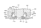
- FIG. 5 is a cross-sectional explanatory view showing a case where the intermediate member 10 is attached to the fabric 2 as a male snap 40.
- Reference numeral 60 in FIG. 5 is a male upper die that is raised and lowered by the snap attachment device.
- the male upper die 60 is similar to the punch 51 described above, and includes a punch 61 including a recessed portion 61b and the like, and a male die body 62 that surrounds the punch 61 and processes the intermediate member 10 into the male snap 40.
- the male die main body 62 includes a concave portion 62a that is recessed upward from the bottom surface thereof and that receives the peripheral side portion 12 of the intermediate member 10.
- the recess 62a has an upper end surface 62d as its bottom surface and an inner peripheral surface.
- the inner peripheral surface has an inclined portion 62b whose inner diameter gradually decreases slightly from the lower end to the upper portion, and a recess from the upper end of the inclined portion 62b.
- a small-diameter portion 62c having a substantially constant inner diameter is formed near the upper end of 62a.
- the small diameter portion 62c and the upper end surface 62d are rounded.
- the inner diameter in the vicinity of the lower end of the inclined portion 62b is substantially equal to the maximum outer diameter of the upper end portion 12b of the peripheral side portion 12 of the intermediate member 10 (the outer diameter of the outer end in the radial direction of the upper end portion 12b), and the inner diameter of the small diameter portion 62c.
- the attachment member 20 is placed on a lower die (not shown) of the press machine, and the intermediate member 10 is held by the male upper die 60.
- the holding of the intermediate member 10 with respect to the male upper die 60 is performed so that the upper end portion 12 b of the peripheral side portion 12 of the intermediate member 10 is adapted to the inclined portion 62 b of the concave portion 62 a of the male die main body 62.
- the snap attachment device is operated to lower the male upper die 60 toward the lower die.
- the post 22 of the mounting member 20 penetrates the cloth 2 upward, and then passes through the opening 13 of the bottom 11 of the intermediate member 10, and is then crimped by the recess 61 b of the punch 61 of the male upper die 60 ( Thereby, the intermediate member 10, that is, the male snap 40 is fixed to the fabric 2. At the same time, as will be described in detail below, the intermediate member 10 is processed into the male snap 40.
- the peripheral side portion 12 of the intermediate member 10 enters deeply into the concave portion 62a of the male die main body 62, and accordingly, the peripheral side portion 12 of the intermediate member 10 is moved into the concave portion 62a. It is pushed radially inward from the inclined portion 62b and the small diameter portion 62c. As a result, the base portion 12a of the peripheral side portion 12 is deformed so as to be slightly inclined upward and radially inward, and the inner diameter of the upper end portion 12b is reduced (see FIG. 5), whereby the intermediate member 10 becomes the male snap 40. .
- the peripheral side portion of the intermediate member 10, the peripheral side portion of the male snap 40 corresponding to the base portion 12a and the upper end portion 12b, the base portion and the upper end portion thereof are represented by reference numerals 42, 42a and 42b, respectively. Other parts are substantially the same as the intermediate member 10, and therefore the same reference numerals as those of the intermediate member 10 are used.
- a constricted portion 42 d having a reduced diameter is formed at the boundary between the base portion 42 a and the upper end portion 42 b in the peripheral side portion 42 of the male snap 40. The radially inward contraction from the peripheral side portion 12 to the peripheral side portion 42 is easily performed by the presence of the notch portion 14.
- the convex portion 11 a of the bottom portion 11 plays a role of tightening the fabric 1 with the base portion 21 of the attachment member 20.
- the fixing of the male snap 40 to the cloth 1 and the processing of the intermediate member 10 to the male snap 40 are the same timing as described above, and the male upper die 60 is lowered.
- the punch 61 first descends, the post portion 22 of the mounting member 20 is caulked, and then, the male die body 62 deforms the peripheral side portion 12 of the intermediate member 10 to become the male snap 40.
- the processing includes such timing processing.
- FIG. 6 is a cross-sectional explanatory view showing a state in which the female snap 30 attached to the fabric 1 and the male snap 40 attached to the fabric 2 face each other concentrically.
- FIG. 7 is an explanatory cross-sectional view showing a state in which the female snap 30 and the male snap 40 are connected from the state of FIG.
- the female snap 30 and the male snap 40 are connected by fitting the peripheral side portion 42 of the male snap 40 into a space inside the peripheral side portion 32 of the female snap 30 in the radial direction (hereinafter referred to as “female side space”).
- the connection is released by removing the peripheral side portion 42 of the male snap 40 from the female side space.
- the inner diameter (minimum inner diameter of upper end portion 32 b) of radial inner end 32 c of upper end portion 32 b of peripheral side portion 32 of female snap 30 is the upper end portion 42 b of peripheral side portion 42 of male snap 40. It is slightly smaller than the outer diameter of the radially outer end 42c (the maximum outer diameter of the upper end portion 42b). Therefore, the upper end portion 42b of the peripheral side portion 42 of the male snap 40 enters the female side space of the female snap 30 at the time of transition from the non-connected state of FIG.
- the upper end portion 42b abuts on the upper end portion 32b of the peripheral side portion 32, and the upper end portion 42b is temporarily elastically displaced radially inward and / or the upper end portion 32b temporarily outward in the radial direction.
- the elastic displacement is restored and the male snap 40 and the female snap 30 are connected (see FIG. 7).
- the upper end portion 32 a of the female snap 30 is engaged with the constricted portion 42 d of the male snap 40.
- the upper end portion 32a (and the engagement space) of the female snap 30 is a female side engaging portion, and the upper end portion 42b and the constricted portion 42d of the male snap 40 are male side engaging portions.
- FIG. 8 is a plan view showing an intermediate member 70 which is the second embodiment of the intermediate snap member of the present invention
- FIG. 9 is a cross-sectional view taken along the line BB of FIG.
- the intermediate member 70 is formed from a metal plate by drawing or the like, and includes a disk-shaped bottom portion 71, and a cylindrical peripheral side portion 72 that rises upward (upper and lower are based on FIG. 9) from the radially outer end of the bottom portion 71. Is provided.
- the bottom 71 is the same as the bottom 11 of the intermediate member 10 of the first embodiment, and includes a central opening 73 and an annular convex 71a.
- the circumferential side portion 72 is provided with six triangular cutout portions 74 at regular angular intervals (60 degrees) in the circumferential direction downward from the upper end thereof.
- the peripheral side portion 72 extends from the bottom 71 to the bottom 71 substantially perpendicularly (substantially parallel to the axis of the intermediate member 70).
- the upper end portion 12b of the peripheral side portion 12 is curled before being attached to the fabrics 1 and 2, that is, before being processed into the female snap 30 or the male snap 40.
- the peripheral side portion 72 of the member 70 has an upper end 82a or a middle portion 70 when the intermediate member 70 is attached to the fabrics 3 and 4 as male snaps 80 or female snaps 90 (see FIGS. 12 and 13, etc.). Processing to the peripheral side portion 82 or 92 including the curling of 92a is performed.
- FIG. 10 is an explanatory cross-sectional view showing a state in which the intermediate member 70 and the attachment member 20 (the same reference numerals are assigned to the intermediate member 70 and the attachment member 20 in FIG. 3) with the cloth 3 interposed therebetween. .
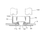
- the intermediate member 70 is lowered by operating a snap attachment device (not shown) from this state, after the post portion 22 of the attachment member 20 passes through the cloth 1 and then passes through the opening 73 of the bottom portion 71 of the intermediate member 70. 4 and a punch (not shown) similar to the punch 51 of FIG. Thereby, as shown in FIG. 11, the intermediate member 70 is fixed to the fabric 2.
- the peripheral side portion 72 of the intermediate member 70 is rotated around the male snap 80 shown in FIG. 12 by the male die body 102 of the male upper die schematically shown in FIG. In FIG. 11, for convenience, the peripheral side portion 72 of the intermediate member 70 is shown in an unprocessed state while the post portion 72 is crimped.
- the male die main body 102 includes a cylindrical portion that surrounds a punch (not shown), and has an annular recess 102a that is recessed in a substantially semicircular shape upward from its bottom surface.
- the radially outer end of the recess 102 a is at substantially the same radial position as the radially outer end of the upper end portion of the peripheral side portion 72 of the intermediate member 70.
- the intermediate member 70 becomes the male snap 80
- the peripheral side portion 72 of the intermediate member 70 becomes the peripheral side portion 82 including the curved upper end portion 82 a of the male snap 80.
- the peripheral side portion 82 of the male snap 80 includes a constricted portion 82b that protrudes slightly inward in the radial direction at a substantially middle portion in the vertical direction.
- the inner diameter of the peripheral side portion 82 excluding the curved upper end portion 82a is the smallest at the constricted portion 82b, gradually increases slightly from the constricted portion 82b to the upper upper end portion 82a, and further, the bottom portion 71 below the constricted portion 82b. It expands only slightly.
- the same reference numerals are used for the male snap 80 for the bottom 71 including the opening 73 and the convex portion 71 a of the intermediate member 70 and the cutout 74.
- the processing from the peripheral side portion 72 to the peripheral side portion 82 including the curvature of the upper end portion 82 a is easily performed by the presence of the notch portion 74.
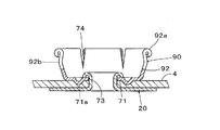
- FIG. 13 is an explanatory cross-sectional view showing a state in which the female snap 90 is formed from the intermediate member 70.
- the female snap 90 is formed by applying a female die body (not shown) to the intermediate member 70.
- the female die body has a recess (not shown) similar to the recess 102a of the male die body 102, but the inner radius end of this recess is different from that of the recess 102a.
- the intermediate member 70 is fixed to the dough 4 by the attachment member 20 by lowering the female upper die including the female die body and the punch.
- the upper end portion of the peripheral side portion 72 of the intermediate member 70 is curled in a C shape radially outward by the depression of the female die main body, and the peripheral side portion 72 is pushed downward by the female die main body.
- the intermediate portion 72 in the vertical direction of the peripheral side portion 72 (the portion slightly above the middle) is deformed so as to slightly protrude outward in the radial direction (see FIG. 13).
- the intermediate member 70 becomes the female snap 90
- the peripheral side portion 72 of the intermediate member 70 becomes the peripheral side portion 92 including the curved upper end portion 92 a of the female snap 90.
- the peripheral side portion 92 of the female snap 90 includes a protruding portion 92b that protrudes slightly outward in the radial direction at a portion slightly above the middle in the vertical direction.
- the outer diameter of the peripheral side portion 92 excluding the curved upper end portion 92a is the largest at the protruding portion 92b, gradually decreases slightly from the protruding portion 92b to the upper upper end portion 92a, and further, the bottom portion below the protruding portion 92b. It also reduces to 71.
- the same reference numerals are also used for the female snap 90 for the bottom portion 71 including the opening 73 and the convex portion 71a of the intermediate member 70, and the cutout portion 74. The processing from the peripheral side portion 72 to the peripheral side portion 92 including the curling of the upper end portion 92 a is easily performed by the presence of the notch portion 74.
- FIG. 14 is a cross-sectional explanatory view showing a state in which the male snap 80 attached to the fabric 3 and the female snap 90 attached to the fabric 4 are concentrically opposed to each other.
- FIG. 15 is a cross-sectional explanatory view showing a state in which the male snap 80 and the female snap 90 are connected from the state of FIG.
- the male snap 80 and the female snap 90 are connected by fitting the peripheral side portion 82 of the male snap 80 into the female side space radially inward of the peripheral side portion 92 of the female snap 90, and this connection is released. This is done by extracting the peripheral side portion 82 of the male snap 80 from the female side space. Referring to FIG.
- the inner diameter (minimum inner diameter of upper end portion 92 a) of radial inner end 92 c of upper end portion 92 a of peripheral side portion 92 of female snap 90 is the upper end portion 82 a of peripheral side portion 82 of male snap 80. It is slightly smaller than the outer diameter of the radially outer end 82c (the maximum outer diameter of the upper end 82a). Therefore, at the time of transition from the unconnected state of FIG. 14 to the connected state of FIG. 15, the upper end portion 82 a of the peripheral side portion 82 of the male snap 80 immediately before entering the female side space of the female snap 90.
- the upper end portion 82a abuts on the upper end portion 82a of the circumferential side portion 82, and the upper end portion 82a is temporarily elastically displaced radially inward and / or the upper end portion 92a temporarily outward in the radial direction. Then, when the upper end portion 82a on the male snap 80 side gets over the upper end portion 92a on the female snap 90 side, the elastic displacement is restored, and the radially outer end 82c of the upper end portion 82a of the peripheral side portion 82 of the male snap 80 is restored.
- the male snap 80 and the female snap 90 are connected (see FIG. 15).
- the upper end portion 82a and the constricted portion 82b of the male snap 80 are male side engaging portions
- the upper end portion 92a and the protruding portion 92b (and the engaging space) of the female snap 90 are female side engaging portions.
- the male snap 80 and the female snap 90 are formed from the same intermediate member 10, and the diameter of the bottom 11, the diameter of the opening 13, the position where the protrusion 11 a is formed, and the notch 14. Can be recognized as the same intermediate member 10.
- the diameter of the bottom and the number of notches are the same, so that it can be recognized as the same intermediate member. Furthermore, by measuring the dimensions of the peripheral side portion 12 and comparing the dimensions of both peripheral side portions 12, it is possible to analyze and judge more accurately.
- FIG. 16 is an explanatory cross-sectional view showing another example of the attachment member.
- the mounting member 110 includes a disk-shaped base portion 111 and pins 112 (shown by being crimped in a curved shape in FIG. 16) that protrude from the base portion 111.
- the base 111 includes a disk-shaped core 111a that is integral with the pin 112, and a metal cover 111b that covers the core 111a.
- the pin 112 and the core 111a are made of metal or synthetic resin.
- the intermediate member 70a shown in a state where it is not processed into a male snap or a female snap is the same as the intermediate member 70 described above except that an opening is not provided at the center of the bottom portion 71b. is there.
- each pin 112 penetrates the fabric 3a upward, and then penetrates the bottom 71b of the intermediate member 70a, and then is curved by an upper die (not shown). Clamped on. Thereby, the intermediate member 70a is fixed to the cloth 3a.
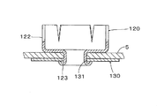
- FIG. 17 is an explanatory cross-sectional view showing a state in which the intermediate member 120, which is the third embodiment of the intermediate snap member of the present invention, and the washer 130 are arranged concentrically with the fabric 5 interposed therebetween.
- FIG. 18 is a cross-sectional explanatory view showing a state in which the intermediate member 120 is attached to the fabric 5.
- the intermediate member 120 is formed from a metal plate by drawing or the like, and includes a disk-shaped bottom 121, a cylindrical peripheral side portion 122 that rises upward from the radially outer end of the bottom 121, and a lower portion from the center of the bottom 121. And a protruding cylindrical post portion 123.
- the circumferential side portion 122 is the same as the circumferential side portion 72 of the intermediate member 70 of the second embodiment, and has six notches 124 in the circumferential direction.
- the post portion 123 is concentric with the axis of the intermediate member 120 and has a substantially constant diameter. Further, the lower end side of the post portion 123 is opened, and the upper end side is also opened to a space inside the circumferential side portion 122 in the radial direction.
- the washer 130 is a disk-shaped metal member having an opening 131 having substantially the same diameter as the outer diameter of the post portion 123.
- the intermediate member 120 is attached to the fabric 5 as shown in FIG.
- the intermediate member 120 is processed into a male snap or a female snap at the same time as the caulking process.
- the peripheral side portion 122 of the intermediate member 120 is shown in an unprocessed state. This is to explain that the peripheral side portion 122 is deformed by the lowering of the series of female upper die or male upper die so as to be a female snap or a male snap. Expressed as simultaneous.
- FIG. 19 shows an intermediate member 70b which is a modification of the intermediate member 70 of the second embodiment described in FIGS.
- the intermediate member 70b is formed on the inner peripheral surface of the peripheral side portion 72 (substantially the same as the intermediate member 70, and therefore has the same reference number) and the constricted portion 82b of the male snap member 80 or the female snap 90 described above.
- a portion to be buckled as the protruding portion 92b has a slight groove 72b or a recess continuous in the circumferential direction.
- the intermediate member is attached to the cloth by the attachment member.
- the attachment process to the cloth on the intermediate member and the formation of the female snap or the male snap are the same for the female. It is performed by an upper die or a male upper die. Therefore, it is not preferable in terms of manufacturing cost and inventory management to perform the attachment process and the female snap or the male snap in separate steps.
- the female snap or the male snap can be selectively formed by exchanging (replacing) the female upper die or the male upper die.
- the punch for caulking the post of the mounting member is the same, it is not necessary to replace the punch.
- the punch may be incorporated in the attachment device.
Landscapes
- Slide Fasteners, Snap Fasteners, And Hook Fasteners (AREA)
Abstract
L'invention concerne un procédé de façonnage de bouton pression qui permet de réduire les coûts de production de la fixation à pression et la charge de travail due au contrôle des stocks. On obtient un élément intermédiaire de fixation (10), qui présente une partie inférieure (11) en forme de disque et une partie latérale (12) cylindrique qui se dresse sur le bord extérieur de la partie inférieure (11) dans la direction radiale. Ensuite, on déforme la partie latérale (12) de l'élément intermédiaire de fixation (10) pour constituer sélectivement et selon les souhaits un bouton pression mâle (40) ou un bouton pression femelle (30). L'élément intermédiaire de fixation (10) peut être réalisé en métal. On peut faire fonctionner l'élément intermédiaire de fixation (10) sur le bouton pression mâle (40) ou le bouton pression femelle (30) quand l'élément intermédiaire de fixation (10) est fixé à un tissu (15).
Priority Applications (3)
| Application Number | Priority Date | Filing Date | Title |
|---|---|---|---|
| JP2013526702A JP5599947B2 (ja) | 2011-08-04 | 2011-08-04 | スナップボタンの形成方法、中間スナップ部材、及びスナップボタン |
| PCT/JP2011/067884 WO2013018226A1 (fr) | 2011-08-04 | 2011-08-04 | Procédé de façonnage de bouton pression, élément intermédiaire de fixation et fixation à pression |
| CN201180072625.3A CN103717101B (zh) | 2011-08-04 | 2011-08-04 | 按扣的形成方法、按扣中间件以及按扣 |
Applications Claiming Priority (1)
| Application Number | Priority Date | Filing Date | Title |
|---|---|---|---|
| PCT/JP2011/067884 WO2013018226A1 (fr) | 2011-08-04 | 2011-08-04 | Procédé de façonnage de bouton pression, élément intermédiaire de fixation et fixation à pression |
Publications (1)
| Publication Number | Publication Date |
|---|---|
| WO2013018226A1 true WO2013018226A1 (fr) | 2013-02-07 |
Family
ID=47628786
Family Applications (1)
| Application Number | Title | Priority Date | Filing Date |
|---|---|---|---|
| PCT/JP2011/067884 Ceased WO2013018226A1 (fr) | 2011-08-04 | 2011-08-04 | Procédé de façonnage de bouton pression, élément intermédiaire de fixation et fixation à pression |
Country Status (3)
| Country | Link |
|---|---|
| JP (1) | JP5599947B2 (fr) |
| CN (1) | CN103717101B (fr) |
| WO (1) | WO2013018226A1 (fr) |
Cited By (2)
| Publication number | Priority date | Publication date | Assignee | Title |
|---|---|---|---|---|
| JPWO2024162394A1 (fr) * | 2023-02-01 | 2024-08-08 | ||
| WO2025004363A1 (fr) * | 2023-06-30 | 2025-01-02 | Ykk株式会社 | Bouton-pression femelle |
Families Citing this family (6)
| Publication number | Priority date | Publication date | Assignee | Title |
|---|---|---|---|---|
| CN105077858B (zh) * | 2015-07-31 | 2018-07-27 | 浙江伟星实业发展股份有限公司 | 一种组合拍扣及其制作方法 |
| US10897965B2 (en) * | 2016-03-30 | 2021-01-26 | Ykk Corporation | Snap button and male body forming method |
| US11528967B2 (en) | 2018-11-22 | 2022-12-20 | Ykk Corporation | Male snap button and female snap button |
| CN110353362B (zh) * | 2019-08-13 | 2025-11-07 | 石狮市龙翔五金塑料制品有限公司 | 一种简约型母扣 |
| CN110638153B (zh) * | 2019-08-30 | 2022-06-03 | 宏基钮扣(石狮)有限公司 | 一种高精度钮扣 |
| JP7719068B2 (ja) * | 2020-06-19 | 2025-08-05 | Ykk株式会社 | ソケット |
Citations (2)
| Publication number | Priority date | Publication date | Assignee | Title |
|---|---|---|---|---|
| JP2006068388A (ja) * | 2004-09-03 | 2006-03-16 | Ykk Corp | 止め具およびボタン |
| WO2009107782A1 (fr) * | 2008-02-29 | 2009-09-03 | Ykk株式会社 | Partie d'encliquetage mâle et partie d'encliquetage femelle |
Family Cites Families (3)
| Publication number | Priority date | Publication date | Assignee | Title |
|---|---|---|---|---|
| JPH1132815A (ja) * | 1997-07-17 | 1999-02-09 | Ykk Corp | スナップボタンおよびその取付方法 |
| JP3100361B2 (ja) * | 1997-12-29 | 2000-10-16 | スコービル・ジャパン株式会社 | 釦 |
| JP4034281B2 (ja) * | 2004-03-26 | 2008-01-16 | 丸山金属工業株式会社 | ホック・ハトメ金具及びワッシャ |
-
2011
- 2011-08-04 CN CN201180072625.3A patent/CN103717101B/zh active Active
- 2011-08-04 WO PCT/JP2011/067884 patent/WO2013018226A1/fr not_active Ceased
- 2011-08-04 JP JP2013526702A patent/JP5599947B2/ja active Active
Patent Citations (2)
| Publication number | Priority date | Publication date | Assignee | Title |
|---|---|---|---|---|
| JP2006068388A (ja) * | 2004-09-03 | 2006-03-16 | Ykk Corp | 止め具およびボタン |
| WO2009107782A1 (fr) * | 2008-02-29 | 2009-09-03 | Ykk株式会社 | Partie d'encliquetage mâle et partie d'encliquetage femelle |
Cited By (4)
| Publication number | Priority date | Publication date | Assignee | Title |
|---|---|---|---|---|
| JPWO2024162394A1 (fr) * | 2023-02-01 | 2024-08-08 | ||
| WO2024162394A1 (fr) * | 2023-02-01 | 2024-08-08 | 株式会社インスピレーション・ワールド | Bouton-pression à positions de fixation variables |
| JP7682481B2 (ja) | 2023-02-01 | 2025-05-26 | 株式会社インスピレーション・ワールド | 留め位置可変スナップボタン |
| WO2025004363A1 (fr) * | 2023-06-30 | 2025-01-02 | Ykk株式会社 | Bouton-pression femelle |
Also Published As
| Publication number | Publication date |
|---|---|
| JP5599947B2 (ja) | 2014-10-01 |
| JPWO2013018226A1 (ja) | 2015-03-05 |
| CN103717101A (zh) | 2014-04-09 |
| CN103717101B (zh) | 2016-01-20 |
Similar Documents
| Publication | Publication Date | Title |
|---|---|---|
| JP5599947B2 (ja) | スナップボタンの形成方法、中間スナップ部材、及びスナップボタン | |
| EP3228206B1 (fr) | Structure supérieure de bouton-pression femelle, bouton-pression femelle et procédé de fixation de bouton-pression femelle sur un matériau | |
| US20150352622A1 (en) | Method for forming a pressed component, method for manufacturing a pressed component, and die apparatus for forming a pressed component | |
| JP2013160292A (ja) | ころ軸受保持器及びころ軸受保持器の製造方法 | |
| EP2826573B1 (fr) | Procédé de production d' un élément de retenue | |
| KR101935703B1 (ko) | 암형 스냅 버튼 | |
| KR101683647B1 (ko) | 이너레이스와 보스의 복합 단조품 분리장치 및 방법 | |
| US20120317760A1 (en) | Button Fastener, Method for Forming Button Fastener, Eyelet, and Method for Forming Eyelet | |
| US7331874B2 (en) | Method for producing circular washer | |
| JP5859030B2 (ja) | ボタン取付装置及びボタン保持ダイ | |
| KR101163742B1 (ko) | 다중반지 및 그 제작방법 | |
| KR101753096B1 (ko) | 메탈 아일릿 | |
| CN106963049B (zh) | 按扣和雄体形成方法 | |
| TWI501735B (zh) | Pressing method and buckle | |
| US3310871A (en) | Method of collapsing stud breast | |
| JP6578488B1 (ja) | 打ち抜き装置 | |
| KR101747380B1 (ko) | 대형 소쿠리 제조방법 | |
| US11305325B2 (en) | Processing method for metal plate | |
| JP6252806B2 (ja) | ロックパウルの製造方法及び非対称部品の製造方法 | |
| KR101596349B1 (ko) | 자동 변속기용 클러치 리액션 플레이트의 제조방법과 그 제조방법으로 제작된 클러치 리액션 플레이트 | |
| JP2007244667A (ja) | 飾りボタン | |
| CN108266494B (zh) | 无级变速器的传动带的横向段的制造方法及制造的横向段 | |
| JP3206924U (ja) | 取付台座および宝飾体 | |
| JP2014151359A (ja) | 環状部材の製造方法 | |
| JP2018518204A (ja) | 伸張性バングルブレスレッド |
Legal Events
| Date | Code | Title | Description |
|---|---|---|---|
| 121 | Ep: the epo has been informed by wipo that ep was designated in this application |
Ref document number: 11870216 Country of ref document: EP Kind code of ref document: A1 |
|
| ENP | Entry into the national phase |
Ref document number: 2013526702 Country of ref document: JP Kind code of ref document: A |
|
| NENP | Non-entry into the national phase |
Ref country code: DE |
|
| 122 | Ep: pct application non-entry in european phase |
Ref document number: 11870216 Country of ref document: EP Kind code of ref document: A1 |