WO2013018231A1 - 携帯用電子機器 - Google Patents
携帯用電子機器 Download PDFInfo
- Publication number
- WO2013018231A1 WO2013018231A1 PCT/JP2011/067904 JP2011067904W WO2013018231A1 WO 2013018231 A1 WO2013018231 A1 WO 2013018231A1 JP 2011067904 W JP2011067904 W JP 2011067904W WO 2013018231 A1 WO2013018231 A1 WO 2013018231A1
- Authority
- WO
- WIPO (PCT)
- Prior art keywords
- electronic device
- corner
- groove
- frame
- portable electronic
- Prior art date
- Legal status (The legal status is an assumption and is not a legal conclusion. Google has not performed a legal analysis and makes no representation as to the accuracy of the status listed.)
- Ceased
Links
Images



Classifications
-
- H—ELECTRICITY
- H05—ELECTRIC TECHNIQUES NOT OTHERWISE PROVIDED FOR
- H05K—PRINTED CIRCUITS; CASINGS OR CONSTRUCTIONAL DETAILS OF ELECTRIC APPARATUS; MANUFACTURE OF ASSEMBLAGES OF ELECTRICAL COMPONENTS
- H05K5/00—Casings, cabinets or drawers for electric apparatus
- H05K5/06—Hermetically-sealed casings
- H05K5/061—Hermetically-sealed casings sealed by a gasket held between a removable cover and a body, e.g. O-ring, packing
-
- G—PHYSICS
- G06—COMPUTING OR CALCULATING; COUNTING
- G06F—ELECTRIC DIGITAL DATA PROCESSING
- G06F1/00—Details not covered by groups G06F3/00 - G06F13/00 and G06F21/00
- G06F1/16—Constructional details or arrangements
- G06F1/1613—Constructional details or arrangements for portable computers
- G06F1/1633—Constructional details or arrangements of portable computers not specific to the type of enclosures covered by groups G06F1/1615 - G06F1/1626
- G06F1/1656—Details related to functional adaptations of the enclosure, e.g. to provide protection against EMI, shock, water, or to host detachable peripherals like a mouse or removable expansions units like PCMCIA cards, or to provide access to internal components for maintenance or to removable storage supports like CDs or DVDs, or to mechanically mount accessories
-
- H—ELECTRICITY
- H04—ELECTRIC COMMUNICATION TECHNIQUE
- H04M—TELEPHONIC COMMUNICATION
- H04M1/00—Substation equipment, e.g. for use by subscribers
- H04M1/02—Constructional features of telephone sets
- H04M1/0202—Portable telephone sets, e.g. cordless phones, mobile phones or bar type handsets
- H04M1/026—Details of the structure or mounting of specific components
- H04M1/0262—Details of the structure or mounting of specific components for a battery compartment
-
- H—ELECTRICITY
- H04—ELECTRIC COMMUNICATION TECHNIQUE
- H04M—TELEPHONIC COMMUNICATION
- H04M1/00—Substation equipment, e.g. for use by subscribers
- H04M1/02—Constructional features of telephone sets
- H04M1/18—Telephone sets specially adapted for use in ships, mines, or other places exposed to adverse environment
Definitions
- This invention relates to a portable electronic device.
- the O-ring becomes hard at the corner where the cross-sectional area of the concave groove is narrower than the side, and the elasticity of the O-ring is lost. There is a problem that the waterproofness is inferior.
- An object of the present invention is to provide a portable electronic device that can improve the waterproof performance at the corner of the O-ring.
- the portable electronic device has a waterproof structure that covers the surface of the opening provided in the housing with a lid.
- a portable electronic device includes an attachment portion formed on one of a housing and a lid.
- a frame-shaped packing (O-ring) surrounding the periphery of the opening is attached to the outer peripheral surface of the attachment portion.
- the attachment portion has a side portion and a corner portion and has a shape surrounding the periphery of the opening.
- the portable electronic device includes a groove portion formed on the outer peripheral surface of the attachment portion.
- a frame-shaped packing is accommodated in the groove portion so that the surface of the frame-shaped packing can be pressed against the other of the housing and the lid.
- the shape at the corner of the groove is different from the shape at the side.
- the waterproof performance at the corner of the frame packing can be improved.
- FIG. 1 is an exploded perspective view illustrating a portable electronic device according to an embodiment.
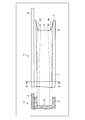
- 2A and 2B are a side view and a cross-sectional view showing a mounting portion and a groove portion of the portable electronic device according to the embodiment.
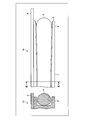
- 3A and 3B are a side view and a cross-sectional view showing a mounting portion and a frame packing of the portable electronic device according to the example.
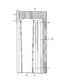
- FIG. 4 is a side sectional view showing a waterproof structure of the portable electronic device according to the example.
- FIG. 5: is sectional drawing which shows the waterproof structure in the side part of the attachment part of the portable electronic device concerning an Example.
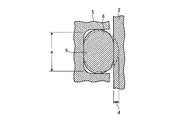
- FIG. 6 is a cross-sectional view illustrating a waterproof structure in a corner portion of the mounting portion of the portable electronic device according to the example.
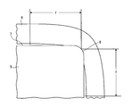
- FIG. 7 is a diagram for explaining an example of the dimension of the groove of the portable electronic device according to the example.
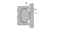
- FIG. 8 is a cross-sectional view showing the frame packing at the corner when the shape of the corner of the groove is the same as the shape of the side.
- FIG. 9 is a cross-sectional view showing the waterproof structure at the corner when the shape of the corner of the groove is the same as the shape of the side.
- FIG. 1 is an exploded perspective view illustrating a portable electronic device according to an embodiment.
- the portable electronic device 1 has a waterproof structure that covers the surface of the opening 3 provided in the housing 2 with a lid 4.
- An attachment portion 5 is formed on one of the housing 2 and the lid 4.
- description will be made assuming that the attachment portion 5 is formed on the lid body 4.
- a frame-shaped packing (O-ring) 6 surrounding the periphery of the opening 3 is attached to the outer peripheral surface of the attachment portion 5.
- the attachment portion 5 has side portions 7 and corner portions 8.
- the attachment portion 5 has a shape surrounding the opening 3.
- FIG. 2 is a side view and a cross-sectional view showing a mounting portion and a groove portion of the portable electronic device according to the embodiment.
- the right side view indicated by reference numeral 11 is a side view including the corner portion 8 of the attachment portion 5, and the left side view indicated by reference number 12 is taken along the cutting line II-II of the side portion 7 of the attachment portion 5. It is sectional drawing.
- a groove portion 9 is formed on the outer peripheral surface of the attachment portion 5. The shape at the corner 8 of the groove 9 is different from the shape at the side 7.
- FIG. 3 is a side view and a cross-sectional view showing a mounting portion and a frame packing of the portable electronic device according to the embodiment.
- the right-side view indicated by reference numeral 14 is a side view including the corner portion 8 of the attachment portion 5
- the left-side view indicated by reference numeral 15 is a cut line III-III of the side portion 7 of the attachment portion 5. It is sectional drawing.
- the frame-shaped packing 6 is accommodated in the groove 9 so that the surface of the frame-shaped packing 6 can be pressed against the housing 2.
- the attachment portion 5 is formed in the housing 2
- the frame-shaped packing 6 is accommodated in the groove portion 9 so that the surface of the frame-shaped packing 6 can be pressed against the lid body 4.
- FIG. 4 is a side sectional view showing a waterproof structure of the portable electronic device according to the example.
- the surface portion of the frame-shaped packing 6 that protrudes from the groove portion 9 at the corner portion 8 contacts the inner peripheral surface of the housing 2.
- the side portion 7, and the surface portion of the frame-shaped packing 6 protruding from the groove portion 9 is in contact with the inner peripheral surface of the housing 2.
- FIG. 5 is a cross-sectional view showing a waterproof structure in the side portion of the mounting portion of the portable electronic device according to the embodiment.
- FIG. 6 is a cross-sectional view illustrating a waterproof structure in a corner portion of the mounting portion of the portable electronic device according to the example. 5 and 6, the alternate long and short dash line indicates the shape of the frame-shaped packing 6 before contacting the inner peripheral surface of the housing 2.
- the frame packing 6 is in contact with the inner peripheral surface of the housing 2 in a state of being crushed with a sufficient crushing amount d.
- the width of the bottom of the groove 9 in the side 7 is a.
- the value of a is such that when the frame packing 6 is crushed with a sufficient crushing amount d, the frame packing 6 is crushed when it contacts the inner peripheral surface of the opening 3 of the housing 2.
- the groove 9 may be just closed.
- the width of the bottom of the groove 9 is b, and the width of the open end of the groove 9 is c.
- the relationship of [b ⁇ a ⁇ c] may be materialized.
- the depth of the groove part 9 may be the same in the side part 7 and the corner part 8, and the corner part 8 may be shallower.
- the frame packing 6 is in contact with the inner peripheral surface of the opening 3 of the housing 2 in a state of being crushed with a sufficient crushing amount e.
- the shape of the groove portion 9 at the corner portion 8 is different from the shape at the side portion 7, and the frame-shaped packing 6 does not become hard at the corner portion 8 of the groove portion 9, and the opening 3 of the housing 2. Since it contacts the inner peripheral surface, the waterproof performance at the corners of the frame packing 6 can be improved.
- Example 2 In the second embodiment, for example, the waterproof structure described in the first embodiment is applied to a mobile phone.
- the waterproof structure described in Embodiment 1 is applicable not only to mobile phones but also to various portable electronic devices such as portable game machines and portable electronic dictionaries.
- the battery 10 may be accommodated in the opening 3 of the housing 2.
- the width of the bottom of the groove 9 is a at the side 7, b at the corner 8 (b ⁇ a), and gradually decreases from the side 7 to the corner 8. May be.
- “in stages” may include “gradually”.
- the portion sandwiched between the two-dot chain line 21 and the two-dot chain line 22 is approximately the bottom of the groove 9.
- the bottom surface of the groove 9 and the wall surface rising from the bottom surface may be connected by a smooth curved surface. In this case, the boundary between the bottom surface and the wall surface of the groove 9 is not clear.
- the two-dot chain lines 21 and 22 are drawn for convenience in order to clearly show that the width of the bottom of the groove portion 9 is gradually narrowed.
- the bottom width b of the groove portion 9 in the corner portion 8 may be set to the same width as the wire diameter of the frame packing 6 in the side portion 7. As a result, it is possible to suppress the frame-shaped packing 6 from being flattened at the corner portion 8 rather than extending at the side portion 7.
- the wall surface of the groove portion 9 in the side portion 7 may be perpendicular to the bottom surface. That is, in the side part 7, the wall surface of the groove part 9 does not need to incline. As shown in side views 11 and 6 on the right side of FIG. 2, in the corner portion 8, the wall surface of the groove portion 9 has an inclined surface that spreads from the bottom surface toward the opening end. In FIG. 2, the outer side of the two-dot chain line 23 and the outer part of the two-dot chain line 24 are inclined surfaces.
- the cross-sectional area of the region that accommodates the frame packing 6 in the groove portion 9 may be substantially the same in the side portion 7 and the corner portion 8. If it does so, since the filling rate of the frame-shaped packing 6 with respect to the groove part 9 becomes substantially the same in the side part 7 and the corner
- FIG. 7 is a diagram for explaining an example of the dimension of the groove portion of the portable electronic device according to the embodiment.
- FIG. 7 shows an enlarged view of the vicinity of the corner portion 8 in a state in which the frame packing 6 is attached to the attachment portion 5.
- the attachment portion 5 does not have the groove portion 9.
- the frame-shaped packing 6 has more elongation at the corners 8 than at the side parts 7.
- the cross-sectional area of the frame packing 6 changes from the side 7 toward the corner 8.
- the present inventors investigated it became clear that the cross-sectional area of the frame-shaped packing 6 changed in the range of about 3 mm from the center of the corner
- the corner portion within a range in which the shape of the groove portion 9 is changed from the side portion 7 to the corner portion 8.
- the distance f from the center of 8 is preferably 2 mm or more and 5 mm or less. That is, the shape of the groove portion 9 may be changed stepwise from a location 5 mm away from the center of the corner portion 8 toward the center of the corner portion 8. In addition, it is preferable to change the shape of the groove portion 9 stepwise from a location 2 mm away from the center of the corner portion 8 toward the center of the corner portion 8 at a minimum. Further, the shape of the groove 9 may be changed stepwise from a position 3 mm away from the center of the corner 8 toward the center of the corner 8.
- FIG. 8 is a cross-sectional view showing a frame-like packing at a corner when the shape of the corner of the groove is the same as the shape of the side.
- FIG. 9 is a cross-sectional view showing the waterproof structure at the corner when the shape of the corner of the groove is the same as the shape of the side.
- the frame-shaped packing 31 extends in the corner portion in the groove portion 33 of the attachment portion 32 than in the side portion. Flattened. Therefore, as shown in FIG. 9, at the corner, the surface of the frame-shaped packing 31 does not contact the inner peripheral surface of the opening of the housing, or even if it contacts, it does not contact with a sufficient amount of crushing. Therefore, sufficient waterproof performance cannot be obtained at the corners.
- the curvature (radius) of the corner is, for example, about twice the wire diameter of the frame packing. It was found that the flattening of the frame-like packing at the corners was suppressed, and waterproof performance was obtained at the corners. Therefore, the curvature (radius) of the corner may be set to about twice the wire diameter of the frame packing. In this case, since the curvature (radius) of the four corners of the opening 3 of the housing 2 is about twice the wire diameter of the frame packing, for example, the opening 3 of the housing 2 is larger than the battery 10. Accordingly, the attachment portion 5 of the lid 4 becomes large.
- the curvature (radius) of the corner portion is set to 0.5 mm, for example, by changing the shape of the groove portion 9 stepwise from the side portion 7 to the corner portion 8 as in the second embodiment.
- the curvature (radius) of the corner may be set to about 0.5 mm.
- the curvature (radius) of the four corners of the opening 3 of the housing 2 is about 0.5 mm
- the size of the opening 3 of the housing 2 and the attachment portion 5 of the lid 4 is, for example, the battery 10. Since it can be made the same degree, the portable electronic device 1 can be reduced in size.
- the same effect as the first embodiment can be obtained. Further, since the frame packing 6 does not have to be hard at the corner 8 of the groove 9, it is possible to prevent an excessive reaction force from being applied to the housing 2 against which the frame packing 6 is pressed. Accordingly, it is not necessary to increase the wall thickness of the housing 2 and make the housing 2 robust, so that the portable electronic device 1 can be reduced in size and weight.
Landscapes
- Engineering & Computer Science (AREA)
- Computer Hardware Design (AREA)
- General Engineering & Computer Science (AREA)
- Theoretical Computer Science (AREA)
- Human Computer Interaction (AREA)
- Physics & Mathematics (AREA)
- General Physics & Mathematics (AREA)
- Signal Processing (AREA)
- Microelectronics & Electronic Packaging (AREA)
- Telephone Set Structure (AREA)
- Casings For Electric Apparatus (AREA)
Abstract
携帯用電子機器(1)は、筐体(2)に設けられた開口部(3)の表面を蓋体(4)で覆う防水構造を有する。携帯用電子機器(1)は、筐体(2)及び蓋体(4)の何れか一方に形成された取付部(5)を備える。取付部(5)の外周面には、開口部(3)の周囲を取り囲む枠状パッキン(Oリング)(6)が取り付けられる。取付部(5)は、辺部(7)と角部(8)とを有して開口部(3)の周囲を取り囲む形状である。携帯用電子機器(1)は、取付部(5)の外周面上に形成された溝部(9)を備える。溝部(9)には枠状パッキン(6)が、筐体(2)及び蓋体(4)の他方に枠状パッキン(6)の表面を圧接可能に収容される。溝部(9)の角部(8)における形状は、辺部(7)における形状と異なっている。
Description
この発明は、携帯用電子機器に関する。
従来、電子機器などの防水構造において、Oリングが圧入される矩形枠状の凹溝の角部での断面積を、Oリングが圧入される際の変形に合わせて、他の部分、すなわち辺部よりも狭くなるようにした構造がある(例えば、特許文献1参照)。また、液状のパッキン材が注入される溝の角部の溝幅を辺部よりも広げて容量を増加させるようにした防水構造がある(例えば、特許文献2参照)。
しかしながら、従来のOリングを用いた防水構造では、凹溝の断面積が辺部よりも狭い角部においてOリングが硬くなり、Oリングの弾力性が失われてしまうため、Oリングの角部で防水性が劣るという問題点がある。
Oリングの角部での防水性能を改善することができる携帯用電子機器を提供することを目的とする。
携帯用電子機器は、筐体に設けられた開口部の表面を蓋体で覆う防水構造を有する。携帯用電子機器は、筐体及び蓋体の何れか一方に形成された取付部を備える。取付部の外周面には、開口部の周囲を取り囲む枠状パッキン(Oリング)が取り付けられる。取付部は、辺部と角部とを有して開口部の周囲を取り囲む形状である。携帯用電子機器は、取付部の外周面上に形成された溝部を備える。溝部には枠状パッキンが、筐体及び蓋体の他方に枠状パッキンの表面を圧接可能に収容される。溝部の角部における形状は、辺部における形状と異なっている。
この携帯用電子機器によれば、枠状パッキンの角部での防水性能を改善することができる。
以下に、この発明にかかる携帯用電子機器の実施例を図面に基づいて詳細に説明する。なお、この実施例によりこの発明が限定されるものではない。
(実施例1)
図1は、実施例にかかる携帯用電子機器を示す分解斜視図である。図1に示すように、携帯用電子機器1は、筐体2に設けられた開口部3の表面を蓋体4で覆う防水構造を有している。筐体2及び蓋体4の何れか一方には、取付部5が形成されている。ここでは、取付部5が蓋体4に形成されているものとして説明する。
図1は、実施例にかかる携帯用電子機器を示す分解斜視図である。図1に示すように、携帯用電子機器1は、筐体2に設けられた開口部3の表面を蓋体4で覆う防水構造を有している。筐体2及び蓋体4の何れか一方には、取付部5が形成されている。ここでは、取付部5が蓋体4に形成されているものとして説明する。
取付部5の外周面には、開口部3の周囲を取り囲む枠状パッキン(Oリング)6が取り付けられている。取付部5は、辺部7と角部8とを有している。取付部5は、開口部3の周囲を取り囲む形状をしている。
図2は、実施例にかかる携帯用電子機器の取付部及び溝部を示す側面図及び断面図である。図2において、符号11で示す右側の図は、取付部5の角部8を含む側面図であり、符号12で示す左側の図は、取付部5の辺部7の切断線II-IIにおける断面図である。図2に示すように、取付部5の外周面上には、溝部9が形成されている。溝部9の角部8における形状は、辺部7における形状と異なっている。
図3は、実施例にかかる携帯用電子機器の取付部及び枠状パッキンを示す側面図及び断面図である。図3において、符号14で示す右側の図は、取付部5の角部8を含む側面図であり、符号15で示す左側の図は、取付部5の辺部7の切断線III-IIIにおける断面図である。図3に示すように、溝部9には枠状パッキン6が、筐体2に枠状パッキン6の表面を圧接可能に収容されている。取付部5が筐体2に形成されている場合には、枠状パッキン6は、溝部9に、蓋体4に枠状パッキン6の表面を圧接可能に収容される。
図4は、実施例にかかる携帯用電子機器の防水構造を示す側面断面図である。図4に示すように、角部8において溝部9から突出した枠状パッキン6の表面部分が、筐体2の内周面に接する。辺部7においても同様であり、溝部9から突出した枠状パッキン6の表面部分が筐体2の内周面に接する。
図5は、実施例にかかる携帯用電子機器の取付部の辺部における防水構造を示す断面図である。図6は、実施例にかかる携帯用電子機器の取付部の角部における防水構造を示す断面図である。図5及び図6において、一点鎖線は、筐体2の内周面に接する前の枠状パッキン6の形状を示す。
図5に示すように、辺部7においては、枠状パッキン6は、十分な潰し量dで潰れた状態で筐体2の内周面に接する。辺部7における溝部9の底の幅をaとする。aの値は、図5に示すように、十分な潰し量dで枠状パッキン6が潰れた状態で筐体2の開口部3の内周面に接したときに、潰れた枠状パッキン6によって溝部9が丁度塞がれる程度であってもよい。
図6に示すように、角部8において、溝部9の底の幅をbとし、溝部9の開口端の幅をcとする。aとbとcとの間には、特に限定しないが、例えば[b<a<c]の関係が成り立っていてもよい。また、溝部9の深さは、辺部7と角部8とで同じであってもよいし、角部8の方が浅くなっていてもよい。図6に示すように、枠状パッキン6は、十分な潰し量eで潰れた状態で筐体2の開口部3の内周面に接する。
実施例1によれば、溝部9の角部8における形状が辺部7における形状と異なっており、溝部9の角部8において枠状パッキン6が硬くならずに筐体2の開口部3の内周面に接するので、枠状パッキン6の角部での防水性能を改善することができる。
(実施例2)
実施例2は、例えば携帯電話機に実施例1で説明した防水構造を適用したものである。なお、実施例1で説明した防水構造は、携帯電話機に限らず、携帯型のゲーム機や携帯型の電子辞書など、種々の携帯用電子機器に適用可能である。図1及び図4に示すように、例えば筐体2の開口部3には、電池10が収容されてもよい。
実施例2は、例えば携帯電話機に実施例1で説明した防水構造を適用したものである。なお、実施例1で説明した防水構造は、携帯電話機に限らず、携帯型のゲーム機や携帯型の電子辞書など、種々の携帯用電子機器に適用可能である。図1及び図4に示すように、例えば筐体2の開口部3には、電池10が収容されてもよい。
図2に示すように、溝部9の底の幅は、辺部7においてaであり、角部8においてb(b<a)であり、辺部7から角部8にかけて段階的に狭くなっていてもよい。ここで、「段階的に」には、「徐々に」も含まれていてもよい。図2では、二点鎖線21と二点鎖線22とで挟まれる部分がおよそ溝部9の底である。なお、厳密には、溝部9の底面と、底面から起ち上がる壁面とが滑らかな曲面で繋がっていてもよく、その場合には溝部9の底面と壁面との境は明確ではない。二点鎖線21,22は、溝部9の底の幅が徐々に狭くなっていることを明示するために、便宜上引かれたものである。
ここで、角部8における溝部9の底の幅bは、辺部7における枠状パッキン6の線径と同じ幅に設定されていてもよい。それによって、角部8において枠状パッキン6が辺部7での伸びよりも伸びて扁平化してしまうのを抑制することができる。
また、図2の左側の断面図12及び図5に示すように、辺部7では、溝部9の壁面は、底面に対して垂直であってもよい。すなわち、辺部7では、溝部9の壁面が傾斜していなくてもよい。図2の右側の側面図11及び図6に示すように、角部8では、溝部9の壁面は、底面から開口端へ向かって広がるような傾斜面を有している。図2では、二点鎖線23の外側と二点鎖線24の外側の部分が傾斜面である。溝部9の開口端の幅cと辺部7における溝部9の底の幅a及び角部8における溝部9の底の幅bとの間には、上述したように、例えば[b<a<c]の関係が成り立っていてもよい。
また、溝部9の、枠状パッキン6を収容する領域の断面積が、辺部7と角部8とで略同一であってもよい。そうすれば、辺部7と角部8とで、溝部9に対する枠状パッキン6の充填率が略同じになるので、角部8において辺部7と同程度の防水性能が得られる。
図7は、実施例にかかる携帯用電子機器の溝部の寸法の一例を説明する図である。図7には、取付部5に枠状パッキン6が取り付けられた状態の角部8付近の拡大図が示されている。なお、図7では、取付部5に溝部9がないものとしている。図7に示すように、枠状パッキン6は、角部8において辺部7におけるよりも多くの伸びが生じる。それによって、辺部7から角部8に向かうに連れて枠状パッキン6の断面積が変化してしまう。本発明者らが調べたところ、角部8の中央から3mm程度の範囲において枠状パッキン6の断面積が変化することが判明した。なお、枠状パッキン6の断面積が変化する範囲は、枠状パッキン6の線径に依存している。
そこで、例えば枠状パッキン6の、取付部5に取り付ける前の線径がφ0.7mm~φ1.5mmである場合、辺部7から角部8にかけて溝部9の形状を変化させる範囲の、角部8の中央からの距離fを2mm以上5mm以下とするのが好ましい。すなわち、角部8の中央から5mm離れた所から角部8の中央に向かって段階的に溝部9の形状を変化させてもよい。また、最小でも角部8の中央から2mm離れた所から角部8の中央に向かって段階的に溝部9の形状を変化させるのがよい。また、角部8の中央から3mm離れた所から角部8の中央に向かって段階的に溝部9の形状を変化させてもよい。
図8は、溝部の角部の形状が辺部の形状と同じ場合の角部における枠状パッキンを示す断面図である。図9は、溝部の角部の形状が辺部の形状と同じ場合の角部における防水構造を示す断面図である。溝部の角部の形状を辺部の形状と同じにした場合、図8に示すように、角部においては、辺部におけるよりも枠状パッキン31が伸びて取付部32の溝部33の中で扁平化してしまう。そのため、図9に示すように、角部においては筐体の開口部の内周面に枠状パッキン31の表面が接しないか、接しても十分な潰れ量で接する状態とならない。従って、角部において十分な防水性能が得られない。
本発明者らが検討した結果、溝部の角部の形状を辺部の形状と同じにした場合でも、角部の曲率(半径)を例えば枠状パッキンの線径の2倍程度にすると、角部における枠状パッキンの扁平化を抑え、角部において防水性能が得られることがわかった。従って、角部の曲率(半径)を枠状パッキンの線径の2倍程度に設定してもよい。この場合には、筐体2の開口部3の四隅の曲率(半径)も例えば枠状パッキンの線径の2倍程度になるため、例えば電池10に対して筐体2の開口部3が大きくなり、それに伴って蓋体4の取付部5が大きくなってしまう。
本発明者らがさらに検討した結果、実施例2のように辺部7から角部8にかけて溝部9の形状を段階的に変化させることによって、角部の曲率(半径)を例えば0.5mmにしても、角部において十分な防水性能が得られることがわかった。従って、角部の曲率(半径)を0.5mm程度に設定してもよい。この場合には、筐体2の開口部3の四隅の曲率(半径)が0.5mm程度になり、筐体2の開口部3及び蓋体4の取付部5の大きさを例えば電池10と同じ程度にすることができるので、携帯用電子機器1を小型化することができる。
実施例2によれば、実施例1と同様の効果が得られる。また、溝部9の角部8において枠状パッキン6が硬くならずに済むので、枠状パッキン6が押しつけられる筐体2に過度な反力がかかるのを防ぐことができる。従って、筐体2の肉厚を増して筐体2を堅牢に作製しなくてもよいので、携帯用電子機器1の小型軽量化を図ることができる。
1 携帯用電子機器
2 筐体
3 開口部
4 蓋体
5 取付部
6 枠状パッキン
7 辺部
8 角部
9 溝部
2 筐体
3 開口部
4 蓋体
5 取付部
6 枠状パッキン
7 辺部
8 角部
9 溝部
Claims (5)
- 携帯用電子機器の筐体に設けられた開口部の表面を蓋体で覆う防水構造を有する携帯用電子機器であって、
前記開口部の周囲を取り囲む枠状パッキンを外周面に取り付ける、前記筐体及び前記蓋体の何れか一方に形成された取付部と、
前記筐体及び前記蓋体の他方に前記枠状パッキンの表面を圧接可能に前記枠状パッキンを収容する、前記取付部の外周面上に形成された溝部と、
を備え、
前記取付部は、辺部と角部とを有して前記開口部の周囲を取り囲む形状であり、
前記溝部は、前記角部における形状を前記辺部における形状と異ならせる、
ことを特徴とする携帯用電子機器。 - 前記溝部は前記角部において傾斜面を有することを特徴とする請求項1に記載の携帯用電子機器。
- 前記溝部は前記角部における収容領域と前記辺部における収容領域とが略同一となる断面積を有することを特徴とする請求項1に記載の携帯用電子機器。
- 前記溝部は前記角部における収容領域と前記辺部における収容領域とが略同一となる断面積を有することを特徴とする請求項2に記載の携帯用電子機器。
- 前記溝部は前記辺部終端から前記角部にかけて段階的に形状を異ならせることを特徴とする請求項1乃至4のいずれか一に記載の携帯用電子機器。
Priority Applications (3)
| Application Number | Priority Date | Filing Date | Title |
|---|---|---|---|
| JP2013526706A JP5751331B2 (ja) | 2011-08-04 | 2011-08-04 | 携帯用電子機器 |
| PCT/JP2011/067904 WO2013018231A1 (ja) | 2011-08-04 | 2011-08-04 | 携帯用電子機器 |
| US14/165,201 US9398709B2 (en) | 2011-08-04 | 2014-01-27 | Portable electronic apparatus |
Applications Claiming Priority (1)
| Application Number | Priority Date | Filing Date | Title |
|---|---|---|---|
| PCT/JP2011/067904 WO2013018231A1 (ja) | 2011-08-04 | 2011-08-04 | 携帯用電子機器 |
Related Child Applications (1)
| Application Number | Title | Priority Date | Filing Date |
|---|---|---|---|
| US14/165,201 Continuation US9398709B2 (en) | 2011-08-04 | 2014-01-27 | Portable electronic apparatus |
Publications (1)
| Publication Number | Publication Date |
|---|---|
| WO2013018231A1 true WO2013018231A1 (ja) | 2013-02-07 |
Family
ID=47628790
Family Applications (1)
| Application Number | Title | Priority Date | Filing Date |
|---|---|---|---|
| PCT/JP2011/067904 Ceased WO2013018231A1 (ja) | 2011-08-04 | 2011-08-04 | 携帯用電子機器 |
Country Status (3)
| Country | Link |
|---|---|
| US (1) | US9398709B2 (ja) |
| JP (1) | JP5751331B2 (ja) |
| WO (1) | WO2013018231A1 (ja) |
Cited By (1)
| Publication number | Priority date | Publication date | Assignee | Title |
|---|---|---|---|---|
| JP2019053859A (ja) * | 2017-09-13 | 2019-04-04 | カシオ計算機株式会社 | 電池蓋構造および携帯端末 |
Citations (5)
| Publication number | Priority date | Publication date | Assignee | Title |
|---|---|---|---|---|
| JPH0739043A (ja) * | 1993-07-23 | 1995-02-07 | Sumitomo Wiring Syst Ltd | 電気接続箱のパッキン構造およびパッキン材の形成方法 |
| JPH0737342Y2 (ja) * | 1990-02-26 | 1995-08-23 | 株式会社ケンウッド | 防滴構造 |
| JP2001091996A (ja) * | 1999-09-22 | 2001-04-06 | Fuji Photo Film Co Ltd | 防水型レンズ付きフイルムユニット |
| JP2010192997A (ja) * | 2009-02-16 | 2010-09-02 | Fujitsu Ltd | ケースの防水構造およびこれを備えた電子機器 |
| JP2010251616A (ja) * | 2009-04-17 | 2010-11-04 | Fujitsu Ltd | 筐体 |
Family Cites Families (1)
| Publication number | Priority date | Publication date | Assignee | Title |
|---|---|---|---|---|
| JP2009045105A (ja) * | 2007-08-14 | 2009-03-05 | Toto Ltd | 食器洗浄機 |
-
2011
- 2011-08-04 WO PCT/JP2011/067904 patent/WO2013018231A1/ja not_active Ceased
- 2011-08-04 JP JP2013526706A patent/JP5751331B2/ja not_active Expired - Fee Related
-
2014
- 2014-01-27 US US14/165,201 patent/US9398709B2/en not_active Expired - Fee Related
Patent Citations (5)
| Publication number | Priority date | Publication date | Assignee | Title |
|---|---|---|---|---|
| JPH0737342Y2 (ja) * | 1990-02-26 | 1995-08-23 | 株式会社ケンウッド | 防滴構造 |
| JPH0739043A (ja) * | 1993-07-23 | 1995-02-07 | Sumitomo Wiring Syst Ltd | 電気接続箱のパッキン構造およびパッキン材の形成方法 |
| JP2001091996A (ja) * | 1999-09-22 | 2001-04-06 | Fuji Photo Film Co Ltd | 防水型レンズ付きフイルムユニット |
| JP2010192997A (ja) * | 2009-02-16 | 2010-09-02 | Fujitsu Ltd | ケースの防水構造およびこれを備えた電子機器 |
| JP2010251616A (ja) * | 2009-04-17 | 2010-11-04 | Fujitsu Ltd | 筐体 |
Cited By (3)
| Publication number | Priority date | Publication date | Assignee | Title |
|---|---|---|---|---|
| JP2019053859A (ja) * | 2017-09-13 | 2019-04-04 | カシオ計算機株式会社 | 電池蓋構造および携帯端末 |
| CN109618510A (zh) * | 2017-09-13 | 2019-04-12 | 卡西欧计算机株式会社 | 电池盖构造以及便携式终端 |
| CN109618510B (zh) * | 2017-09-13 | 2020-11-03 | 卡西欧计算机株式会社 | 电池盖构造以及便携式终端 |
Also Published As
| Publication number | Publication date |
|---|---|
| JPWO2013018231A1 (ja) | 2015-03-05 |
| JP5751331B2 (ja) | 2015-07-22 |
| US20140140033A1 (en) | 2014-05-22 |
| US9398709B2 (en) | 2016-07-19 |
Similar Documents
| Publication | Publication Date | Title |
|---|---|---|
| US9338910B2 (en) | Electronic device and sealed structure | |
| TWI607607B (zh) | 防水連接器 | |
| US9608243B2 (en) | Electronic device with battery terminal sealing member | |
| KR101357189B1 (ko) | 소형 전자기기용 방수 개스킷 | |
| US9055206B1 (en) | Electronic device | |
| JP6990879B2 (ja) | 保護部材、保護部材付きコネクタ、及び保護部材の取付構造 | |
| US9497874B2 (en) | Electronic device | |
| JP5751331B2 (ja) | 携帯用電子機器 | |
| JP2012141001A (ja) | 封止用部材およびそれを備える電子機器 | |
| CN109959972B (zh) | 多光轴光电传感器 | |
| JP2007157779A (ja) | パッキンおよび電子装置 | |
| CN102045969A (zh) | 电子装置 | |
| JP2010067838A (ja) | 電子機器 | |
| CN110389626A (zh) | 电子设备 | |
| JP5477732B2 (ja) | 携帯電子機器 | |
| JP2012160609A (ja) | 封止用部材およびそれを備える電子機器 | |
| JP6115954B2 (ja) | 通信機器 | |
| JP2012059552A (ja) | 電池収納部カバーおよび電子機器 | |
| JP2011146505A (ja) | 電子部品収納装置、及び電子機器 | |
| JP2006018094A (ja) | 防滴防水構造およびこれを有するカメラ | |
| JP5588776B2 (ja) | 無線端末 | |
| JP6216144B2 (ja) | 携帯端末 | |
| JP2008010523A (ja) | 携帯端末装置 | |
| KR102337132B1 (ko) | 리셉터클 커넥터 | |
| TWI492029B (zh) | 電子裝置 |
Legal Events
| Date | Code | Title | Description |
|---|---|---|---|
| 121 | Ep: the epo has been informed by wipo that ep was designated in this application |
Ref document number: 11870223 Country of ref document: EP Kind code of ref document: A1 |
|
| ENP | Entry into the national phase |
Ref document number: 2013526706 Country of ref document: JP Kind code of ref document: A |
|
| NENP | Non-entry into the national phase |
Ref country code: DE |
|
| 122 | Ep: pct application non-entry in european phase |
Ref document number: 11870223 Country of ref document: EP Kind code of ref document: A1 |