WO2013069578A1 - Structure de maintien de position de cadre supérieur et support d'isolement de vibrations d'ambulance présentant une structure de maintien de position d'un cadre supérieur - Google Patents
Structure de maintien de position de cadre supérieur et support d'isolement de vibrations d'ambulance présentant une structure de maintien de position d'un cadre supérieur Download PDFInfo
- Publication number
- WO2013069578A1 WO2013069578A1 PCT/JP2012/078527 JP2012078527W WO2013069578A1 WO 2013069578 A1 WO2013069578 A1 WO 2013069578A1 JP 2012078527 W JP2012078527 W JP 2012078527W WO 2013069578 A1 WO2013069578 A1 WO 2013069578A1
- Authority
- WO
- WIPO (PCT)
- Prior art keywords
- upper frame
- frame
- link mechanism
- base
- front bracket
- Prior art date
- Legal status (The legal status is an assumption and is not a legal conclusion. Google has not performed a legal analysis and makes no representation as to the accuracy of the status listed.)
- Ceased
Links
Images







Classifications
-
- A—HUMAN NECESSITIES
- A61—MEDICAL OR VETERINARY SCIENCE; HYGIENE
- A61G—TRANSPORT, PERSONAL CONVEYANCES, OR ACCOMMODATION SPECIALLY ADAPTED FOR PATIENTS OR DISABLED PERSONS; OPERATING TABLES OR CHAIRS; CHAIRS FOR DENTISTRY; FUNERAL DEVICES
- A61G3/00—Ambulance aspects of vehicles; Vehicles with special provisions for transporting patients or disabled persons, or their personal conveyances, e.g. for facilitating access of, or for loading, wheelchairs
- A61G3/02—Loading or unloading personal conveyances; Facilitating access of patients or disabled persons to, or exit from, vehicles
- A61G3/0218—Loading or unloading stretchers
- A61G3/0254—Loading or unloading stretchers by moving the stretcher on a horizontal path, e.g. sliding or rolling
-
- F—MECHANICAL ENGINEERING; LIGHTING; HEATING; WEAPONS; BLASTING
- F16—ENGINEERING ELEMENTS AND UNITS; GENERAL MEASURES FOR PRODUCING AND MAINTAINING EFFECTIVE FUNCTIONING OF MACHINES OR INSTALLATIONS; THERMAL INSULATION IN GENERAL
- F16F—SPRINGS; SHOCK-ABSORBERS; MEANS FOR DAMPING VIBRATION
- F16F15/00—Suppression of vibrations in systems; Means or arrangements for avoiding or reducing out-of-balance forces, e.g. due to motion
- F16F15/02—Suppression of vibrations of non-rotating, e.g. reciprocating systems; Suppression of vibrations of rotating systems by use of members not moving with the rotating systems
- F16F15/03—Suppression of vibrations of non-rotating, e.g. reciprocating systems; Suppression of vibrations of rotating systems by use of members not moving with the rotating systems using magnetic or electromagnetic means
-
- F—MECHANICAL ENGINEERING; LIGHTING; HEATING; WEAPONS; BLASTING
- F16—ENGINEERING ELEMENTS AND UNITS; GENERAL MEASURES FOR PRODUCING AND MAINTAINING EFFECTIVE FUNCTIONING OF MACHINES OR INSTALLATIONS; THERMAL INSULATION IN GENERAL
- F16F—SPRINGS; SHOCK-ABSORBERS; MEANS FOR DAMPING VIBRATION
- F16F6/00—Magnetic springs; Fluid magnetic springs, i.e. magnetic spring combined with a fluid
- F16F6/005—Magnetic springs; Fluid magnetic springs, i.e. magnetic spring combined with a fluid using permanent magnets only
Definitions
- the present invention is provided in an ambulance, supports a stretcher carrying a sick person, and absorbs vibrations and shocks applied to the sick person during transportation.
- the present invention relates to an upper frame position holding structure to be held, and an anti-vibration stand for an ambulance provided with the upper frame position holding structure.
- Patent Document 1 As an anti-vibration stand for an ambulance, for example, the one shown in Patent Document 1 proposed by the present applicant is known.
- the lower frame has an upper frame that swings via a link mechanism, and is transmitted by the travel of the ambulance by the repulsive force of the first permanent magnet that makes the lower frame and the repulsive magnetic pole attached to the upper frame face each other. It is configured to swing up and down and back and forth due to vibration.
- a predetermined treatment such as heart massage on a patient who is placed on a stretcher
- the present applicant has proposed a mechanism for easily and quickly locking the ambulance anti-vibration base swinging up and down and back and forth shown in Patent Document 1, as shown in Patent Document 2. ing.
- the anti-vibration stand for ambulances of Patent Document 1 can improve riding comfort by absorbing vibration, but mainly has a vibration absorbing mechanism that performs a vibration suppressing function in the vertical direction and vibration suppression in the front-rear direction.
- a vibration absorbing mechanism that performs a vibration suppressing function in the vertical direction and vibration suppression in the front-rear direction.
- each of them has a complicated structure, which causes an increase in weight.
- the present applicant as Japanese Patent Application No. 2011-125805, has an ambulance protection system in which the upper frame swings in accordance with the motion trajectory of the four-bar rotation chain and is converted into a single pendulum motion to absorb the vertical and front / back input vibrations.
- a shaking rack is proposed.
- This ambulance anti-vibration stand has a structure that swings so that the front side is in an inclined position that is positioned higher than the rear side, while having a position that takes a substantially horizontal position in the movement trajectory, The vibration absorption is high and the nose dive suppression effect is also high.
- Patent Document 2 Since the lock mechanism disclosed in Patent Document 2 is applied to an anti-vibration stand for an ambulance that swings up and down and back and forth while the upper frame always maintains a substantially horizontal posture, the upper frame is locked at an appropriate position. It only has to be made. However, in Japanese Patent Application No. 2011-125805, the position is always tilted at a position excluding the top dead center of the centload which is in a substantially horizontal position. Therefore, if the operation for stopping the swing of the upper frame at the time of performing cardiac massage or the like is performed at an appropriate swing position, the upper frame may be locked while being tilted with respect to the base frame. On the other hand, the stretcher itself is mounted on the upper frame and then fixed to the upper frame by the stretcher fixing means.
- the ambulance arrives at the hospital or the like, opens the rear hatch, and performs the release operation of the stretcher fixing means. Since the frame remains tilted, the stretcher may jump out along the tilt direction. In addition, when the stretcher is unloaded, it is easier to work when the upper frame is fixed in a substantially horizontal position than when the upper frame is fixed in an inclined position.
- the present invention has been made in view of the above, and an upper frame that can be swung along a motion trajectory of a four-node rotating chain having an inclined posture and a substantially horizontal posture can be operated with a simple operation when necessary. It is an object of the present invention to provide an upper frame position holding structure that can be held by the vehicle and an anti-vibration stand for an ambulance equipped with the upper frame position holding structure.
- the upper frame position holding structure of the present invention has a link mechanism including a front link mechanism located on the front side and a rear link mechanism located on the rear side with respect to the base frame. It can be swung along the movement trajectory of the four-bar rotation chain by the link mechanism, and has a position that takes a substantially horizontal posture in the movement trajectory, while the front side is the rear side from the rear side other than that position.
- An upper frame position holding structure used for an ambulance vibration isolation frame having an upper frame for supporting a stretcher in an inclined position positioned above, regardless of the position of the upper frame in the movement locus.
- Is used for an ambulance anti-vibration stand that locks the link mechanism in a state of being displaced in a substantially horizontal posture.
- the upper frame position holding structure of the present invention has an operation member that is displaced rearward while lowering the front side of the upper frame by applying an external force, and is in a substantially horizontal posture. It is preferable that the front link mechanism is locked in the state and includes a front link mechanism control means for holding the upper frame in a substantially horizontal posture.
- the front link mechanism control means is preferably configured to be displaced backward while lowering the front side of the upper frame when an external force is applied to the operation member in a downward direction.
- the front link mechanism includes a base-side front bracket projecting upward from the base frame, and an upper-side front bracket projecting downward from the upper frame, and
- the upper front bracket is disposed such that a lower portion of the upper front bracket is positioned below an upper portion of the base front bracket in a movable range, and a lower portion of the upper front bracket and an upper portion of the base front bracket.
- the rear link mechanism has a front link member that rotates and displaces in the standing direction, and the lower end is pivotally supported by the base frame as the rear link mechanism.
- the front link mechanism control means is attached to a spindle that pivotally supports the front link member on the lower part of the upper front bracket, and rotates forward so that the front link member is An engaged part that rotates the link member in an upright direction around a pivotal support position with the upper part of the base side front bracket, and the engaged part by rotating the engaged part forward
- a locking member having an engaging portion that engages with the operating member, and when the external force is applied to the operating member in a pushing-down direction, the engaging portion of the locking member is engaged with the engaged portion. It is preferable that the configuration operates as described above.
- the engaged portion includes a roller bracket fixed to the support shaft and a roller rotatably supported by the roller bracket, and the lock member serves as the engagement portion.
- the front link member has a groove portion and is provided adjacent to the groove portion and has a guide surface that can contact the roller of the engaged portion, and the operation member is pushed down. Is rotated in a standing direction to displace the upper frame in a substantially horizontal posture, the lock member is rotated from the upper direction to the rear lower direction, the guide surface is in contact with the roller, and the roller is It is preferable that it is a structure which relatively displaces along a guide surface and engages with the said groove part.
- the upper frame position holding structure of the present invention has an operation member that is displaced rearward while raising the rear side of the upper frame to be in a substantially horizontal posture and is in a substantially horizontal posture by applying an external force. It is also preferable that the rear link mechanism is locked in a state and includes a rear link mechanism control means for holding the upper frame in a substantially horizontal posture. Preferably, the rear link mechanism control means is configured to displace rearward while raising the rear side of the upper frame when an external force is applied to the operation member in a direction of pulling backward.
- the front link mechanism includes a base-side front bracket projecting upward from the base frame, and an upper-side front bracket projecting downward from the upper frame, and
- the upper front bracket is disposed such that a lower portion of the upper front bracket is positioned below an upper portion of the base front bracket in a movable range, and a lower portion of the upper front bracket and an upper portion of the base front bracket.
- the rear link mechanism has a front link member that rotates and displaces in the standing direction, and the lower end is pivotally supported by the base frame as the rear link mechanism.
- the rear link mechanism control means includes a rotating member whose upper end is pivotally supported by the upper frame together with the upper end of the rear link member, and a midway portion near the lower end can be brought into contact with the pivot of the rear link member; On the rear side of the frame, one end is pivotally supported at a pivotal support position between the slope as the operation member provided to be tiltable backward from the standing position and the upper frame in the slope, and the other end is the slope.
- a plate member that is displaced between the standing position and the tilting position along with the movement of the slope, and one end is pivotally supported by the lower end of the rotating member.
- the other end of the plate member is pivotally supported by the other end of the plate member, and the plate member rotates by applying an external force that tilts the slope and pulls the upper frame backward.
- the upper frame is held in a substantially horizontal posture by bringing a midway portion into contact with the support shaft.
- An anti-vibration stand for an ambulance includes a base frame and an upper frame that is attached to the base frame via a link mechanism and can swing up and down and back and forth with respect to the base frame.
- the link mechanism includes a front link mechanism positioned on each front side of the base frame and the upper frame, and a rear link mechanism positioned on each rear side.
- the upper frame can be swung along the movement trajectory of the four-bar rotation chain by the link mechanism, and has a position that takes a substantially horizontal posture in the movement trajectory, while the front side is the rear side except for the position.
- Inclined posture located above the side, and absorbs the vertical and forward / backward input vibration by converting it into a single pendulum motion along the motion trajectory of the four-node rotating chain.
- a configuration and characterized by having the one of the upper frame position holding structure.
- cent load of the four-bar rotation chain is set so as to substantially coincide with a virtual line passing through the center of gravity of the upper frame from the top dead center to the bottom dead center.
- the inclination posture at the bottom dead center is preferably set so that the front side has an inclination angle inclined upward in the range of 3 to 10 degrees with respect to the horizontal.
- the front link mechanism has a base-side front bracket that protrudes upward from the base frame, and an upper-side front bracket that protrudes downward from the upper frame, and
- the upper front bracket is disposed such that a lower portion of the upper front bracket is positioned below an upper portion of the base front bracket in a movable range, and a lower portion of the upper front bracket and an upper portion of the base front bracket.
- the rear link mechanism has a lower end pivotally supported by the base frame and an upper end pivotally supported by the upper frame. According displaced in direction substantially horizontal position, preferably comprising a rear link member upper end is displaced to pivot backwards in the standing direction about the lower end.
- a vibration absorption mechanism that absorbs vibration between the base frame and the upper frame includes the following dampers a) to c): a) a permanent magnet connected to one of the base frame or the upper frame and arranged at a predetermined interval; a conductor slidable between the permanent magnets and connected to the other of the base frame or the upper frame;
- An interlinkage magnetic damper comprising: b) a cylinder connected to one of the base frame or the upper frame, and a piston inserted in the cylinder so as to be reciprocable in the axial direction and connected to the other of the base frame or the upper frame,
- the cylinder includes a cylindrical conductor and a yoke that covers the outer peripheral surface of the conductor, and the piston is a plurality of permanent magnets arranged with the same poles facing each other along the axial direction of the cylinder.
- a magnetic flux focusing type magnetic damper comprising a yoke disposed between the adjacent permanent magnets, or c) Oil comprising a cylinder connected to one of the base frame or the upper frame, and a piston inserted in the cylinder so as to reciprocate in the axial direction and connected to the other of the base frame or the upper frame. It is preferable to have at least one of the dampers.
- the upper frame that can swing along the movement trajectory of the four-node rotating chain is forcibly displaced between the inclined posture and the substantially horizontal posture to the substantially horizontal posture. Can be held. For this reason, when performing predetermined procedures such as heart massage, unloading stretchers, etc., it is easy to place the upper frame in any position in the movement trajectory of the four-bar rotation chain.
- the upper frame can be in a substantially horizontal posture.
- the front link mechanism control means When the front link mechanism control means is provided as the upper frame position holding structure, by applying an external force that pushes down the operation member, the front link is displaced rearward while lowering the front side of the upper frame. It is preferable that the mechanism is controlled.
- the rear link mechanism control means when the rear link mechanism control means is provided, the upper frame moves backward while raising the rear side of the upper frame by tilting the slope as the operation member from the standing position and applying an external force to pull the upper frame backward.
- the rear link mechanism is preferably controlled so as to be displaced.
- the displacement direction for placing the upper frame in a substantially horizontal posture and the operation direction for locking the front link mechanism or the rear link mechanism by operation of the operation member are substantially in the same direction.
- the upper frame is inclined such that the front side is positioned higher than the rear side, and at the top dead center, the upper frame is It can swing along the motion trajectory of the four-bar rotation chain that is in a substantially horizontal posture, and the input vibrations up and down or front and rear that are input while traveling are converted into a single pendulum motion along the motion trajectory of the four-bar rotation chain Can be absorbed. That is, since a rotational motion is generated by using a vibration in the front-rear direction given by acceleration / deceleration during traveling as a trigger, the vibration input in the vertical direction is also converted into a rotational motion by this rotational motion, and is effectively reduced.
- the center of rotation of the front link member in the front link mechanism is a pivotal support position with the upper part of the base side front bracket, so that the front side (head side) of the upper frame is upward. Tilt to be. Therefore, the effect of preventing nose diving is also high.
- the anti-vibration stand for ambulances of the present invention exhibits high vibration isolation performance and a high nose dive suppression effect by utilizing the cantilever motion as a configuration capable of taking an inclined posture in this way.
- the upper frame position holding structure described above is provided, so that the upper frame can be easily brought into a substantially horizontal position when necessary, such as heart massage and unloading of the stretcher. There is an advantage that work and the like can be performed smoothly.
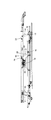
- FIG. 1 is a perspective view showing a skeleton of an ambulance vibration isolator according to an embodiment of the present invention.
- FIG. 2 is a plan view of FIG.
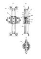
- FIG. 3 is a side view of FIG. 4A and 4B are views showing the first vibration absorbing mechanism, in which FIG. 4A is a bottom view, FIG. 4B is a side view, and FIG. 4C is a front view.
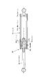
- FIG. 5 is a diagram for explaining a magnetic damper constituting the second vibration absorbing mechanism.
- 6A and 6B are diagrams showing a cent load of the upper frame and the link mechanism, where FIG. 6A shows a stable state at the bottom dead center, and FIG. 6B shows a top dead center.
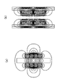
- FIG. 7A is an analysis diagram showing a magnetic flux distribution of an interlinkage magnetic flux type magnetic damper
- FIG. 7B is a magnetic flux distribution of a magnetic flux focusing type magnetic damper.
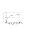
- FIG. 8 is a diagram showing a BH curve of the yoke used in the analysis of FIG.
- FIG. 9 shows an electromagnetic force corresponding to the speed generated in each linkage magnetic field type and magnetic flux focusing type damper when the moving speed of copper is 0.05 m / s, 0.1 m / s, and 0.3 m / s. It is the figure which showed the analysis result.
- FIG. 8 is a diagram showing a BH curve of the yoke used in the analysis of FIG.
- FIG. 9 shows an electromagnetic force corresponding to the speed generated in each linkage magnetic field type and magnetic flux focusing type damper when the moving speed of copper is 0.05 m / s, 0.1 m / s, and 0.3 m / s. It is the figure which showed the analysis result
- FIG. 10A is a diagram showing load-displacement characteristics of an interlinkage magnetic flux type magnetic damper
- FIG. 10B is a load of a magnetic flux focusing type magnetic damper.
- FIG. 11A shows the load-velocity characteristics of an interlinkage magnetic flux type magnetic damper
- FIG. 11B shows the load of a flux-concentration magnetic damper.
- -It is the figure which showed the speed characteristic.
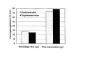
- FIG. 12 is a diagram showing analysis values and experimental values of the attenuation coefficient of each model used in the experimental example.
- FIG. 12 is a diagram showing analysis values and experimental values of the attenuation coefficient of each model used in the experimental example.
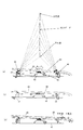
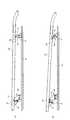
- FIG. 13 is a diagram of an ambulance vibration isolation stand in which a base frame, an upper frame, a front link mechanism, and a rear link mechanism are extracted, and (a) is a substantially horizontal position located at the top dead center of St. Road. The state of the posture is shown, and (b) is a diagram showing the state of the inclined posture located at the bottom dead center.
- FIG. 14 is a view showing the structure of the front link mechanism control means, (a) is a view in which the front link mechanism control means is assembled to an anti-vibration stand for ambulance, and (b) is an anti-vibration for ambulance. It is the figure which showed the front part link mechanism control means before attaching to a mount frame.
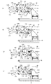
- FIGS. 15A to 15D are views showing the movement of the process of displacing and holding the upper frame in a substantially horizontal posture using the front link mechanism control means.
- FIGS. 16A to 16D are views showing the movement of the process of holding the upper frame of the front link mechanism control means displaced in a substantially horizontal posture, excluding the release lever.
- FIGS. 17A to 17D are views showing the movement of the release lever in the process of holding the upper frame of the front link mechanism control means displaced in a substantially horizontal posture.
- FIG. 18 is a view showing the structure of the rear link mechanism control means, (a) is a view in which the rear link mechanism control means is assembled to the vibration isolator for ambulances, and (b) is the vibration isolator for ambulances. It is the figure which showed the rear part link mechanism control means before the assembly
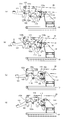
- FIGS. 19A to 19C are views showing the movement in the process of holding the upper frame displaced in a substantially horizontal posture using the rear link mechanism control means.
- the ambulance vibration isolator 1 includes a base frame 10 and an upper frame 20.
- the base frame 10 has an outer frame member 11 formed in a substantially rectangular shape in plan view.
- the outer frame member 11 has a base-side front bracket 12 that protrudes upward on the front side of the side frame 11a (the head side of a person riding on a stretcher).
- a base-side rear bracket 13 having a height lower than that of the base-side front bracket 12 is provided on the rear side of the side frame 11a (the foot side of the person riding on the stretcher).
- the upper frame 20 has an outer frame member 21 formed in a substantially rectangular shape in plan view, and an upper side front bracket 22 protruding downward is provided on the front side of the side frame 21a.
- the base-side front bracket 12 and the upper-side front bracket 22 are provided in a positional relationship such that the upper part of the base-side front bracket 12 is positioned above the lower part of the upper-side front bracket 22.
- a guide portion 21c that is curved downward toward the rear end side is formed on the rear side of the upper frame 20 so that the stretcher can be easily carried in.
- the link mechanism includes a front link mechanism 30 located on the front side of the base frame 10 and the upper frame 20, and a rear link mechanism 40 located on the rear side.
- the front link mechanism 30 includes a front link member 31 whose upper end is pivotally supported on the upper part of the base side front bracket 12 and whose lower end is pivotally supported on the lower part of the upper side front bracket 22.
- the rear link mechanism 40 has a support shaft 42 pivotally supported between a pair of base side rear brackets 13 facing in the width direction, and a lower end fixed to the support shaft 42 by welding or the like. And a rear link member 41 that is pivotally supported by the upper side rear bracket 23 provided.
- the vibration absorption mechanism includes a first vibration absorption mechanism 50 and a second vibration absorption mechanism 60.
- the first vibration absorbing mechanism 50 is a mechanism including a magnetic damper portion 510 and a magnetic spring portion 520.
- a mountain-shaped frame 15 that is bent in a substantially mountain shape near the center in the longitudinal direction of the base frame 10 has first, second, second,
- the three permanent magnets 51a, 51b, 51c are opposed to each other with a predetermined interval, and a magnet unit 51 of an attracting system in which the different poles are adjacent to each other is supported.
- a conductor 52a such as copper and a movable permanent magnet 52b are supported on the central bracket 25 provided on the upper frame 20 at a position corresponding to the angle frame 15.
- the conductor 52a is provided, for example, between the first and second permanent magnets 51a, 51b, and the movable side permanent magnet 52b is provided, for example, between the second and third permanent magnets 51b, 51c.
- a magnetic damper portion (linkage magnetic flux type magnetic damper) 510 is formed by the first and second permanent magnets 51a, 51b and the conductor 52a, and the second and third permanent magnets 51b, 51c and the movable permanent magnet 52b.
- a magnetic spring portion 520 is formed.
- the second vibration absorbing mechanism 60 includes a cylinder 61 and a flux-concentration type magnetic damper including a piston 62 that slides in the cylinder 61.
- the bottom of 61 is pivotally supported by the cylinder bracket 16 of the base frame 10, and the projecting end of the piston rod 63 to which the piston 62 is connected is pivotally supported by the piston bracket 26 of the upper frame 20, mainly in the vertical direction. Absorbs vibration.
- the cylinder 61 includes a conductor 61a such as copper formed in a cylindrical shape, preferably a cylindrical shape, and a cylindrical, preferably cylindrical iron yoke that covers the outer peripheral surface thereof. (Cylinder side yoke) It is formed with a double cylinder structure with 61b.
- a conductor 61a such as copper formed in a cylindrical shape, preferably a cylindrical shape, and a cylindrical, preferably cylindrical iron yoke that covers the outer peripheral surface thereof. (Cylinder side yoke) It is formed with a double cylinder structure with 61b.
- the piston 62 includes a plurality of annular permanent magnets 62a and an annular iron yoke (piston side yoke) 62b.
- the permanent magnet 62a and the piston side yoke 62b are supported by inserting the tip end side of the piston rod 63 made of a nonmagnetic material such as nonmagnetic stainless steel.
- the permanent magnets 62a arranged adjacent to each other are arranged with the same poles facing each other.
- the two permanent magnets 62a and 62a have the N poles opposed to each other.
- piston side yoke 62b is arrange
- the piston side yoke 62b is laminated
- a sliding member 62c for reducing sliding resistance is provided on the outer side of the piston side yoke 62b.
- the piston 62b reciprocates in the axial direction in the cylinder 61.
- the magnetic flux of the permanent magnet 62a is focused by the piston side yoke 62b and most of the magnetic flux passes through the conductor 61a, and the penetrating magnetic flux further passes through the cylinder side yoke 61b, so that there is very little magnetic flux leaking outward. Therefore, a high damping force works with the reciprocation.
- an oil damper may be used as the second vibration absorbing mechanism 60 in place of the magnetic flux focusing type magnetic damper.
- the effect of reducing the vibration transmissibility with respect to the vibration in the vertical direction is great in both the case where the oil damper is used and the case where the magnetic flux focusing type magnetic damper is used.
- the vibration isolator 1 for ambulances using a magnetic flux focusing magnetic damper was superior. This is because the oil damper has a large damping force and has a hard characteristic in the low speed region, whereas the magnetic flux focusing type magnetic damper has a small damping force at the beginning of movement, and the damping force increases as the speed increases. This is because it has the property of increasing. Therefore, it is more preferable that the magnetic flux focusing type magnetic damper is adopted as the second vibration absorbing mechanism 60 than the oil damper is adopted.
- the vibration transmissibility for the vibration in the front-rear direction can be made closer to that using a magnetic flux focusing type magnetic damper.
- the adjustment of the spring constant and damping coefficient of the magnetic damper portion 510 and magnetic spring portion 520 of the first vibration absorbing mechanism 50 and the adjustment of the weight of the guide portion 21c of the upper frame 20 are shown in FIG. It swings and displaces between the bottom dead center and the top dead center of the motion trajectory of the indicated four-bar rotation chain. That is, at the top dead center of the motion trajectory, the posture is substantially horizontal as shown in FIG. 6 (b), and at other positions, the front side is an inclined posture above the rear side, and at the bottom dead center, the inclination is inclined. The angle is maximum. Moreover, in the substantially horizontal attitude
- the front link member 31 of the front link mechanism 30 is centered on the pivotal support position with the upper portion of the base side front bracket 12 due to the acceleration in the rearward direction.
- the rear link member 41 of the rear link mechanism 40 has a pivot support position with the base side rear bracket 13 via the support shaft 42.
- the upper end side that is pivotally supported by the upper side rear bracket 23 rotates backward and tends to be displaced in a standing direction.
- the upper frame 20 tends to be displaced in a direction that assumes a substantially horizontal posture.
- the front link mechanism 30 and the rear link mechanism 40 rotate the four-nodes between the inclined posture and the substantially horizontal posture. Swing along the chain trajectory and absorb the vibration. Further, as shown in FIG. 6A, the centload is set so as to substantially coincide with the center of gravity of the upper frame 20, and the structure is less likely to move back and forth as it approaches the inclined position of the bottom dead center. For this reason, a damping force is exhibited when moving from the top dead center side to the bottom dead center side.
- the input vibration is absorbed by the damping force of the four-bar rotating chain itself, and is also absorbed by the damping forces of the first vibration absorbing mechanism 50 and the second vibration absorbing mechanism 60.
- the centload between the top dead center and the bottom dead center is set so as to substantially coincide with a virtual line passing through the center of gravity of the upper frame 20, so that the center of gravity of the stretcher and the person is also assumed to be virtual. It becomes on the line and can improve a person's sense of stability.
- the front link member 31 of the front link mechanism 30 is located on the upper side centered on the axial support position with the upper portion of the base side front bracket 12.
- the pivot support position with the lower portion of the front bracket 22 is displaced in the direction of turning forward, and the rear link member 41 of the rear link mechanism 40 is pivoted to the base side rear bracket 13 via the support shaft 42.
- the upper end side pivotally supported by the upper side rear bracket 23 tries to be displaced in a direction in which the upper side pivots forward and tilts.
- the upper frame 20 tends to be displaced in the direction of the inclined posture, it is displaced in the direction of increasing the head, and nose diving can be suppressed.
- the head side front side is stable in an inclined posture slightly higher than the substantially horizontal posture. Is preferred.
- the maximum inclination angle of the upper frame 20 with respect to the base frame 10 in the inclined posture is relative to the horizontal. It is preferably set in the range of 3 to 8 degrees, and more preferably set in the range of 4 to 6 degrees.
- the substantially horizontal posture includes not only the case where the upper frame 20 is in a horizontal (0 degree) positional relationship with respect to the base frame 10, but also the front side from the rear side to about 3 degrees. Including cases with a high slight inclination.
- the vibration absorbing mechanism includes the magnetic spring portion 520 and the above-described two types of magnetic dampers (the linkage magnetic field type magnetic damper which is the magnetic damper portion 510 of the first vibration absorbing mechanism 50 and the second magnetic damper).
- a type that combines the magnetic flux condensing type magnetic damper of the vibration absorbing mechanism 60 is preferable.
- the second vibration absorbing mechanism 60 a type in which an oil damper is combined is preferable.
- dampers a) to c) with respect to the magnetic spring portion 520 of the first vibration absorbing mechanism 50 a) a permanent magnet connected to one of the base frame or the upper frame and arranged at a predetermined interval; a conductor slidable between the permanent magnets and connected to the other of the base frame or the upper frame;
- An interlinkage magnetic damper comprising: b) a cylinder connected to one of the base frame or the upper frame, and a piston inserted in the cylinder so as to be reciprocable in the axial direction and connected to the other of the base frame or the upper frame,
- the cylinder includes a cylindrical conductor and a yoke that covers the outer peripheral surface of the conductor, and the piston is a plurality of permanent magnets arranged with the same poles facing each other along the axial direction of the cylinder.
- a magnetic flux focusing type magnetic damper comprising a yoke disposed between the adjacent permanent magnets, or c) Oil comprising a cylinder connected to one of the base frame or the upper frame, and a piston inserted in the cylinder so as to reciprocate in the axial direction and connected to the other of the base frame or the upper frame.
- a structure including any one of the dampers may be used, or a structure including any two or more combinations other than those exemplified above may be used.
- FIGS. 7 to 12 show the results shown in FIGS. 7 to 12 when the damping force of the flux-concentration type magnetic damper arranged in the repulsive magnetic field was examined.
- the analysis conditions were a residual magnetic flux density of 1.26 T and a copper electrical conductivity of 56 ⁇ 10 6 S / m.
- FIG. 8 shows the BH curve of the yoke.
- FIG. 9 shows the electromagnetic force corresponding to the speed generated in each of the linkage magnetic field type and magnetic flux focusing type dampers when the moving speed of copper is 0.05 m / s, 0.1 m / s, and 0.3 m / s. The analysis results are shown, and it can be seen that the magnetic focusing magnetic damper has a damping force about three times that of the interlinkage magnetic damper.
- the damping force was measured using a servo pulsar manufactured by Shimadzu Corporation.
- the waveform input to the server pulser is 1 to 4 Hz and a sine wave with a single amplitude of 10 mm is given in increments of 1 Hz under constant amplitude conditions to obtain the load-displacement characteristics of each magnetic damper. It was shown to.
- FIG. 11 shows the load-velocity characteristics of each magnetic damper
- FIG. 12 shows the analytical value and experimental value of the damping coefficient of each model. The error between the analytical value and the experimental value was 10% or less. From FIG.
- the flux-concentration type magnetic damper can obtain a damping force of about 2.9 times as an experimental value compared to the interlinkage type flux magnetic damper.
- the linkage magnetic field type magnetic damper is a magnet arrangement of an attraction system, and an eddy current is generated in a loop shape around the direction between the magnets of the attraction system, so that an electromagnetic force in a direction not contributing to the damping force is generated.
- the magnetic flux focusing type magnetic damper generates an eddy current in a loop shape around the axial direction, which is the direction of motion, and therefore generates a large amount of electromagnetic force in a direction effective as a damping force. Further, from the magnetic flux distribution of FIG.
- the magnetic flux focusing type magnetic damper in the magnetic flux focusing type magnetic damper, the magnetic flux is focused on the magnet gap portion by the repulsive magnet arrangement, and further, the axial center portion by the yoke arrangement between the magnets, both ends of the magnet, and the outside of the conductor.
- the magnetic flux passing through is decreasing.
- the magnetic flux deviating from the conductor is greatly reduced as compared with the interlinkage magnetic damper, and it is considered that the damping coefficient has increased.
- FIG. 13 shows the base frame 10, the upper frame 20, the front link mechanism 30, and the rear link mechanism 40 in order to make it easy to understand the displacement of the vibration isolator 1 for the ambulance 1 in accordance with the movement trajectory of the above-described four-node rotation chain.
- (A) shows the state of the substantially horizontal posture located at the top dead center of the cent road
- (b) shows the state of the inclined posture located at the bottom dead center.
- the upper frame 20 is displaced between this substantially horizontal posture and a high inclined posture on the front side.
- a treatment such as a heart massage
- an appropriate treatment is performed if the upper frame 20 is in a swingable state.
- the upper frame position holding structure is a mechanism for holding the upper frame 20 in a substantially horizontal position.
- the front link mechanism control means 100 and the rear link mechanism control means 200 are provided as the upper frame position holding structure.
- the front link mechanism control means 100 is an upper frame position holding structure used when working on the front side in an ambulance with a stretcher mounted, and the rear link mechanism control means 200 unloads the stretcher.
- the upper frame position holding structure is used when working on the rear side. Either of them may be used, but it is preferable to provide both means because the work is easily performed on the rear side when the stretcher is loaded and unloaded, and the work is easily performed on the front side after mounting.
- the front link member 31 is provided as a pair spaced apart in the width direction of the upper frame 20. They are connected by a support shaft 311 spanned between the lower portions 22a of a pair of upper side front brackets 22 that are also spaced apart in the width direction. Each end 311a of the support shaft 311 is rotatably supported by the lower portion 22a of the upper side front bracket 22, but each front link member 31 is slightly closer to the inside than each end 311a of the support shaft 311. And is fixed to the support shaft 311.
- the pair of front link members 31 are displaced synchronously with the rotation of the support shaft 311 in accordance with the relative displacement of the upper frame 20 due to the vibration input.
- the front link member 31 rotates in a predetermined direction as the support shaft 311 rotates.
- the front link mechanism control means 100 is a roller composed of two plate-like members fixed at a predetermined interval so as to protrude upward between the pair of front link members 31 on the support shaft 311.
- An engaged portion configured to include a bracket for a roller 101 and a roller 102 spanned between two plate-like members of the roller bracket 101 is provided.
- the roller bracket 101 is provided such that the protruding direction from the support shaft 311 is closer to the front than the front link member 31 as viewed from the side.
- the front link mechanism control means 100 further includes a lock member 110 having an engaging portion that engages with the roller 102 supported by the roller bracket 101 that is the above-described engaged portion, and operates the lock member 110. And an operation member 120 to be operated. By operating the operation member 120, an external force for forcibly rotating the support shaft 311 is applied.
- the lock member 110 is formed of a plate-like member, and is pivotally supported by a central mounting plate 20 a provided so that the shaft pin 111 serving as the rotation center protrudes downward at a substantially central portion in the width direction of the upper frame 20.
- it has a rear protruding piece 112 that protrudes substantially rearward, a front protruding piece 113 that protrudes substantially forward, and a lower protruding piece 114 that protrudes substantially downward.
- the rear protruding piece 112 is formed in a substantially square shape, the inner surface on the tip side is formed to be slightly curved, and serves as a guide surface 112 a that can contact the roller 102.
- a groove 112b carved from the inner surface is formed in the vicinity of the substantially bent portion closer to the shaft pin 111 than the guide surface 112a, and the roller 102 is engaged with the groove 112b.
- the operation member 120 includes an operation lever 121 and a connection member 122 that connects the operation lever 121 and the lock member 110.
- the connecting member 122 is composed of two link plates 122a and 122b whose upper ends are connected by pins 122c.
- the lower end of the rear link plate 122a is connected to the end of the front protruding piece 113 of the lock member 110 via a pin 113a, and the lower end of the front link plate 122b is fixed to the rear end 121a of the operation lever 121.
- the shaft member 123 is fixed.
- the shaft member 123 is pivotally supported by the central mounting plate 20a whose one end is positioned at a substantially central portion in the width direction, and the other end is near the front end of the upper frame 20 and is one side frame than the central mounting plate 20a. It is pivotally supported by an operating lever mounting plate 20b provided at a predetermined distance on the 21a side so as to be rotatable.
- the operation lever 121 is fixed such that the shaft member 123 penetrates in the thickness direction, the front operation portion 121b protrudes forward from the front end of the upper frame 20, and the front operation portion 121b is When an external force that is pushed down is applied, the shaft member 123 rotates.
- the operation in the front link mechanism control means 100 of this embodiment is performed as follows. First, as shown in FIGS. 15A and 16A, it is assumed that the upper frame 20 is in an inclined state in which the front side is positioned upward. In this state, when the upper frame 20 needs to be in a substantially horizontal posture, the front operation portion 121b of the operation lever 121 is depressed in the direction of arrow A. When the front side operation unit 121b is stepped on, as shown in FIGS. 15B and 16B, the shaft member 123 rotates according to the stepping amount, and accordingly, the upper end of the front side link plate 122b is slightly forward. It is pulled up in the direction of turning upward (arrow B direction).
- the position where the upper frame 20 is in a substantially horizontal position is the top dead center of the movement locus of the four-barrel rotation chain. Therefore, when the front operation portion 121b of the operation lever 121 is further stepped on, the lock member 110 causes the shaft pin 111 to move. The center further rotates rearward (in the direction of arrow C), and the groove 112b engages with the roller 102 as shown in FIGS. 15 (d) and 15 (d). As a result, locking is performed and the upper frame is held in a horizontal posture.
- the direction in which the operation lever 121 is operated and locked (the direction in which the roller 102 is engaged with the groove 112b of the lock member 110) and the direction in which the upper frame 20 is displaced in a substantially horizontal posture are substantially coincident.
- the operation direction is a direction in which the front side of the upper frame is lowered and pushed backward, the upper frame 20 is displaced and held in a substantially horizontal posture by simply depressing the operation lever 121. can do.
- a release lever 125 is separately provided for easy operation. As shown in FIGS. 14 and 17, the release lever 125 is pivotally supported by the central mounting plate 20 a located at the substantially central portion in the width direction, and the other end is near the front end of the upper frame 20. It is connected to a shaft member 124 pivotally supported by a release lever mounting plate 20c provided at a predetermined distance from the central mounting plate 20a on the other side frame 21a side.
- the release front link plate 126b whose upper end is connected to the shaft member 124, and a release rear link plate 126a whose front end is connected to the front link plate 126b via a pin 127.
- the release-side rear link plate 126a extends substantially horizontally, and the rear end thereof is connected to the lower end of the downward projecting piece 114 of the lock member 110 to the pin 114a.
- the rear link mechanism control means 200 has a rotating member 210, a plate member 220, a rod member 230, and a slope 240 as an operation member.
- the pivot member 210 has an upper end 210 a that is pivotally supported via a pin 23 a on the upper rear bracket 23 of the upper frame 20 on which the upper end of the rear link member 41 is pivotally supported, and the rear side of the rear link member 41. Placed in.
- the rotating member 210 is formed in a substantially U-shaped cross section with such a width that it can cover and overlap a part of the rear end surface and side surface of the rear link member 41.
- the rotating member 210 is longer in the vertical direction than the rear link member 41, the midway part 210 b is fixed at the lower end of the rear link member 41, and is pivotally supported between the pair of base side rear brackets 13. It contacts the side surface of the support shaft 42.
- the contact surface side of the midway portion 210b is cut out in an arc shape so as to fit the side surface of the support shaft 42.
- this shape is not essential, and the rotation of the rotation member 41 is achieved by contact. It is only necessary to perform a stopper function for stopping.
- the slope 240 is provided in the guide portion 21c on the rear side of the upper frame 20. Specifically, one end of the slope 240 is pivotally supported with respect to the guide portion 21c via the shaft 241 and tilts backward from the standing position shown in FIGS. 18A and 19A to guide the slope 240. It is used by being pulled down so as to be almost an extension of the portion 21c. As shown in FIG. 19C, a stopper member 21d is provided on the side portion of the guide portion 21c, and tilts until the side portion of the slope 240 comes into contact with the stopper member 21d. The slope 240 is used by being pulled backward when the stretcher is loaded and unloaded, and is provided to smoothly guide the wheels of the stretcher onto the upper frame 20, and is set to the standing position after the stretcher is mounted.
- the plate member 220 has a predetermined length, one end is pivotally supported on the shaft 241 on which the slope 240 is pivotally supported, and the other end is pivotally supported on the other end 230 b of the rod member 230.
- One end 230 a of the rod member 230 is pivotally supported by the lower end 210 c of the rotating member 210.
- the shaft 241 rotates with the rotation of the slope 240, and the plate member 220 is provided to rotate with the rotation of the shaft 241, and the rotation member with the tilting operation of the slope 240. Since the 210, the plate member 220, and the rod member 230 operate, the slope 240 functions as an operation member in the rear link mechanism control means 200.
- the rod member 230 in the standing state of the slope 240, as shown in FIG. 19A, the rod member 230 is substantially horizontal and the plate member 220 is in a substantially vertical positional relationship with respect to the rod member 230.
- the lower end 210c is displaced rearward, and the midway part 210b is separated from the support shaft 42.
- the positional relationship among the rotating member 210, the plate member 220, and the rod member 230 does not change.
- the rear hatch of the ambulance is opened and the slope 240 is pulled down to be used.
- the operator is positioned outside the rear hatch, and the slope 240 is moved to the front side ( The operation is performed so as to pull it out to the right side of FIG.
- the midway part 210b of the rotating member 210 comes into contact with the support shaft 42 as shown in FIG.
- the rear link member 41 is rotated clockwise around the support shaft 42 in the clockwise direction by the force, and is displaced in the standing direction.
- the upper frame 20 is in a substantially horizontal posture.
- the slope 240 is pulled down until it comes into contact with the stopper member 21d, but the plate member 220 has the other end centered on the shaft 241. It rotates clockwise from the downward position to the front side. Therefore, the other end 230b of the rod member 230 is displaced upward due to the displacement of the plate member 220, and when the upper frame 20 in FIG. And are almost in a straight line. As a result, the middle part 210b of the rotating member 210 is pressed against the support shaft 42, and even if a force in the direction of the bottom dead center is applied to the upper frame 20, it is locked without moving and the substantially horizontal posture is maintained.
- the ambulance anti-vibration stand 1 of the present embodiment is such that the centload of the four-bar rotation chain substantially coincides with a virtual line passing through the center of gravity of the upper frame from the top dead center to the bottom dead center. It is preferable that As a result, the bottom dead center is less likely to generate a rotational motion that combines the longitudinal motion and the vertical motion, and as it moves in the direction of the bottom dead center, the four-bar rotation chain becomes difficult to move and exhibits a damping force. It becomes a configuration that can That is, usually bottoming occurs at the bottom dead center, and impact vibration is input to the human side, but the bottom dead center becomes more stable with the spring force, damping force, and mass, and the link operating efficiency is further improved. Since the damping action associated with the reduction functions, bottoming can be suppressed, and the characteristic is close to a rigid body at the bottom dead center.
- the vibration isolator 1 for the ambulance is configured to absorb by converting into the single pendulum motion along the motion trajectory of the four-bar rotation chain, it is rigid with respect to the vibration in the vertical direction.
- the vibration absorption mechanism that performs the vibration suppression function in the vertical direction and the vibration absorption mechanism that performs the vibration suppression function in the front-rear direction are separately provided by taking advantage of the characteristics.
- the vibration transmissibility of the resonance point with respect to the front and rear input vibrations can be reduced.
- phase lag for example, a phase lag of about 90 degrees
- the unsprung mass has increased along with the increase in the diameter and width of vehicle tires, the loading weight has increased, and the suspension has been made with a firm spring. Reduce ride comfort.
- the vibration isolator for ambulance 1 of the present embodiment the vibration transmissibility of the resonance point in the vertical direction becomes small (resonance region becomes narrow) due to the characteristics of the rigid body, and it is easy to match the two.
- the vibration energy generated by the vertical direction input is converted into the vertical direction by converting the place where the vibration transmissibility is 1 in the characteristic of the rigid body into the front-rear direction in the equilibrium state near the bottom dead center where micro vibrations are repeated.
- the vibration transmissibility falls below 1 and becomes an attenuation region, and the vibration energy in the vertical direction is attenuated.
- vibration can be attenuated using the weight of the person, and because it constantly tries to return to a stable state, the feeling of rocking of the head is reduced. It is a structure.
- the vibration absorbing mechanism a structure in which a linkage magnetic flux type magnetic damper, a magnetic focusing type magnetic damper and a magnetic spring are used in combination can exhibit higher vibration absorption characteristics.
- a structure in which a linkage magnetic flux type magnetic damper, a magnetic focusing type magnetic damper and a magnetic spring are used in combination can exhibit higher vibration absorption characteristics.
- a cylindrical magnetic flux concentrating magnetic damper having a repulsive magnet arrangement and a conductor arranged around a permanent magnet is used, a high damping force can be exhibited.
Landscapes
- Engineering & Computer Science (AREA)
- General Engineering & Computer Science (AREA)
- Mechanical Engineering (AREA)
- Public Health (AREA)
- Physics & Mathematics (AREA)
- Health & Medical Sciences (AREA)
- Acoustics & Sound (AREA)
- Aviation & Aerospace Engineering (AREA)
- Electromagnetism (AREA)
- Life Sciences & Earth Sciences (AREA)
- Animal Behavior & Ethology (AREA)
- General Health & Medical Sciences (AREA)
- Veterinary Medicine (AREA)
- Rehabilitation Tools (AREA)
- Vibration Prevention Devices (AREA)
Abstract
Afin de maintenir un cadre supérieur apte à osciller le long de la trajectoire de mouvement d'une chaîne de manivelle quadrique qui prend une posture inclinée et une posture approximativement horizontale dans la posture approximativement horizontale par une opération simple lorsqu'elle est nécessaire, un cadre supérieur (20) apte à osciller le long de la trajectoire de mouvement d'une chaîne de manivelle quadrique entre une posture inclinée et une posture approximativement horizontale est déplacé de façon forcée vers la position approximativement horizontale et maintenu. Un moyen (100) de commande d'un mécanisme de liaison avant applique une force externe pour pousser vers le bas un élément de fonctionnement (120) pour commander par là un mécanisme de liaison avant (30), de telle sorte que le côté avant du cadre (20) supérieur est déplacé vers l'arrière tout en étant abaissé. La direction du déplacement pour amener le cadre supérieur (20) dans la posture approximativement horizontale et la direction d'un actionnement pour verrouiller le mécanisme de liaison avant (30) ou un mécanisme de liaison arrière (40) par l'actionnement de l'élément d'actionnement devient approximativement la même direction que l'autre, et en conséquence deux mouvements, un mouvement de déplacement vers la posture approximativement horizontale et un mouvement de verrouillage peuvent être effectués seulement par l'actionnement de l'élément d'actionnement dans une direction prédéterminée.
Priority Applications (1)
| Application Number | Priority Date | Filing Date | Title |
|---|---|---|---|
| US14/356,005 US9345630B2 (en) | 2011-11-08 | 2012-11-02 | Upper frame position holding structure and ambulance vibration-proof rack having upper frame position holding structure |
Applications Claiming Priority (2)
| Application Number | Priority Date | Filing Date | Title |
|---|---|---|---|
| JP2011-244205 | 2011-11-08 | ||
| JP2011244205A JP5930456B2 (ja) | 2011-11-08 | 2011-11-08 | 救急車用防振架台 |
Publications (1)
| Publication Number | Publication Date |
|---|---|
| WO2013069578A1 true WO2013069578A1 (fr) | 2013-05-16 |
Family
ID=48289953
Family Applications (1)
| Application Number | Title | Priority Date | Filing Date |
|---|---|---|---|
| PCT/JP2012/078527 Ceased WO2013069578A1 (fr) | 2011-11-08 | 2012-11-02 | Structure de maintien de position de cadre supérieur et support d'isolement de vibrations d'ambulance présentant une structure de maintien de position d'un cadre supérieur |
Country Status (3)
| Country | Link |
|---|---|
| US (1) | US9345630B2 (fr) |
| JP (1) | JP5930456B2 (fr) |
| WO (1) | WO2013069578A1 (fr) |
Families Citing this family (3)
| Publication number | Priority date | Publication date | Assignee | Title |
|---|---|---|---|---|
| JP2019202749A (ja) * | 2018-05-22 | 2019-11-28 | デルタ工業株式会社 | サスペンション機構、マルチサスペンション機構及びダンパー |
| JP7555098B2 (ja) * | 2020-07-13 | 2024-09-24 | 株式会社赤尾 | 救急車用防振架台 |
| JP7757995B2 (ja) * | 2023-02-08 | 2025-10-22 | トヨタ自動車株式会社 | 車両用制御装置 |
Citations (4)
| Publication number | Priority date | Publication date | Assignee | Title |
|---|---|---|---|---|
| JPH0531140A (ja) * | 1991-07-26 | 1993-02-09 | Shinmeiwa Ribitetsuku Kk | 救急自動車におけるストレツチヤーの防振移載装置 |
| JP2000126233A (ja) * | 1998-10-21 | 2000-05-09 | Deruta Tsuuringu:Kk | 救急車用除振架台 |
| JP2000245774A (ja) * | 1999-03-02 | 2000-09-12 | Deruta Tsuuringu:Kk | ストレッチャ除振台のロック機構 |
| JP2006075203A (ja) * | 2004-09-07 | 2006-03-23 | Toyota Motor Corp | 車両用可動防振架台 |
Family Cites Families (12)
| Publication number | Priority date | Publication date | Assignee | Title |
|---|---|---|---|---|
| BE487263A (fr) * | 1947-12-16 | |||
| US3644944A (en) * | 1970-05-20 | 1972-02-29 | Ferno Washington | Ambulance cot construction |
| DE3608448C2 (de) * | 1986-02-17 | 1994-05-05 | Miesen Fahrzeug | Krankentransportfahrzeug mit einer Trageneinrichtung |
| FR2651998B1 (fr) * | 1989-09-21 | 1997-05-30 | Heuliez Henri France Design | Table de support de brancard notamment destinee a l'equipement d'ambulances. |
| DE4112270C1 (en) * | 1991-04-15 | 1992-07-16 | Utila Geraetebau Gmbh & Co Kg, 5000 Koeln, De | Releasable ambulance stretcher support platform - has its middle section secured to horizontal, transverse swivel axis with ends fitted to holder on vehicle |
| DE4340358C2 (de) * | 1992-12-05 | 2003-06-05 | Joachim Werker | Neigungsverstellbare Krankentransporteinrichtung in einem Fahrzeug |
| DE19607899C2 (de) * | 1996-03-01 | 1999-11-25 | Bruno Minig | Behandlungstisch für Rettungswagen mit einer Tragenbühne |
| NZ514833A (en) * | 2001-10-16 | 2004-09-24 | Howard Wright Ltd | Strecher Suspension Linkages |
| ES2364842B1 (es) * | 2009-01-29 | 2012-08-03 | Productos Metálicos Del Bages, S.L. | Porta-camilla. |
| JP5634058B2 (ja) | 2009-12-18 | 2014-12-03 | 宗一 今井 | ロータリーガン用ノズル |
| JP5818135B2 (ja) | 2010-06-04 | 2015-11-18 | 株式会社デルタツーリング | 救急車用防振架台 |
| DE102014202033B4 (de) * | 2014-02-05 | 2017-07-06 | Siemens Healthcare Gmbh | Mobiles medizinisches Gerät sowie Verfahren zur Steuerung einer Bewegung des mobilen medizinischen Geräts |
-
2011
- 2011-11-08 JP JP2011244205A patent/JP5930456B2/ja active Active
-
2012
- 2012-11-02 US US14/356,005 patent/US9345630B2/en not_active Expired - Fee Related
- 2012-11-02 WO PCT/JP2012/078527 patent/WO2013069578A1/fr not_active Ceased
Patent Citations (4)
| Publication number | Priority date | Publication date | Assignee | Title |
|---|---|---|---|---|
| JPH0531140A (ja) * | 1991-07-26 | 1993-02-09 | Shinmeiwa Ribitetsuku Kk | 救急自動車におけるストレツチヤーの防振移載装置 |
| JP2000126233A (ja) * | 1998-10-21 | 2000-05-09 | Deruta Tsuuringu:Kk | 救急車用除振架台 |
| JP2000245774A (ja) * | 1999-03-02 | 2000-09-12 | Deruta Tsuuringu:Kk | ストレッチャ除振台のロック機構 |
| JP2006075203A (ja) * | 2004-09-07 | 2006-03-23 | Toyota Motor Corp | 車両用可動防振架台 |
Also Published As
| Publication number | Publication date |
|---|---|
| JP2013099399A (ja) | 2013-05-23 |
| US9345630B2 (en) | 2016-05-24 |
| JP5930456B2 (ja) | 2016-06-08 |
| US20140300123A1 (en) | 2014-10-09 |
Similar Documents
| Publication | Publication Date | Title |
|---|---|---|
| JP3115864B2 (ja) | 救急車用除振架台 | |
| JP6735826B2 (ja) | 椅子及び座の支持機構 | |
| CN101761600B (zh) | 用于减振的装有弹簧的振动系统 | |
| US20100167883A1 (en) | Exercise device with adaptive curved track motion | |
| EP2960890A1 (fr) | Simulateur de mouvement | |
| JP5930456B2 (ja) | 救急車用防振架台 | |
| US11253077B2 (en) | Chair with return force mechanism | |
| JPWO2017145271A1 (ja) | 椅子及び座の支持機構 | |
| JP2000234649A (ja) | サスペンションユニット | |
| JP2004353770A (ja) | サスペンションユニット | |
| JP2019037383A (ja) | 椅子 | |
| JP4349649B2 (ja) | 対象物設置機構 | |
| CN211442046U (zh) | 一种多维度减震座椅 | |
| JP2000245774A (ja) | ストレッチャ除振台のロック機構 | |
| JP2008128315A (ja) | サスペンションユニット | |
| JP5818135B2 (ja) | 救急車用防振架台 | |
| JP3139781U (ja) | スライド式ステッパー | |
| US20230310929A1 (en) | Two-person exercise wheel mechanism | |
| JP2846866B2 (ja) | 移動家具 | |
| KR102344794B1 (ko) | 실내용 외발 자전거 | |
| KR100898934B1 (ko) | 라이드봇의 안장 어셈블리 | |
| CN206968755U (zh) | 一种避震机构及儿童用品 | |
| JP2581538Y2 (ja) | 救急用ベッドの防振基台 | |
| JP5926434B1 (ja) | 胸部支持機構および胸部支持機構一体型フレーム | |
| JP3140879U (ja) | 騎馬のシミュレーション装置 |
Legal Events
| Date | Code | Title | Description |
|---|---|---|---|
| 121 | Ep: the epo has been informed by wipo that ep was designated in this application |
Ref document number: 12847424 Country of ref document: EP Kind code of ref document: A1 |
|
| WWE | Wipo information: entry into national phase |
Ref document number: 14356005 Country of ref document: US |
|
| NENP | Non-entry into the national phase |
Ref country code: DE |
|
| 122 | Ep: pct application non-entry in european phase |
Ref document number: 12847424 Country of ref document: EP Kind code of ref document: A1 |