WO2013105241A1 - Tête d'arrosage - Google Patents
Tête d'arrosage Download PDFInfo
- Publication number
- WO2013105241A1 WO2013105241A1 PCT/JP2012/050427 JP2012050427W WO2013105241A1 WO 2013105241 A1 WO2013105241 A1 WO 2013105241A1 JP 2012050427 W JP2012050427 W JP 2012050427W WO 2013105241 A1 WO2013105241 A1 WO 2013105241A1
- Authority
- WO
- WIPO (PCT)
- Prior art keywords
- valve body
- spring
- nozzle
- sprinkler head
- head according
- Prior art date
- Legal status (The legal status is an assumption and is not a legal conclusion. Google has not performed a legal analysis and makes no representation as to the accuracy of the status listed.)
- Ceased
Links
Images


Classifications
-
- A—HUMAN NECESSITIES
- A62—LIFE-SAVING; FIRE-FIGHTING
- A62C—FIRE-FIGHTING
- A62C31/00—Delivery of fire-extinguishing material
- A62C31/02—Nozzles specially adapted for fire-extinguishing
-
- A—HUMAN NECESSITIES
- A62—LIFE-SAVING; FIRE-FIGHTING
- A62C—FIRE-FIGHTING
- A62C37/00—Control of fire-fighting equipment
- A62C37/08—Control of fire-fighting equipment comprising an outlet device containing a sensor, or itself being the sensor, i.e. self-contained sprinklers
- A62C37/10—Releasing means, e.g. electrically released
- A62C37/11—Releasing means, e.g. electrically released heat-sensitive
- A62C37/12—Releasing means, e.g. electrically released heat-sensitive with fusible links
Definitions
- the present invention relates to a fire extinguishing sprinkler head.
- the sprinkler head is installed on a ceiling surface or a wall surface in a building, has a nozzle that can be connected to a pipe connected to a water supply source at one end, and a thermal decomposition section at the other end.
- the heat-sensitive operating part supports a valve body that closes the nozzle.
- the sprinkler head there is a sprinkler head corresponding to a negative pressure sprinkler facility in which the inside of a pipe has a negative pressure (see, for example, Patent Document 1).
- the sprinkler head of Patent Document 1 shown in FIG. 9 is provided with a “spring” that urges a “sealing plate” that closes a nozzle connected to a water supply pipe in a direction to separate it from the nozzle end.
- the “sealing plate” is supported by the thermal decomposition part in which the “low melting point alloy” is incorporated.
- the “sealing plate” The support of the “plate” is released, and the “sealing plate” can be opened from the nozzle end.
- the pressure inside the nozzle is negative and the “sealing plate” is adsorbed to the nozzle end, but the “sealing plate” is against the negative pressure inside the nozzle by the biasing force of the “spring”. And the nozzle is opened.
- the above-mentioned sprinkler head urges the entire circumference of the “sealing plate” by the “spring”.
- the urging force of the “spring” must be increased as the nozzle diameter increases.
- the “sealing plate” separated from the nozzle is sucked by the negative pressure in the nozzle to prevent the nozzle from being closed again.
- An object of the present invention is to provide a sprinkler head capable of preventing the nozzle from being closed again due to suction by a negative pressure.
- the present invention provides the following sprinkler head. That is, the present invention has a nozzle that can be connected to a pipe connected to a water supply source at one end of the main body, and is engaged with the tip of a frame portion extending in the direction of water discharge from the vicinity of the outlet of the nozzle by the heat of fire.
- the nozzle is closed by the valve body supported by the thermal decomposition part that performs the decomposition operation, the spring provided near the nozzle outlet pulls the valve body away from the nozzle outlet, and the spring releases the coaxial state of the nozzle and the valve body It is characterized by energizing the valve body.
- the sprinkler head having the above structure is installed in a negative pressure sprinkler facility in which the inside of the pipe has a negative pressure.
- the thermal decomposition part is actuated by heat at the time of fire and the support of the valve body is released, the valve body is pulled away from the nozzle outlet by the force of the spring and opened. Furthermore, in order to maintain the state in which the valve body is separated from the nozzle outlet, the opened valve body is again sucked by the negative pressure in the nozzle, and the nozzle is blocked by keeping the shaft of the nozzle and the shaft of the valve body coaxial. To prevent.
- the valve body When the valve body is opened, the axis of the nozzle and the axis of the valve body, which are coaxial in the state where the valve body is closed, are released from the coaxial state.
- the valve body When the valve body is opened, if the nozzle and the valve body are in a coaxial state, the valve body is likely to be sucked to the nozzle side due to the negative pressure in the nozzle, but in the state where the valve body is opened, the nozzle and the valve body When the axis is not coaxial, the range over which the force for sucking the valve body toward the nozzle is reduced by the negative pressure in the nozzle.
- the valve body can be prevented from being sucked to the nozzle side.
- a spring is attached to the valve body, and the central axis of the valve body is inclined with respect to the central axis of the nozzle when the spring is unloaded.
- the central axis of the valve element is inclined with respect to the central axis of the nozzle, so that it is inclined when water is discharged from the nozzle. It collides with the valve body in the state. Since the valve body is inclined, the valve body is scattered in an oblique direction, and is discharged to the outside of the sprinkler head without interfering with a deflector installed on the extension of the central axis of the nozzle.
- the sprinkler head when the sprinkler head is actuated by increasing the biasing force of the spring, it is possible to blow off the valve body to the outside of the sprinkler head by the biasing force of the spring.
- the valve body in a downward-type sprinkler head where the nozzle water discharge direction is set downward, when the sprinkler head is actuated, the valve body is displaced obliquely downward by its own weight and the bias of the spring, leaving the nozzle end, The valve body and the spring can be discharged to the outside of the sprinkler head without interfering with the deflector installed on the extension of the central axis.
- one end side of the spring is a valve body holding portion that holds the valve body, and the other end side is configured as a support portion installed in the vicinity of the nozzle.
- the wire-shaped spring material can be bent.
- the valve body holding portion is bent along the outer peripheral portion of the valve body so as to cover the upper surface and the lower surface of the valve body and the valve body is held, the valve body can be fixedly installed on the spring.
- the spring itself can be enlarged, and the amount of displacement and the biasing force by the spring can be increased.
- the spring support portion is inserted through the annular projection at the nozzle outlet.
- the present invention is configured by arranging a connecting portion connecting the valve body holding portion and the support portion in a direction rotated by 90 ° from the frame. According to this, when the sprinkler head is actuated, the shaft of the valve body is prevented from being directed toward the frame, and the valve body can be prevented from colliding with the ram due to the momentum of water discharged from the nozzle.
- the spring biases a part of the outer peripheral portion outside the nozzle on the nozzle side surface of the valve body.
- the spring urges the entire circumference of the valve body, and the direction in which the spring urges the valve body is the water discharge direction of the nozzle.
- the valve body did not open unless the urging force was applied.
- the valve body is always inclined to the valve body by being concentrated and biased in a direction in which the axis of the nozzle and the axis of the valve body are different, for example, only in a part of the outer periphery of the valve body. Such a force or a force for releasing the coaxial state of the valve body and the nozzle is applied.
- the valve body When the thermal decomposition section is disassembled, the valve body is tilted by the spring, and the nozzle body is released from the nozzle outlet while releasing the coaxial state of the valve body and the nozzle, so that the nozzle can be opened with a small force.
- the nozzle body When removing the suction cup that is adsorbed to the glass, it is difficult to remove the suction cup by pulling the center of the suction cup, but it is the same principle that you can easily remove the suction cup by hitting the edge of the suction cup. .
- the spring has a ring shape with a notch, and each end is bent away from each other.
- the spring By forming the spring in a ring shape, it can be installed by being inserted into the outer periphery of the nozzle outlet, whereby the spring that biases only a part of the outer peripheral portion of the valve body can be positioned. Further, by bending each end of the ring in a direction away from each other, it is possible to secure the amount of displacement in the axial direction of the ring at the notch portion, and it is possible to bias only the portion in contact with the notch portion of the valve body.
- the spring has a ring shape, a part of the peripheral edge of the ring is formed to extend outward, and the extension part is bent to form a leaf spring part.
- the spring can be installed by being inserted into the outer periphery of the nozzle outlet by making it into a ring shape, further extending a part of the ring periphery outward, and bending the extended part to form a leaf spring part Thereby, only the part which the leaf
- the valve body is formed with a spring locking portion on the outer periphery of the valve body where the spring is locked.
- the spring is formed with an engaging portion with the main body that prevents rotation.
- the engaging portion By providing the engaging portion with the main body, it is possible to prevent the spring from rotating and deviating from a predetermined biasing position.
- the sprinkler head is an upward type sprinkler head in which the water discharge direction of the nozzle is upward.
- the valve body can be surely pulled away from the nozzle end and opened when the thermal decomposition section of the sprinkler head is activated. Further, the valve body can be discharged to the outside of the sprinkler head by the water discharged from the nozzle.
- the valve body of the sprinkler head installed in the negative pressure sprinkler facility is spring-biased, and the valve body is opened in a tilted state to separate the valve body from the nozzle end. It is possible to provide a sprinkler head that requires only a small force and prevents the valve element once pulled away from the nozzle from being sucked by the negative pressure in the nozzle and closing the nozzle again.
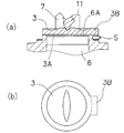
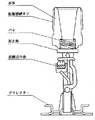
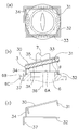
- Front view of the sprinkler head of the present invention is an enlarged cross-sectional view of the valve body portion: (a) normal operation, (b) operation System diagram of sprinkler equipment in which the sprinkler head of the present invention is installed Example of leaf spring deformation: (a) normal operation, (b) operation Side view of the leaf spring of FIG. Modified example of valve body: (a) Enlarged sectional view of valve body part, (b) Plan view of valve body Cross section of conventional sprinkler head Sectional drawing of the sprinkler head of 2nd Embodiment 10A is a plan view of only the valve body and the spring portion of FIG. 10, FIG. 10B is an enlarged sectional view of the valve body portion of FIG.
- FIG. 10C is a side view of only the spring portion.
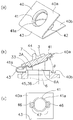
- A The perspective view of the spring modification 1 of 2nd Embodiment,
- (b) The expanded sectional view (after an action
- A The perspective view of the spring modification 2 of 2nd Embodiment,
- (b) The state which incorporated said spring in the sprinkler head (only a spring is shown in figure)
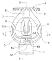
- the sprinkler head A includes a main body 1, a deflector 2, a valve element 3, a thermal decomposition unit 4, and a thermal element 5.
- the main body 1 has a male screw connected to a fire extinguishing equipment pipe on the outer peripheral surface, and a nozzle 6 capable of discharging water in the pipe is bored inside.
- a nozzle 6 capable of discharging water in the pipe is bored inside.
- two frames 7 extending from the end face 6A in the water discharge direction of the nozzle 6 (upward direction in FIGS. 1 and 2) are provided. Boss portions 8 that intersect on the axis of the nozzle 6 are formed.
- a deflector 2 that causes water discharged from the nozzle 6 to collide and scatter in four directions is fixedly installed at the tip of the boss 8.
- the deflector 2 has a disk shape, and a plurality of notches are formed on the periphery (the notches are not shown in FIG. 2).
- a female screw 8 ⁇ / b> A is formed inside the boss portion 8.
- An impress screw 21 (to be described later) is screwed into the female screw 8A, and the tip of the impress screw 21 engages the thermal decomposition portion 4.
- a flange 6B for locking a spring S described later is formed, and a recess 6C is further formed in the flange.
- the valve body 3 closes the nozzle 6, is disposed at the outlet end of the nozzle 6, and is pressed toward the nozzle 6 by a thermal decomposition unit 4 described later.
- a sealing material 3 ⁇ / b> A is interposed between the valve body 3 and the end surface 6 ⁇ / b> A of the nozzle 6.
- 3 A of sealing materials are affixed on the valve body 3 side with the adhesive, However, You may affix on the end surface 6A of the nozzle 6.
- a spring S is installed on the nozzle end surface 6A side of the valve body 3 and biases a part of the outer peripheral portion of the valve body 3 in the direction in which the valve body 3 opens.
- the spring S has a ring shape as shown in FIG. 3 and is inserted from the nozzle end face 6 ⁇ / b> A to the outer periphery of the nozzle 6.
- An extension part S1 (indicated by a dotted line in FIG. 3) extending outward is formed on a part of the outer peripheral edge of the spring S, and the extension part S1 is bent to provide a spring part S2. Yes.
- the spring portion S2 can be installed by extending inward from the inner peripheral edge of the ring portion.
- valve part 3 Only part of the outer periphery of the valve body 3 is biased in the opening direction by the spring part S2, and when the thermal decomposition part 4 is disassembled, the valve part 3 can be pulled away from the nozzle end surface 6A by the action of the spring part S2. it can.
- An engaging portion S3 extending so as to be engaged with the collar portion 6B of the main body 1 is formed on the side facing the spring portion S2.
- the distal end S4 (shown by the dotted line in the figure) of the engaging portion S3 is formed wide, and when the spring S is inserted through the outer peripheral portion of the nozzle 6, the engaging portion S3 is placed in the recess 6C of the flange portion 6B. When bent and installed, the tip S4 is engaged with the flange portion 6B.
- the spring S By engaging the engagement portion S3 with the inside of the recess 6, the spring S is prevented from rotating. Further, the engagement of the tip S4 of the engagement portion S3 with the flange portion 6B has an effect of preventing the spring S from falling off.
- the engaging portion S3 is provided only at one place. However, since the concave portion 6C of the main body 1 is provided at two places, it is possible to provide two engaging portions S3 according to this. In this case, the extending portion S1 can be provided between the two engaging portions S3, for example, on one frame 7 side.
- the thermal decomposition unit 4 includes a lever 10, a support 11, and a balance 12.
- the thermal decomposition unit 4 is configured by combining each part and a thermal body 5 described later, and each part is assembled in a state where a load is applied.
- the lever 10 has an L-shaped cross section, and a hemispherical groove 10A is engraved on the surface on the boss portion 8 side, and a V-shaped groove 10B is engraved on the back surface inside the hemispherical groove 10A.
- the support 11 has a substantially elliptical shape, and a hole 11A is formed in the center.
- An engagement branch 11B is bent outward from the hole 11A from the end of the hole, and a support branch 11C is formed from the other end of the hole 11A. It is bent in the same direction as the engaging branch 11B. Both ends of the column 41 are knife edges.
- the balance 12 has a sickle neck shape with one wide end, a hemispherical protrusion 12A is formed on the wide width portion, and an engagement portion 12B that is bent in an oblique direction is formed on the other end.
- the heat sensitive body 5 includes a cylinder 14, a fusible alloy 15, and a piston 16.
- the cylinder 14 has a bottomed cylindrical shape, and the fusible alloy 15 is placed inside.
- the fusible alloy 15 is integrated by injecting and hardening a molten alloy material into the cylinder 14. Further, the soluble alloy 15 shown in the drawing may be inserted into the cylinder 14 in advance and integrated.
- a mortar-shaped engagement hole 14 ⁇ / b> A is formed on the outer side of the bottom surface of the cylinder 14.
- the heat sensitive body 5 having the above-described configuration is incorporated in the lever 10, the movable piece 11, and the balance 12 to constitute a unit of the heat-sensitive decomposition unit 4.
- the structure of the unit is shown below.
- the hemispherical groove 10 ⁇ / b> A of the lever 10 is engaged with the hemispherical tip of the impress screw 21, and the end of the lever 10 is engaged with the engaging portion 12 ⁇ / b> B of the balance 12. Further, the V-shaped groove 10 ⁇ / b> B of the lever 10 is engaged with one end of the column 11, and the other end of the column 11 is engaged with the V-shaped groove of the valve body 3.
- the balance 12 engaged with the end of the lever 10 is inserted through the hole 11A of the support 11 and the lower surface in FIG. 2 is on the support branch 11C of the support 11.
- An engagement hole 14 ⁇ / b> A of the cylinder 14 is engaged with the engagement branch 11 ⁇ / b> B of the column 11.
- the hemispherical protrusion 12A of the balance 12 is engaged with the hole 16A of the piston 16 inserted into the cylinder 44.
- the thermal decomposition part 4 is in a state in which a load is always applied by the valve body 3 and the impress screw 21, and a force acts from the engaging branch 11 ⁇ / b> B of the column 11 to the cylinder 14, and A force acts on the piston 16 and a compressive force acts on the fusible alloy 15.
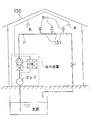
- the sprinkler head of the present invention is installed in a negative pressure sprinkler facility, and is maintained so that the inside of the pipe has a negative pressure. Since the negative pressure sprinkler equipment is described in Japanese Patent No. 3264939 and Japanese Patent Application Laid-Open No. 2004-201746, detailed description thereof is omitted.
- the sprinkler head A has a male screw 5 of the sprinkler head SH connected to a standing portion 131 of a fire extinguishing equipment pipe P disposed under the roof 130, that is, indoors. It is installed so that the direction faces the roof 130 side (upward).
- a fire detector K is installed in the vicinity of the sprinkler head A. When the fire detector K detects a fire, it activates the water supply device and supplies water to the pipe P.
- the ambient temperature rises due to the heat of the fire, the cylinder 14 of the sprinkler head A absorbs the heat, and the soluble alloy 15 in the cylinder 14 melts.
- the fire detector K is activated by an increase in ambient temperature and outputs an activation signal.
- the balance 12 has a hemispherical protrusion 12A on the piston 16 side with the tip of the support branch 11C as a fulcrum. Rotate. The rotation of the balance 12 disengages the lower end portion of the lever 10 from the engagement portion 12B of the balance 12, and the lower end portion rotates around the hemispherical groove 10A as a fulcrum. As the lever 10 rotates, the support 11 is also released from the lever 10 and the thermal decomposition unit 4 is disassembled.
- the thermal pressure decomposing portion 4 supporting the valve body 3 Since the thermal pressure decomposing portion 4 supporting the valve body 3 is disassembled, the force that has pressed the valve body 3 toward the nozzle 6 is released, so that the valve body 3 can be opened.
- the spring S acts in a direction to separate the valve body 3 from the nozzle end surface 6A, the valve body 3 is separated from the nozzle 6, the inside of the nozzle 6 and the pipe is pressurized, the force for sucking the valve body 3 is weakened, and the nozzle 6 is opened. Is done.
- the shaft 6E of the nozzle 6 and the shaft 3E of the valve body 3 are coaxial. 4 (b)), the axis of the valve body 3 is inclined with respect to the axis of the nozzle 6.
- the water supply device Since the water supply device is activated by the activation signal of the fire detector K provided in the vicinity of the sprinkler head A, water supply to the sprinkler head A is started and water is discharged from the nozzle 6.
- the valve body 3 and the spring S are discharged to the outside of the sprinkler head A due to the momentum of water, and the water colliding with the deflector 2 is scattered in all directions, thereby suppressing and extinguishing the fire.
- the thermal decomposition part 4 supporting the valve body 3 is disassembled and released to the outside of the sprinkler head A. Since the valve body 3 is urged by the spring S, the valve body 3 is pulled away from the nozzle end face 6A and is opened in a state where the valve body 3 is tilted.
- the suction device When the fire detector K is activated, the suction device is stopped, the water supply device installed on the pipe P is activated, and the pressurized water is fed from the water source to the sprinkler head B that is activated. Water is discharged from the nozzle 6 of the activated sprinkler head B, and the valve body 3 is discharged together with the spring S to the outside of the sprinkler head B by the momentum of water. The water collides with the deflector 2 and scatters in all directions to suppress and extinguish the fire.
- FIG. 6 shows a modification of said embodiment.
- the spring S has a shape in which a part of the ring is notched, and the ends 22A and 22B of the notch 22 of the ring are bent in directions away from each other.
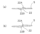
- FIG. 7 two types of springs are shown.
- FIG. 7A shows a state in which the front ends of the ring notches are bent in directions in which the ends are separated from each other.
- both ends of the notch are bent and formed, but it is also possible to bend only one side.
- FIG. 7B shows the ring formed by bending the entire ring so that the ends of the cutout portions of the ring are separated from each other.
- valve body modified by a valve body is shown in FIG. In the valve body shown in FIG. 8, only a part of the outer peripheral portion protrudes outward to form a spring locking portion 3B.
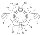
- the second embodiment is a developed version of the modification of the first embodiment described with reference to FIGS. 6 and 7, and a valve body holding portion is provided on one end side of the spring and is installed near the nozzle on the other end side. A support portion is provided.
- a spring 30 is installed on the nozzle end surface 6 ⁇ / b> A side of the valve body 3.
- the valve body 3 is urged only by the tip portion of the spring S, but the spring 30 of the second embodiment is operated by the valve body holding portion 31. Most of the three are energized.
- the spring 30 is formed by bending a wire-like spring material in layers, and a valve body holding portion 31 that holds the valve body 3 and the vicinity of the outlet of the nozzle 6. It consists of the support part 32 installed in.
- the valve body holding part 31 holds the valve body 3 by bending a wire spring material so as to cover the upper surface and the lower surface of the valve body 3 along the outer periphery of the disc-shaped valve body 3.
- the valve body holding portion 31 is installed on the outer peripheral side of the valve body 3 where it comes into contact with the nozzle 6. When the sprinkler head B is assembled, the valve body holding portion 31 is sandwiched between the valve body 3 and the nozzle 6. So that there is no interference.
- valve body holding portion 31 indicated by a broken line in FIG. 11A is a portion disposed on the surface of the valve body 3 on the nozzle 6 side, and an annular protrusion indicated by a two-dot chain line in FIG.
- the broken line portion is arranged outside the outer peripheral diameter of the portion 33.
- the support portion 32 is bent into a rectangular shape, and the inside is inserted and installed in an annular protrusion 33 at the outlet end of the nozzle 6 formed to protrude from the vicinity of the base of the frame 7 to the boss 8 side.
- the support portion 32 is a rectangular shape, but is not limited thereto, and may be formed in a circular shape. Further, it is possible to form the support portion 32 in a spiral manner like a coil spring, and the urging force of the spring 30 can be increased. More specifically, a biasing force in the water discharge direction of the nozzle 6 is obtained by the support portion 32 laminated in a spiral shape, and a biasing force in a direction inclined from the shaft 36 of the nozzle 6 is obtained by the connecting portion 34 described later.
- the spring 30 is biased obliquely upward.
- the support portion 32 is pulled out of the annular projection 33 of the nozzle 6 by the action of the spring 30, and the valve body 3 and the spring 30 can be released to the outside of the sprinkler head B.
- a connecting portion 34 is provided between the valve body holding portion 31 and the support portion 32. In normal times (a state before the sprinkler head B is activated), as shown in FIG. 10, the connecting portion 34 is pressed and bent by the thermal decomposition portion 4 incorporated between the valve body 3 and the impress screw 21. Yes.
- the connecting part 34 returns to the original linear shape as shown in FIG. 6 is held in an inclined state from the shaft 36. As the length of the connecting portion 34 is increased, the distance that the valve body 3 is separated from the nozzle 6 when the sprinkler head B is operated can be increased.
- the angle between the valve body holding part 31 and the support part 32 is set to a predetermined angle ⁇ .
- This angle ⁇ is an interval of 15 ° to 50 ° when the spring 30 is unloaded, and more preferably 20 ° to 40 °.
- the valve body 3 can be discharged to the outside of the sprinkler head by the water discharged from the nozzle 6. If the valve body holding portion 31 and the support portion 32 are held in parallel positions, the valve body 3 is scattered in the direction of the boss 8 by the water discharged from the nozzle 6 and is moored at the peripheral portion of the deflector 2. There is a fear.
- the support portion 32 is provided with an engagement portion 37 that can be engaged with the main body 1.
- the engaging portion 37 is formed at the end of the support portion 32 and engages with the inside of the recess 6 ⁇ / b> C formed near the nozzle 6 of the main body 1. Thereby, rotation of the spring 30 can be prevented and the biasing position of the spring 30 can be maintained.
- the engaging portion 37 When the engaging portion 37 is formed in the vicinity of the connecting portion 34, the engaging portion 37 is engaged with the recess 6 formed in the middle of the pair of frames 7, 7, and when the sprinkler head B is operated, the valve body 3 is engaged.
- the shaft 35 can be prevented from being directed in the direction of the frame 7. Thereby, the valve body 3 can avoid colliding with the flame
- the spring 30 of the second embodiment is larger than the spring S of the first embodiment because the most part of the valve body 3 is biased by the valve body holding portion 31, and the biasing force of the spring 30 is The amount of displacement is larger than that of the spring S of the first embodiment. More specifically, the spring S of the first embodiment biases only a part of the outer peripheral portion of the valve body 3 by the spring portion S3, but the spring 30 of the second embodiment is the outer peripheral portion of the valve body 3. Is held by the spring 30, In the state after the operation of the sprinkler head B (FIG. 11B), the displacement amount of the valve body 3 is also large. However, in the state incorporated in the sprinkler head B (FIG.
- the overall size of the spring 30 is substantially the same as that of the spring S of the first embodiment, and the installation position of the spring 30 is the same as that of the spring S of the first embodiment. Similarly, it is installed near the nozzle outlet end.
- This embodiment has the merit that the installation space of the spring 30 can be stored in a compact manner while increasing the amount of displacement of the valve body 3 by the spring 30.
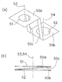
- the spring 40 shown in FIG. 12 has a two-fold plate spring shape, and a concave portion 41 is provided as a valve body holding portion on one piece 40a, and an outlet end of the nozzle 6 is provided as a support portion on the other piece 40b. A hole 42 that can be inserted into the annular protrusion 33 is formed.
- the recess 41 has a circular shape, and its inner diameter is slightly larger than the outer diameter of the valve body 3.
- An inner flange 41a is formed in the recess 41, and the outer peripheral portion of the valve body 3 is locked to the inner flange 41a.
- the outlet end of the nozzle 6 is in contact with the valve body 3 inside the inner flange 41a, and the inner flange 41a is sandwiched between the valve body 3 and the nozzle 6 so as not to interfere.
- An intermediate portion between the piece 40a and the piece 40b is a bent portion 43, which corresponds to the connecting portion 34 of the second embodiment.
- the bent portion 43 maintains the angle between the piece 40a and the piece 40b at a predetermined angle when the spring 40 is in an unloaded state. This angle is an interval of 15 ° to 50 ° in an unloaded state, and more preferably 20 ° to 40 °.
- the shaft 44 of the valve body 3 is inclined with respect to the shaft 45 of the hole 42, so that the water discharged from the nozzle 6 moves the valve body 3 to the outside of the sprinkler head. Can be released. Since the hole 42 is inserted into the annular protrusion 33 of the nozzle 6, the shaft 45 of the hole 24 is coaxial with the shaft 36 of the nozzle 6.
- a U-shaped notch 46 is formed at the edge of the recess 41, and a claw portion 47 formed between the notch 46 and the recess 41 is installed.
- the claw portion 47 is bent inside the concave portion 41 after the valve body 3 is accommodated in the concave portion 41, the claw portion 47 becomes a state indicated by a dotted line, and the valve body 3 is held so as to cover the upper surface and the lower surface of the valve body 3.
- the valve body 3 can be fixedly installed on the spring 40.
- FIG. 13 A modification of the second embodiment different from the above will be described.
- the spring 50 shown in FIG. 13 has a three-fold leaf spring shape, and a hole 51 is provided as a valve body holding portion in one piece 50a, and an outlet end of the nozzle 6 is provided as a support portion in the other piece 50b. A hole 52 that can be inserted into the annular protrusion 33 is formed. A connecting portion 50c is provided between the pieces 50a and 50b.
- the hole 51 is circular, and the inner diameter is smaller than the outer diameter of the valve body 3 and larger than the outer diameter of the outlet end of the nozzle 6. During normal times, the outer peripheral portion of the valve body 3 is pressed against the outlet end of the nozzle 6 in contact with the peripheral portion of the hole 51.
- the spring 50 urges the outer peripheral portion of the valve body 3.
- the configuration of the hole 51 can be replaced with the concave portion 41 similar to that of the first modification.
- the connecting portion 50c has an action of separating the shaft 53 of the hole 51 and the shaft 54 of the hole 52 at a predetermined interval when the spring 50 is in an unloaded state.
- the connecting portion 50c In normal times (the state before the sprinkler head operates), the connecting portion 50c is folded between the pieces 50a and 50b, and the shafts 53 and 54 are coaxial.
- the holes 51 and 52 are connected.
- the coaxial state is released and the respective axes are separated by a gap.
- the spring 50 is activated when the sprinkler head is operated.
- the piece 50a holding the valve body 3 is rotated about the piece 50b as a fulcrum by the restoring force of the spring 50 and the weight of the valve body 3, and the spring 50 and the valve body 3 are released to the outside of the sprinkler head. Can do.
Landscapes
- Health & Medical Sciences (AREA)
- Public Health (AREA)
- Business, Economics & Management (AREA)
- Emergency Management (AREA)
- Fire-Extinguishing By Fire Departments, And Fire-Extinguishing Equipment And Control Thereof (AREA)
Priority Applications (2)
| Application Number | Priority Date | Filing Date | Title |
|---|---|---|---|
| KR1020147014181A KR101926695B1 (ko) | 2011-12-01 | 2012-01-12 | 스프링클러 헤드 |
| TW101112026A TW201328748A (zh) | 2012-01-12 | 2012-04-05 | 灑水頭 |
Applications Claiming Priority (2)
| Application Number | Priority Date | Filing Date | Title |
|---|---|---|---|
| JP2011263202 | 2011-12-01 | ||
| JP2011-263202 | 2011-12-01 |
Publications (1)
| Publication Number | Publication Date |
|---|---|
| WO2013105241A1 true WO2013105241A1 (fr) | 2013-07-18 |
Family
ID=48781213
Family Applications (1)
| Application Number | Title | Priority Date | Filing Date |
|---|---|---|---|
| PCT/JP2012/050427 Ceased WO2013105241A1 (fr) | 2011-12-01 | 2012-01-12 | Tête d'arrosage |
Country Status (3)
| Country | Link |
|---|---|
| JP (2) | JPWO2013105241A1 (fr) |
| KR (1) | KR101926695B1 (fr) |
| WO (1) | WO2013105241A1 (fr) |
Cited By (2)
| Publication number | Priority date | Publication date | Assignee | Title |
|---|---|---|---|---|
| WO2019123711A1 (fr) * | 2017-12-20 | 2019-06-27 | 千住スプリンクラー株式会社 | Tête de gicleur |
| US11324980B2 (en) | 2018-02-05 | 2022-05-10 | Senju Sprinkler Co., Ltd. | Sprinkler head |
Families Citing this family (2)
| Publication number | Priority date | Publication date | Assignee | Title |
|---|---|---|---|---|
| KR101914958B1 (ko) * | 2017-02-28 | 2018-11-08 | 주식회사 파라텍 | 스프링클러 헤드 |
| KR20210108035A (ko) * | 2020-02-25 | 2021-09-02 | 정인진 | 스프링클러 합금퓨즈 |
Citations (3)
| Publication number | Priority date | Publication date | Assignee | Title |
|---|---|---|---|---|
| WO2000061238A1 (fr) * | 1999-04-09 | 2000-10-19 | Gengo Matsuoka | Systeme de crepine de type humide |
| JP2008125656A (ja) * | 2006-11-17 | 2008-06-05 | Senju Sprinkler Kk | フラッシュ型スプリンクラーヘッド |
| JP2011007879A (ja) * | 2009-06-23 | 2011-01-13 | Howa Mach Ltd | 内層基板用露光装置及び基板とマスクの剥離方法 |
Family Cites Families (2)
| Publication number | Priority date | Publication date | Assignee | Title |
|---|---|---|---|---|
| CH597921A5 (fr) * | 1976-01-30 | 1978-04-14 | Jomos Sprinkler Material Ag | |
| US5257827A (en) * | 1990-07-16 | 1993-11-02 | Senju Sprinkler Company Limited | Sprinkler head |
-
2012
- 2012-01-12 KR KR1020147014181A patent/KR101926695B1/ko active Active
- 2012-01-12 JP JP2013553141A patent/JPWO2013105241A1/ja active Pending
- 2012-01-12 WO PCT/JP2012/050427 patent/WO2013105241A1/fr not_active Ceased
-
2014
- 2014-12-18 JP JP2014006706U patent/JP3196269U/ja not_active Expired - Fee Related
Patent Citations (3)
| Publication number | Priority date | Publication date | Assignee | Title |
|---|---|---|---|---|
| WO2000061238A1 (fr) * | 1999-04-09 | 2000-10-19 | Gengo Matsuoka | Systeme de crepine de type humide |
| JP2008125656A (ja) * | 2006-11-17 | 2008-06-05 | Senju Sprinkler Kk | フラッシュ型スプリンクラーヘッド |
| JP2011007879A (ja) * | 2009-06-23 | 2011-01-13 | Howa Mach Ltd | 内層基板用露光装置及び基板とマスクの剥離方法 |
Cited By (3)
| Publication number | Priority date | Publication date | Assignee | Title |
|---|---|---|---|---|
| WO2019123711A1 (fr) * | 2017-12-20 | 2019-06-27 | 千住スプリンクラー株式会社 | Tête de gicleur |
| JPWO2019123711A1 (ja) * | 2017-12-20 | 2020-12-10 | 千住スプリンクラー株式会社 | スプリンクラーヘッド |
| US11324980B2 (en) | 2018-02-05 | 2022-05-10 | Senju Sprinkler Co., Ltd. | Sprinkler head |
Also Published As
| Publication number | Publication date |
|---|---|
| JPWO2013105241A1 (ja) | 2015-05-11 |
| JP3196269U (ja) | 2015-02-26 |
| KR20140106521A (ko) | 2014-09-03 |
| KR101926695B1 (ko) | 2018-12-07 |
Similar Documents
| Publication | Publication Date | Title |
|---|---|---|
| JP3196269U (ja) | スプリンクラーヘッド | |
| US9278240B2 (en) | Self-aligning cover spring for a concealed sprinkler | |
| JP3645857B2 (ja) | 消火器 | |
| CN102802736B (zh) | 喷水头 | |
| JP6138214B2 (ja) | スプリンクラヘッド | |
| US8474545B2 (en) | Sprinkler head | |
| CN102596332B (zh) | 导流装置托架 | |
| CN1141996C (zh) | 灭火装置 | |
| US20080087446A1 (en) | Self-activated fire extinguisher | |
| US20080115948A1 (en) | Sprinkler Head | |
| JP7229561B2 (ja) | スプリンクラーヘッド | |
| JP7092545B2 (ja) | スプリンクラーヘッド | |
| US20170312561A1 (en) | Fire prevention sprinkler with wrench boss detent and clip, and method of manufacturing same | |
| WO2018179615A1 (fr) | Tête de gicleur | |
| JP2001061988A (ja) | スプリンクラヘッド | |
| KR102307367B1 (ko) | 자동소화설비의 소화기 기동장치 | |
| US9987510B2 (en) | Fire protection sprinkler trigger assembly | |
| JP2013240414A (ja) | スプリンクラーヘッド | |
| JP2014076241A (ja) | スプリンクラーヘッド | |
| KR101804301B1 (ko) | 스프링클러 헤드의 감열장치 | |
| TW201328748A (zh) | 灑水頭 | |
| JP2008086394A (ja) | スプリンクラーヘッドカバー | |
| JP2014014583A (ja) | スプリンクラーヘッドカバー | |
| KR200232397Y1 (ko) | 스프링 클러 헤드 | |
| JP2008125656A (ja) | フラッシュ型スプリンクラーヘッド |
Legal Events
| Date | Code | Title | Description |
|---|---|---|---|
| 121 | Ep: the epo has been informed by wipo that ep was designated in this application |
Ref document number: 12865328 Country of ref document: EP Kind code of ref document: A1 |
|
| ENP | Entry into the national phase |
Ref document number: 2013553141 Country of ref document: JP Kind code of ref document: A |
|
| ENP | Entry into the national phase |
Ref document number: 20147014181 Country of ref document: KR Kind code of ref document: A |
|
| NENP | Non-entry into the national phase |
Ref country code: DE |
|
| 122 | Ep: pct application non-entry in european phase |
Ref document number: 12865328 Country of ref document: EP Kind code of ref document: A1 |