WO2013111198A1 - 塩素バイパス装置 - Google Patents
塩素バイパス装置 Download PDFInfo
- Publication number
- WO2013111198A1 WO2013111198A1 PCT/JP2012/002278 JP2012002278W WO2013111198A1 WO 2013111198 A1 WO2013111198 A1 WO 2013111198A1 JP 2012002278 W JP2012002278 W JP 2012002278W WO 2013111198 A1 WO2013111198 A1 WO 2013111198A1
- Authority
- WO
- WIPO (PCT)
- Prior art keywords
- pipe
- cooling
- cooling air
- exhaust gas
- extraction
- Prior art date
- Legal status (The legal status is an assumption and is not a legal conclusion. Google has not performed a legal analysis and makes no representation as to the accuracy of the status listed.)
- Ceased
Links
Images



Classifications
-
- F—MECHANICAL ENGINEERING; LIGHTING; HEATING; WEAPONS; BLASTING
- F27—FURNACES; KILNS; OVENS; RETORTS
- F27D—DETAILS OR ACCESSORIES OF FURNACES, KILNS, OVENS OR RETORTS, IN SO FAR AS THEY ARE OF KINDS OCCURRING IN MORE THAN ONE KIND OF FURNACE
- F27D17/00—Arrangements for using waste heat; Arrangements for using, or disposing of, waste gases
- F27D17/20—Arrangements for treatment or cleaning of waste gases
- F27D17/22—Arrangements for treatment or cleaning of waste gases for removing solid constituents
-
- B—PERFORMING OPERATIONS; TRANSPORTING
- B01—PHYSICAL OR CHEMICAL PROCESSES OR APPARATUS IN GENERAL
- B01D—SEPARATION
- B01D53/00—Separation of gases or vapours; Recovering vapours of volatile solvents from gases; Chemical or biological purification of waste gases, e.g. engine exhaust gases, smoke, fumes, flue gases, aerosols
- B01D53/34—Chemical or biological purification of waste gases
- B01D53/46—Removing components of defined structure
- B01D53/68—Halogens or halogen compounds
-
- C—CHEMISTRY; METALLURGY
- C04—CEMENTS; CONCRETE; ARTIFICIAL STONE; CERAMICS; REFRACTORIES
- C04B—LIME, MAGNESIA; SLAG; CEMENTS; COMPOSITIONS THEREOF, e.g. MORTARS, CONCRETE OR LIKE BUILDING MATERIALS; ARTIFICIAL STONE; CERAMICS; REFRACTORIES; TREATMENT OF NATURAL STONE
- C04B7/00—Hydraulic cements
- C04B7/36—Manufacture of hydraulic cements in general
- C04B7/60—Methods for eliminating alkali metals or compounds thereof, e.g. from the raw materials or during the burning process; methods for eliminating other harmful components
-
- F—MECHANICAL ENGINEERING; LIGHTING; HEATING; WEAPONS; BLASTING
- F27—FURNACES; KILNS; OVENS; RETORTS
- F27B—FURNACES, KILNS, OVENS OR RETORTS IN GENERAL; OPEN SINTERING OR LIKE APPARATUS
- F27B15/00—Fluidised-bed furnaces; Other furnaces using or treating finely-divided materials in dispersion
- F27B15/003—Cyclones or chain of cyclones
-
- F—MECHANICAL ENGINEERING; LIGHTING; HEATING; WEAPONS; BLASTING
- F27—FURNACES; KILNS; OVENS; RETORTS
- F27B—FURNACES, KILNS, OVENS OR RETORTS IN GENERAL; OPEN SINTERING OR LIKE APPARATUS
- F27B7/00—Rotary-drum furnaces, i.e. horizontal or slightly inclined
- F27B7/20—Details, accessories or equipment specially adapted for rotary-drum furnaces
-
- F—MECHANICAL ENGINEERING; LIGHTING; HEATING; WEAPONS; BLASTING
- F27—FURNACES; KILNS; OVENS; RETORTS
- F27D—DETAILS OR ACCESSORIES OF FURNACES, KILNS, OVENS OR RETORTS, IN SO FAR AS THEY ARE OF KINDS OCCURRING IN MORE THAN ONE KIND OF FURNACE
- F27D17/00—Arrangements for using waste heat; Arrangements for using, or disposing of, waste gases
- F27D17/30—Arrangements for extraction or collection of waste gases; Hoods therefor
-
- F—MECHANICAL ENGINEERING; LIGHTING; HEATING; WEAPONS; BLASTING
- F27—FURNACES; KILNS; OVENS; RETORTS
- F27D—DETAILS OR ACCESSORIES OF FURNACES, KILNS, OVENS OR RETORTS, IN SO FAR AS THEY ARE OF KINDS OCCURRING IN MORE THAN ONE KIND OF FURNACE
- F27D7/00—Forming, maintaining or circulating atmospheres in heating chambers
- F27D7/02—Supplying steam, vapour, gases or liquids
-
- B—PERFORMING OPERATIONS; TRANSPORTING
- B01—PHYSICAL OR CHEMICAL PROCESSES OR APPARATUS IN GENERAL
- B01D—SEPARATION
- B01D2257/00—Components to be removed
- B01D2257/20—Halogens or halogen compounds
- B01D2257/202—Single element halogens
- B01D2257/2025—Chlorine
-
- B—PERFORMING OPERATIONS; TRANSPORTING
- B01—PHYSICAL OR CHEMICAL PROCESSES OR APPARATUS IN GENERAL
- B01D—SEPARATION
- B01D45/00—Separating dispersed particles from gases or vapours by gravity, inertia, or centrifugal forces
- B01D45/12—Separating dispersed particles from gases or vapours by gravity, inertia, or centrifugal forces by centrifugal forces
-
- F—MECHANICAL ENGINEERING; LIGHTING; HEATING; WEAPONS; BLASTING
- F27—FURNACES; KILNS; OVENS; RETORTS
- F27D—DETAILS OR ACCESSORIES OF FURNACES, KILNS, OVENS OR RETORTS, IN SO FAR AS THEY ARE OF KINDS OCCURRING IN MORE THAN ONE KIND OF FURNACE
- F27D17/00—Arrangements for using waste heat; Arrangements for using, or disposing of, waste gases
- F27D17/20—Arrangements for treatment or cleaning of waste gases
- F27D17/22—Arrangements for treatment or cleaning of waste gases for removing solid constituents
- F27D17/25—Arrangements for treatment or cleaning of waste gases for removing solid constituents using cyclones
Definitions
- the present invention relates to a chlorine bypass device provided in a cement manufacturing facility or the like for removing chlorine from the system of the facility.
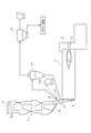
- FIG. 10 shows a typical conventional cement manufacturing facility.
- the cement production facility includes a rotary kiln 1 for firing cement raw material, a preheater 4 including a plurality of cyclones provided in a kiln bottom 2 of the rotary kiln 1, and a cement raw material from a cyclone at the lowest stage of the preheater 4 Is provided to the kiln bottom 2 of the rotary kiln 1, the exhaust line 6 connected to the uppermost cyclone for discharging combustion exhaust gas, and the main for heating the inside of the rotary kiln 1 provided in front of the kiln 3.
- the burner 7 is generally configured.
- the cement raw material supplied to the preheater 4 is preheated by exchanging heat with the high-temperature exhaust gas from the rotary kiln 1 that rises from below as it sequentially falls into the lower cyclone.
- the rotary kiln 1 introduced into the kiln bottom 2 of the rotary kiln 1 through the lowermost chute 5 is baked in the process of being sent from the kiln bottom 2 side to the kiln front 3 to the cement clinker. Become.
- the chlorine content contained in the cement raw material and the chlorine content contained in the waste material such as plastic input as part of the fuel are in a high temperature (about 1400 ° C.) atmosphere in the rotary kiln 1. It volatilizes mainly as alkali chlorides such as KCl and NaCl and moves into the exhaust gas. And when this exhaust gas is exhausted from the kiln bottom part 2 of the rotary kiln 1 to the preheater 4 side and rises sequentially from the lower part to the upper cyclone, it is cooled by preheating the cement raw material, and is contained in the exhaust gas. The chlorine content is transferred to the cement raw material side again.
- the chlorine content circulates in the system composed of the rotary kiln 1 and the preheater 4, so that the internal chlorine concentration gradually increases due to the chlorine content newly introduced into the system from the fuel or cement raw material, As a result, the cyclone of the preheater 4 is obstructed and operation is hindered.
- the cement production facility is provided with a chlorine bypass device for removing chlorine in the system.
- This chlorine bypass device is connected to an exhaust gas pipe 8 from the kiln bottom 2 to extract an extraction pipe 9 for extracting a part of the exhaust gas, and cooling air supplied from the blower 10a to the exhaust gas extracted by the extraction pipe 9
- a cooling pipe 10 that mixes and cools, a cyclone 11 that separates and removes the cement raw material from the exhaust gas in the extraction pipe 9, and a bag filter that collects chloride dust contained in the exhaust gas that has passed through the cyclone 11. Collecting device) 12.
- the chlorine bypass device a part of the exhaust gas discharged from the rotary kiln 1 through the exhaust gas pipe 8 is extracted by the extraction pipe 9 periodically or continuously, and cooled by the cooling pipe 10, thereby exhaust gas.
- the chloride gas contained therein is condensed to precipitate chloride dust, and then, in the cyclone 11, after the dust of the cement raw material having a large particle size in the exhaust gas is selectively removed, the particle size accompanying the exhaust gas is small.
- the cooling pipe 10 that mixes the cooling air with the exhaust gas extracted by the extraction pipe 9 reduces the exhaust gas temperature to a temperature that can be supplied to the bag filter 12 in the subsequent stage.
- the chloride gas contained in the exhaust gas is condensed to form chloride dust.
- cooling pipe 10 a double pipe structure as shown in FIG. 11 is generally used.
- the cooling pipe 10 is connected to the outer pipe 13 whose one end is connected to the exhaust gas pipe 8 and whose other end is closed, and to the closed end of the outer pipe 13 in a direction perpendicular to the outer pipe 13.
- the bleeder tube 9 is coaxially inserted from the closed end of the outer tube 13 into the inside of the outer tube 13.
- the cooling pipe 10 a part of the exhaust gas flowing into the outer pipe 13 from the exhaust pipe 8 and the space between the outer pipe 13 and the extraction pipe 9 are supplied from the supply pipe 14 in the outer pipe 13.
- the cooling air that flows down is mixed and cooled, and sent from the extraction pipe 9 to the cyclone 11.
- the cooling means found in the following Patent Documents 1 to 3 have substantially the same configuration.
- JP 2007-105687 A Japanese Patent No. 3125248 Japanese Patent Laid-Open No. 02-116649
- the coating C 2 tends to adhere to the periphery of the connection portion between the outer pipe 13 and the exhaust pipe 8. Therefore, the cooling air, by lowering to the portion, the portion covering as air curtain by the cooling air, it is effective to prevent the adhesion of the coating C 2.
- the cooling air descending distance changes due to fluctuations in the extraction rate. Therefore, if the cooling air descending distance is extended to the vicinity of the inlet of the outer tube 13, the cooling air descending distance is increased at a high extraction rate. There was a problem that cooling air was blown into the exhaust gas pipe 8 and as a result, heat loss in the system increased.
- the present invention has been made in view of the above circumstances, and can prevent the coating from adhering to the inner wall of the bleed pipe, and even if the bleed rate of the exhaust gas changes, the exhaust gas is always bleed. It is an object of the present invention to provide a chlorine bypass device that can rapidly cool by mixing cooling air with high efficiency, and thus can generate fine chloride dust and increase recovery efficiency.
- an invention includes an extraction pipe connected to an exhaust gas pipe for extracting a part of exhaust gas containing chloride, and an exhaust gas for cooling the exhaust gas in the extraction pipe.
- the chlorine bypass device comprising a cooling means for supplying and a collecting device for collecting chloride dust contained in the exhaust gas extracted by the extraction pipe
- the cooling means flows cooling air into the extraction pipe
- a blower for supplying cooling air to the cooling pipe
- the cooling pipe includes a cylindrical inner pipe that surrounds the outer wall of the extraction pipe with a gap between the inner pipe and the inner pipe.
- a cooling air duct from the blower is connected to the swirl portion so as to introduce the cooling air in a circumferential direction of the swirl portion.
- an inflow port through which the cooling air of the introduction portion flows into the bleed pipe is formed on the outer wall of the bleed tube over the entire circumference, so that the swirl portion reaches the inflow port through the introduction portion.
- a flow path for the cooling gas is formed.
- the invention according to a second aspect of the present invention is the invention according to the first aspect, wherein the inner tube, the outer tube, and the reduced diameter tube are arranged with their respective axes aligned with the axis of the extraction tube.
- the average flow velocity of the cooling air in the longitudinal section in the axial direction of the flow passage of the cooling air is V S
- the average flow velocity of the extraction gas in the transverse section orthogonal to the axial direction of the extraction pipe is V
- the cooling pipe is formed to satisfy 1.0 ⁇ V S / V C.
- the invention according to a third aspect of the present invention is the invention according to the first aspect or the second aspect, wherein the inner tube, the outer tube, and the reduced diameter tube have their axes aligned with the bleed tube.
- An average flow velocity of the cooling air in the longitudinal cross section in the axial direction of the flow passage of the cooling air is V S (m / s)
- V M (m / s) the cooling pipe is formed so that (V S 2 + V M 2 ) 1/2 ⁇ 90. It is characterized by being.
- the exhaust gas pipe is discharged from a kiln for firing cement raw material in a cement production facility. It is an exhaust gas pipe that sends exhaust gas to a preheater that preheats the cement raw material.
- the swirling part of the cooling pipe into which the cooling air is introduced has an annular shape surrounding the exhaust gas extraction pipe through a gap. Therefore, the extraction pipe of the exhaust gas is not cooled by the cooling air flowing through the swirling portion, and therefore it is possible to reliably prevent the coating from adhering to the inner wall of the extraction pipe.
- the cooling air introduced in the circumferential direction of the swirling part via the cooling air duct is supplied to the introducing part from the swirling part while swirling over the entire circumference, and the outer wall of the extraction pipe From the inlet formed over the entire circumference into the extraction pipe. For this reason, in the extraction pipe, the extracted exhaust gas and the cooling air are stirred and mixed while vigorously swirling. Therefore, the exhaust gas is rapidly cooled by the cooling air to generate fine chloride dust. it can.
- the chlorine bypass device is used to remove chlorine from the exhaust gas discharged from the kiln that burns the cement raw material in the cement production facility.
- the temperature of the exhaust gas extracted from the exhaust pipe is about 1200 ° C.
- the length of the mixed cooling zone in which the exhaust gas is cooled by the cooling air while flowing through the extraction pipe and lowered to 800 ° C. is the gas cooling distance, more precisely, the temperature of 1200 ° C. in the cross section of the extraction pipe. Is defined as the length dimension between the position farthest from the exhaust pipe that can be detected and the position farthest from the exhaust pipe that can detect a temperature of 800 ° C. in the cross section, the shorter the gas cooling distance, the higher the efficiency. This means that rapid cooling by mixing is performed.
- V S the average flow velocity of the cooling air in the longitudinal section in the axial direction of the flow passage of the cooling air, and the axis of the extraction pipe.
- the average flow velocity of the extracted gas in cross section perpendicular to the direction when a V C was to verify the relationship between V S / V C and the gas cooling distance in the case of changing the size specifications of the cooling pipe.
- the gas cooling distance is set to a desired chloride by rapid cooling. The knowledge that it becomes 1200 mm or less from which the refinement
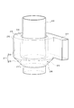
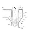
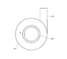
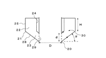
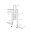
- FIG. 1 and 2 show a bleed pipe and a cooling pipe for exhaust gas extracted from the bleed pipe in one embodiment of the chlorine bypass device according to the present invention.
- the other components are shown in FIG. Since they are the same as those described above, the description thereof will be simplified using the same reference numerals.
- reference numeral 20 in the figure is an extraction pipe whose lower end is connected to the exhaust gas pipe 8 from the kiln bottom 2 of the rotary kiln 1 and extracts a part of the exhaust gas
- reference numeral 21 is the extraction pipe 20.
- This is a cooling pipe 21 for rapidly cooling the exhaust gas extracted by the cooling air sent from the blower 10a.
- the cooling pipe 21 is generally configured by a turning part 22 and an introduction part 23 that is integrally formed with the end part 22a on the exhaust gas pipe 8 side of the turning part 22 and connected to the extraction pipe 20.
- the swivel unit 22 includes a cylindrical inner tube 24, a cylindrical outer tube 25 arranged with its axis aligned with the outer side of the inner tube 24, and ends of the inner tube 24 and the outer tube 25. It is formed in an annular shape by the top plate 26 to be closed.
- the swivel unit 22 is disposed so that the inner tube 24 is aligned with the axis of the extraction tube 20 and surrounds the outer wall of the extraction tube 20 with a predetermined interval. Further, a space between the lower end portion of the inner pipe 24 in the drawing and the extraction pipe 20 is closed by a bottom plate 24a.
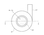
- a cooling air duct 27 from the blower 10 a is connected in the tangential direction of the inner tube 24 and the outer tube 25 so as to introduce the cooling air in the circumferential direction of the swivel unit 22.
- the introduction portion 23 is a conical tube (reduced diameter tube) in which the diameter is gradually reduced from the end portion 22a of the outer tube 25 of the swivel unit 22 toward the exhaust gas tube 8 and the tip is joined to the outer wall of the extraction tube 20. ) 28 is defined so as to communicate with the swivel unit 22.
- this introduction portion 23 the outer wall portion of the extraction tube 20 facing the conical tube 28 is opened, so that an inlet 29 for cooling air is formed over the entire circumference.
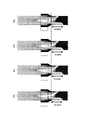
- a cooling air flow path 30 (see FIGS. 4A to 6) is formed in the cooling pipe 21 from the swivel portion 22 through the introduction portion 23 to the inlet 29.
- the dimensions of the cooling pipe 21 are the average flow velocity of the extraction gas in the cross section orthogonal to the axial direction of the extraction pipe 20, that is, the cross section is the front and back direction of the drawing sheet.
- the average flow velocity obtained by dividing the flow rate Q C (Nm 3 / s) of the bleed gas passing through 1 by the area A C (m 2 ) of the cross section is V C (m / s).
- the average flow velocity of the cooling air in the longitudinal section of the cooling air passage 30 of the cooling pipe 21 in the axial direction that is, the cooling passing through the longitudinal section of the passage 30 indicated by the oblique lines in the figure in the front and back direction of the drawing.
- the dimensions of the cooling pipe 21 are the average flow velocity of the cooling air in the narrowest portion 30a in the longitudinal section of the cooling air flow path 30 in the axial direction, that is, The flow rate of the cooling air flowing through the narrowest part 30a from the revolving part 22 side to the introducing part 23 side is divided by the area A M (m 2 ) in the circumferential direction forming the side surface of the truncated cone of the narrowest part 30a.
- the average flow velocity when the V M (m / s) the synthesis rate of V S and V M [(V S 2 + V M 2) 1/2] (m / s) is (V S 2 + V M 2 ) 1/2 ⁇ 90, It is set to be.
- the swirling portion 22 of the cooling pipe 21 into which the cooling air is introduced has an exhaust pipe extraction pipe 20 through a gap between the swivel section 22 and the inner pipe 24. Therefore, the extraction pipe 20 is not cooled by the cooling air flowing through the swivel unit 22, thereby reliably preventing the coating from adhering to the inner wall of the extraction pipe 20. be able to.
- the cooling air introduced from the cooling air duct 27 in the circumferential direction of the swivel unit 22 is supplied to the introduction unit 23 that gradually reduces the diameter from the swivel unit 22 while swirling over the entire circumference. Then, the air flows into the extraction pipe 20 from an inlet 29 formed on the outer wall of the extraction pipe 20 over the entire circumference. For this reason, in the extraction pipe 20, the extracted exhaust gas and the cooling air are stirred and mixed while vigorously swirling. Therefore, the exhaust gas is rapidly cooled by the cooling air to generate fine chloride dust. Can do.
- the longitudinal dimension of the dimension of the cooling pipe 21 in the axial direction of the cooling air flow path 30 of the cooling pipe 21, where V C is the average flow velocity of the extraction gas in the cross section orthogonal to the axial direction of the extraction pipe 20. Is set so that 1.0 ⁇ V S / V C , where the average flow velocity of the cooling air is V S , the above-mentioned gas cooling distance is set to a desired chloride by rapid cooling. It can be set to 1200 mm or less so that the dust refinement effect can be obtained.
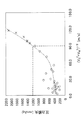
- the average flow velocity of the cooling air at the narrowest portion 30a of the channel 30 of the cooling air is taken as V M, (V S 2 + V M 2) 1/2 Since it is set so that ⁇ 90, the pressure loss of the cooling air in the cooling pipe 21 can be 1200 mmAq or less, and therefore there is no possibility that the air supply means such as a blower becomes excessive. .
- FIG. 3 shows the analysis result.
- the descending distance of the cooling air becomes substantially constant. It can be seen that the cooling air does not blow through the exhaust gas pipe regardless of the change in the exhaust gas extraction rate.
- a S (m 2 ) d 2 sin ⁇ ⁇ cos ⁇ + 2d ⁇ + d 2 (cos 3 ⁇ / sin ⁇ ) + 2d (H / tan ⁇ )
- the cooling air volume Q (Nm 3 / s)
- Table 1 is a chart showing the analysis results in the embodiment of the present invention.
- the inner diameter dimension D of the extraction pipe 20, the height dimension H of the swivel portion 22, and the height dimension in the axial direction of the inflow port 29 are as follows.
- d shows the results of the gas cooling distance and pressure loss calculated based on A S and A M when the specifications of the inclination angle ⁇ of the conical tube 28 are changed.
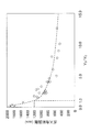
- FIG. 7 plots the analysis results of Table 1 with V S / V C as the horizontal axis and the gas cooling distance as the vertical axis
- FIG. 8 shows V S / V C ⁇ 15. This is an enlarged view of the 0 part.
- FIG. 9 the same analysis results in Table 1, a plot of (V S 2 + V M 2 ) 1/2 the horizontal axis, the pressure loss as the ordinate.
- the gas cooling distance can be reduced to a desired level of chloride dust by rapid cooling.
- the thickness can be made 1200 mm or less at which an effect is obtained.
- the conical tube 28 is used as the reduced diameter tube that defines the outer wall of the introduction portion 23 .
- the present invention is not limited to this.
- various A shape-reduced tube can be used. Even when other diameter-reduced tubes are used, it is possible to calculate the average flow velocities V S and V M by similarly obtaining the areas A S and A M by drawing.
- a plurality of cooling air ducts 27 connected to the cooling pipe 21 can be connected.
- Coaching can be prevented from adhering to the inner wall of the bleed pipe, and even if the bleed rate of the exhaust gas changes, cooling air can always be mixed with the evacuated exhaust gas with high efficiency for rapid cooling. Therefore, a chlorine bypass device that can generate fine chloride dust and increase the recovery efficiency can be provided.
Landscapes
- Engineering & Computer Science (AREA)
- Chemical & Material Sciences (AREA)
- Mechanical Engineering (AREA)
- General Engineering & Computer Science (AREA)
- Environmental & Geological Engineering (AREA)
- Ceramic Engineering (AREA)
- Health & Medical Sciences (AREA)
- Analytical Chemistry (AREA)
- Biomedical Technology (AREA)
- Dispersion Chemistry (AREA)
- Oil, Petroleum & Natural Gas (AREA)
- General Chemical & Material Sciences (AREA)
- Public Health (AREA)
- Toxicology (AREA)
- Chemical Kinetics & Catalysis (AREA)
- Materials Engineering (AREA)
- Structural Engineering (AREA)
- Organic Chemistry (AREA)
- Waste-Gas Treatment And Other Accessory Devices For Furnaces (AREA)
- Muffle Furnaces And Rotary Kilns (AREA)
- Treating Waste Gases (AREA)
- Processing Of Solid Wastes (AREA)
Priority Applications (4)
| Application Number | Priority Date | Filing Date | Title |
|---|---|---|---|
| KR1020147020095A KR101832550B1 (ko) | 2012-01-23 | 2012-04-02 | 염소 바이패스 장치 |
| EP12866659.1A EP2808311A4 (de) | 2012-01-23 | 2012-04-02 | Chlorbypassvorrichtung |
| CN201280067855.5A CN104066698B (zh) | 2012-01-23 | 2012-04-02 | 氯旁路装置 |
| US14/371,133 US9823020B2 (en) | 2012-01-23 | 2012-04-02 | Chlorine bypass device |
Applications Claiming Priority (2)
| Application Number | Priority Date | Filing Date | Title |
|---|---|---|---|
| JP2012010737A JP5051325B1 (ja) | 2012-01-23 | 2012-01-23 | 塩素バイパス装置 |
| JP2012-010737 | 2012-01-23 |
Publications (1)
| Publication Number | Publication Date |
|---|---|
| WO2013111198A1 true WO2013111198A1 (ja) | 2013-08-01 |
Family
ID=47189477
Family Applications (1)
| Application Number | Title | Priority Date | Filing Date |
|---|---|---|---|
| PCT/JP2012/002278 Ceased WO2013111198A1 (ja) | 2012-01-23 | 2012-04-02 | 塩素バイパス装置 |
Country Status (6)
| Country | Link |
|---|---|
| US (1) | US9823020B2 (de) |
| EP (1) | EP2808311A4 (de) |
| JP (1) | JP5051325B1 (de) |
| KR (1) | KR101832550B1 (de) |
| CN (1) | CN104066698B (de) |
| WO (1) | WO2013111198A1 (de) |
Families Citing this family (22)
| Publication number | Priority date | Publication date | Assignee | Title |
|---|---|---|---|---|
| DE102012110653B3 (de) * | 2012-11-07 | 2014-05-15 | Thyssenkrupp Resource Technologies Gmbh | Zementherstellungsanlage |
| DE102014116532A1 (de) * | 2014-11-12 | 2016-05-12 | Thyssenkrupp Ag | Verfahren zur Verminderung eines Schadstoffgehalts eines bei einer thermischen Behandlung eines Materials entstehenden oder genutzten Abgasstroms |
| ES2664830T3 (es) | 2015-07-09 | 2018-04-23 | Südbayerisches Portland-Zementwerk Gebr. Wiesböck & Co. GmbH | Procedimiento y aparato de producción de clinker de cemento |
| JP6919364B2 (ja) * | 2017-02-14 | 2021-08-18 | 宇部興産株式会社 | キルンガスの抽気装置及び抽気方法 |
| CN107175012A (zh) * | 2017-07-04 | 2017-09-19 | 合肥青鸾新能源科技有限公司 | 一种锂电池生产用石墨原料混合装置 |
| CN110465213B (zh) * | 2018-05-12 | 2022-07-12 | 中国石油化工股份有限公司 | 气体旋风混合器 |
| JP7481145B2 (ja) | 2020-03-31 | 2024-05-10 | Ube三菱セメント株式会社 | チャンバ、塩素バイパス設備、セメントクリンカ製造設備、及びセメントクリンカの製造方法 |
| JP7420627B2 (ja) * | 2020-03-31 | 2024-01-23 | Ube三菱セメント株式会社 | 冷却風導入装置、塩素バイパス設備、セメントクリンカ製造設備、及びセメントクリンカの製造方法 |
| MX2022012039A (es) | 2020-04-08 | 2022-10-27 | Thyssenkrupp Ind Solutions Ag | Procedimiento y dispositivo para la fabricacion de clinker. |
| IL297010B2 (en) | 2020-05-05 | 2025-10-01 | Thyssenkrupp Ind Solutions Ag | Cement production plant and cement clinker production process |
| CN111647151B (zh) * | 2020-06-10 | 2022-09-23 | 珠海麦得发生物科技股份有限公司 | 一种高效全自动二次纯化pha的工艺 |
| JP7556775B2 (ja) | 2020-12-23 | 2024-09-26 | Ube三菱セメント株式会社 | 塩素バイパス設備、セメントクリンカ製造装置、及びセメントクリンカの製造方法 |
| JP7594470B2 (ja) * | 2021-03-16 | 2024-12-04 | Ube三菱セメント株式会社 | 塩素バイパス設備及びその運転方法、セメントクリンカ製造装置、並びにセメントクリンカの製造方法 |
| JP7628861B2 (ja) | 2021-03-30 | 2025-02-12 | Ube三菱セメント株式会社 | 塩素バイパス設備、セメントクリンカ製造装置、セメントクリンカの製造方法、塩素バイパス設備の運転方法、および塩素含有廃棄物処理方法 |
| JP7670527B2 (ja) * | 2021-03-30 | 2025-04-30 | Ube三菱セメント株式会社 | 塩素バイパス設備、セメントクリンカ製造装置、セメントクリンカの製造方法、塩素バイパス設備の運転方法、および廃棄物処理方法 |
| JP7663394B2 (ja) | 2021-03-30 | 2025-04-16 | Ube三菱セメント株式会社 | 塩素バイパス設備、セメントクリンカ製造装置、セメントクリンカの製造方法、塩素バイパス設備の運転方法、および塩素含有廃棄物処理方法 |
| CN113237326A (zh) * | 2021-04-28 | 2021-08-10 | 安徽省泽乾冶金科技有限公司 | 一种回转窑余热利用装置 |
| KR102313703B1 (ko) | 2021-06-04 | 2021-10-19 | 쌍용씨앤이 주식회사 | 가연성 재활용 순환연료의 고온 연소가스와 시멘트 원료분해 가스 중 순환물질의 인출을 위한 인출 장치 |
| JP7386913B2 (ja) * | 2022-03-10 | 2023-11-27 | 太平洋セメント株式会社 | 燃焼ガス抽気プローブ及びその運転方法 |
| JP7343639B1 (ja) | 2022-03-10 | 2023-09-12 | 太平洋セメント株式会社 | 燃焼ガス抽気プローブ及びその運転方法 |
| WO2023171460A1 (ja) * | 2022-03-10 | 2023-09-14 | 太平洋セメント株式会社 | 燃焼ガス抽気プローブ及びその運転方法 |
| CN114993059A (zh) * | 2022-05-26 | 2022-09-02 | 中国中材国际工程股份有限公司 | 一种用于水泥熟料烧成系统的冷却系统及烟气冷却方法 |
Citations (4)
| Publication number | Priority date | Publication date | Assignee | Title |
|---|---|---|---|---|
| JPH02116649A (ja) | 1988-10-25 | 1990-05-01 | Tosoh Corp | セメント焼成設備のスケール付着防止方法、及び装置、並びにこれに用いるバイパス管 |
| JPH1135355A (ja) * | 1997-07-17 | 1999-02-09 | Chichibu Onoda Cement Corp | キルンバイパスにおける排ガス冷却方法及びその装置 |
| JP2007105687A (ja) | 2005-10-17 | 2007-04-26 | Sumitomo Osaka Cement Co Ltd | 排ガス抽気用プローブとそれを備えたセメント焼成設備及びセメント焼成設備における排ガス処理方法 |
| JP2008239413A (ja) * | 2007-03-28 | 2008-10-09 | Ube Ind Ltd | セメントキルン排ガスの抽気装置 |
Family Cites Families (12)
| Publication number | Priority date | Publication date | Assignee | Title |
|---|---|---|---|---|
| NL87758C (de) * | 1954-06-30 | |||
| US4004898A (en) * | 1976-01-30 | 1977-01-25 | Emtrol Corporation | Cyclone separator gas tube heat dissipator |
| JP3438489B2 (ja) * | 1995-10-24 | 2003-08-18 | 宇部興産株式会社 | 抽気セメントキルン排ガスの処理方法及び処理装置 |
| DK0808809T4 (da) * | 1995-12-11 | 2012-12-10 | Taiheiyo Cement Corp | Fremgangsmåde til behandling af ovnforbrændingsgas ved afledning af chlor og et apparat dertil |
| PT102392A (pt) * | 1999-12-13 | 2000-11-30 | Romualdo Luis Ribera Salcedo | Ciclones de recirculacao para despoeiramento e lavagem de gases |
| US7544224B2 (en) | 2003-08-05 | 2009-06-09 | Electrolux Home Care Products, Inc. | Cyclonic vacuum cleaner |
| US7357824B2 (en) * | 2003-11-19 | 2008-04-15 | Hakola Gordon R | Cyclone with in-situ replaceable liner mechanisms and methods for accomplishing same |
| US6997973B2 (en) * | 2003-12-02 | 2006-02-14 | Huber Engineered Woods Llc | Cyclone with plug prevention |
| JP2007105678A (ja) * | 2005-10-14 | 2007-04-26 | Spg Techno Kk | 弁構造を利用した軽重質油乳化燃料の生成方法とその装置 |
| US20070251386A1 (en) * | 2006-04-27 | 2007-11-01 | Sceptor Industries Inc. | Dry cyclone collection system |
| DK176904B1 (da) * | 2008-01-05 | 2010-04-12 | Smidth As F L | Indretning og fremgangsmåde til afkøling af ovnrøggas i et ovn-bypass |
| JP4435273B1 (ja) * | 2009-07-31 | 2010-03-17 | 電気化学工業株式会社 | セメントキルン排ガス抽気処理装置及びその運転方法 |
-
2012
- 2012-01-23 JP JP2012010737A patent/JP5051325B1/ja active Active
- 2012-04-02 KR KR1020147020095A patent/KR101832550B1/ko active Active
- 2012-04-02 CN CN201280067855.5A patent/CN104066698B/zh not_active Expired - Fee Related
- 2012-04-02 EP EP12866659.1A patent/EP2808311A4/de not_active Withdrawn
- 2012-04-02 US US14/371,133 patent/US9823020B2/en active Active
- 2012-04-02 WO PCT/JP2012/002278 patent/WO2013111198A1/ja not_active Ceased
Patent Citations (5)
| Publication number | Priority date | Publication date | Assignee | Title |
|---|---|---|---|---|
| JPH02116649A (ja) | 1988-10-25 | 1990-05-01 | Tosoh Corp | セメント焼成設備のスケール付着防止方法、及び装置、並びにこれに用いるバイパス管 |
| JPH1135355A (ja) * | 1997-07-17 | 1999-02-09 | Chichibu Onoda Cement Corp | キルンバイパスにおける排ガス冷却方法及びその装置 |
| JP3125248B2 (ja) | 1997-07-17 | 2001-01-15 | 太平洋セメント株式会社 | キルンバイパスにおける排ガス冷却方法及びその装置 |
| JP2007105687A (ja) | 2005-10-17 | 2007-04-26 | Sumitomo Osaka Cement Co Ltd | 排ガス抽気用プローブとそれを備えたセメント焼成設備及びセメント焼成設備における排ガス処理方法 |
| JP2008239413A (ja) * | 2007-03-28 | 2008-10-09 | Ube Ind Ltd | セメントキルン排ガスの抽気装置 |
Non-Patent Citations (1)
| Title |
|---|
| See also references of EP2808311A4 |
Also Published As
| Publication number | Publication date |
|---|---|
| JP5051325B1 (ja) | 2012-10-17 |
| CN104066698A (zh) | 2014-09-24 |
| EP2808311A1 (de) | 2014-12-03 |
| US20140366499A1 (en) | 2014-12-18 |
| CN104066698B (zh) | 2015-12-02 |
| JP2013147401A (ja) | 2013-08-01 |
| EP2808311A4 (de) | 2015-08-12 |
| KR20140112520A (ko) | 2014-09-23 |
| KR101832550B1 (ko) | 2018-04-04 |
| US9823020B2 (en) | 2017-11-21 |
Similar Documents
| Publication | Publication Date | Title |
|---|---|---|
| JP5051325B1 (ja) | 塩素バイパス装置 | |
| JP6344867B2 (ja) | セメント焼成装置 | |
| JP5407262B2 (ja) | セメント焼成設備の排ガス処理方法および処理システム | |
| JPS6352933B2 (de) | ||
| WO2014041919A1 (ja) | コークス乾式消火設備 | |
| JP2008239413A (ja) | セメントキルン排ガスの抽気装置 | |
| JP6631293B2 (ja) | 抽気装置及び抽気方法 | |
| US9724843B2 (en) | Cement production system | |
| US9890080B2 (en) | Cement plant | |
| JP5560469B2 (ja) | セメント製造装置 | |
| JP2010126411A (ja) | セメント焼成設備の排ガス処理方法および処理システム | |
| JP4926442B2 (ja) | 排ガス抽気用プローブとそれを備えたセメント焼成設備及びセメント焼成設備における排ガス処理方法 | |
| KR102313703B1 (ko) | 가연성 재활용 순환연료의 고온 연소가스와 시멘트 원료분해 가스 중 순환물질의 인출을 위한 인출 장치 | |
| JP7386913B2 (ja) | 燃焼ガス抽気プローブ及びその運転方法 | |
| JP2012201580A (ja) | 排ガスの冷却方法及び排ガスの冷却装置 | |
| CN104235834B (zh) | 循环流化床锅炉用高温分离器 | |
| JP7488670B2 (ja) | セメント原料焼成装置、及び、セメントクリンカの製造方法 | |
| JP2021160969A (ja) | 冷却ガス導入装置、塩素バイパス設備、セメントクリンカ製造設備、及びセメントクリンカの製造方法 | |
| CN118829841B (zh) | 燃烧气体抽气探头及其运转方法 | |
| CN110819362A (zh) | 一种干熄炉除尘结构 | |
| CN117722860A (zh) | 一种进行两次预热的嵌套式旋风预热器 | |
| KR20060071542A (ko) | 통기선이 개선된 로타리킬른형 광석소성로 | |
| JP2022154604A (ja) | 塩素バイパス設備、セメントクリンカ製造装置、セメントクリンカの製造方法、塩素バイパス設備の運転方法、および塩素含有廃棄物処理方法 | |
| JPS6335798Y2 (de) | ||
| JPS6026295Y2 (ja) | 粉粒体と気体との熱交換ユニツト |
Legal Events
| Date | Code | Title | Description |
|---|---|---|---|
| 121 | Ep: the epo has been informed by wipo that ep was designated in this application |
Ref document number: 12866659 Country of ref document: EP Kind code of ref document: A1 |
|
| WWE | Wipo information: entry into national phase |
Ref document number: 14371133 Country of ref document: US |
|
| WWE | Wipo information: entry into national phase |
Ref document number: 2012866659 Country of ref document: EP |
|
| ENP | Entry into the national phase |
Ref document number: 20147020095 Country of ref document: KR Kind code of ref document: A |
|
| NENP | Non-entry into the national phase |
Ref country code: DE |