WO2013111665A1 - Outil de blindage électromagnétique et faisceau électrique - Google Patents
Outil de blindage électromagnétique et faisceau électrique Download PDFInfo
- Publication number
- WO2013111665A1 WO2013111665A1 PCT/JP2013/050791 JP2013050791W WO2013111665A1 WO 2013111665 A1 WO2013111665 A1 WO 2013111665A1 JP 2013050791 W JP2013050791 W JP 2013050791W WO 2013111665 A1 WO2013111665 A1 WO 2013111665A1
- Authority
- WO
- WIPO (PCT)
- Prior art keywords
- outer edge
- metal cloth
- electromagnetic shielding
- portions
- shielding tool
- Prior art date
- Legal status (The legal status is an assumption and is not a legal conclusion. Google has not performed a legal analysis and makes no representation as to the accuracy of the status listed.)
- Ceased
Links
Images


Classifications
-
- H—ELECTRICITY
- H05—ELECTRIC TECHNIQUES NOT OTHERWISE PROVIDED FOR
- H05K—PRINTED CIRCUITS; CASINGS OR CONSTRUCTIONAL DETAILS OF ELECTRIC APPARATUS; MANUFACTURE OF ASSEMBLAGES OF ELECTRICAL COMPONENTS
- H05K9/00—Screening of apparatus or components against electric or magnetic fields
- H05K9/0007—Casings
- H05K9/0052—Shielding other than Faraday cages
-
- H—ELECTRICITY
- H02—GENERATION; CONVERSION OR DISTRIBUTION OF ELECTRIC POWER
- H02G—INSTALLATION OF ELECTRIC CABLES OR LINES, OR OF COMBINED OPTICAL AND ELECTRIC CABLES OR LINES
- H02G3/00—Installations of electric cables or lines or protective tubing therefor in or on buildings, equivalent structures or vehicles
- H02G3/02—Details
- H02G3/04—Protective tubing or conduits, e.g. cable ladders or cable troughs
- H02G3/0462—Tubings, i.e. having a closed section
- H02G3/0487—Tubings, i.e. having a closed section with a non-circular cross-section
-
- B—PERFORMING OPERATIONS; TRANSPORTING
- B60—VEHICLES IN GENERAL
- B60R—VEHICLES, VEHICLE FITTINGS, OR VEHICLE PARTS, NOT OTHERWISE PROVIDED FOR
- B60R16/00—Electric or fluid circuits specially adapted for vehicles and not otherwise provided for; Arrangement of elements of electric or fluid circuits specially adapted for vehicles and not otherwise provided for
- B60R16/02—Electric or fluid circuits specially adapted for vehicles and not otherwise provided for; Arrangement of elements of electric or fluid circuits specially adapted for vehicles and not otherwise provided for electric constitutive elements
- B60R16/0207—Wire harnesses
- B60R16/0215—Protecting, fastening and routing means therefor
-
- H—ELECTRICITY
- H01—ELECTRIC ELEMENTS
- H01B—CABLES; CONDUCTORS; INSULATORS; SELECTION OF MATERIALS FOR THEIR CONDUCTIVE, INSULATING OR DIELECTRIC PROPERTIES
- H01B7/00—Insulated conductors or cables characterised by their form
- H01B7/0045—Cable-harnesses
Definitions
- the present invention relates to an electromagnetic shield for shielding noise electromagnetic waves in a wire harness mounted on a vehicle, and a wire harness including the same.
- Patent Document 1 Conventionally, as a shield member that can be deformed in accordance with the deformation of an electric wire, a tubular braided wire is usually used as disclosed in Patent Document 1.
- Patent Document 1 when the electric wire is wired from the opening of the metal casing into the casing, one end of the tubular braided wire is covered with the frame portion of the opening in the metal casing. Further, the tubular braided wire is fixed to the frame of the opening of the housing by a caulking ring.
- the frame portion of the opening for introducing the electric wire in the metal casing may be provided as an independent member.
- the frame portion is fixed to the opening portion of the housing with a screw or the like.
- Such independent members are commonly referred to as shield shells.
- a frame portion (including a shield shell) of an opening for introducing an electric wire in a metal casing is referred to as a shield frame portion.
- the braided wire is cylindrical. Therefore, the electric wire basically needs to be inserted through the braided wire before the connector is attached to the end thereof. This is generally referred to as forward. As described above, when the leading of the electric wire is required, the degree of freedom of the wire harness manufacturing and wiring procedure is limited.
- An object of the present invention is to enable retrofitting of a shield member to an electric wire and a casing without increasing the installation space, weight and manufacturing cost of the wire harness.
- the electromagnetic shielding tool includes a metal cloth that is a woven fabric of metal yarn and two sets of brackets. Two sets of brackets hold the first outer edge portion of the four outer edges of the metal cloth and the second outer edge portion on the opposite side of the first outer edge in an annular shape surrounding the periphery of the electric wire. . Further, each of the two sets of brackets includes two long portions and a connecting portion. Two said elongate parts consist of an electroconductive material, and are joined to the said metal cloth in the state arranged in series along the outer edge part of the said metal cloth. Furthermore, two said elongate parts are formed in the cyclic
- the electromagnetic shielding tool according to the second aspect of the present invention is an aspect of the electromagnetic shielding tool according to the first aspect.
- the long portion of each of the two sets of brackets is longer than the lengths of the third outer edge portion and the fourth outer edge portion of the four outer edge portions of the metal cloth. It is formed long.
- the third outer edge portion and the fourth outer edge portion are outer edge portions other than the first outer edge portion and the second outer edge portion.
- the electromagnetic shielding tool according to the third aspect of the present invention is one aspect of the electromagnetic shielding tool according to the first aspect or the second aspect.
- the two long portions in each of the two sets of brackets are constituted by a series of members together with a flexible relay portion that connects one end of the two long portions. ing.
- the electromagnetic shielding tool according to the fourth aspect of the present invention is an aspect of the electromagnetic shielding tool according to any one of the first to third aspects.
- the connecting portion includes the two long portions in a state where both ends joined to the metal cloth in each of the two long portions overlap. Are connected.
- the electromagnetic shielding tool according to the fifth aspect of the present invention is an aspect of the electromagnetic shielding tool according to any one of the first to third aspects.
- the electromagnetic shielding tool which concerns on a 5th aspect further has the metal cloth joining member which is a metal member joined with each of the 3rd outer edge part and the 4th outer edge part among the four outer edge parts in the said metal cloth by welding.
- the third outer edge portion and the fourth outer edge portion are outer edge portions other than the first outer edge portion and the second outer edge portion.
- the electromagnetic shielding tool according to the sixth aspect of the present invention is an aspect of the electromagnetic shielding tool according to any one of the first to fifth aspects.
- a plurality of protrusions are formed on the inner surfaces of the two long portions facing each other.
- the electromagnetic shielding tool according to the seventh aspect of the present invention is an aspect of the electromagnetic shielding tool according to any one of the first to sixth aspects.
- each of the two long portions is joined to the metal cloth on the outer surface on the opposite side to the side where they face each other.
- the electromagnetic shielding tool according to the eighth aspect of the present invention is an aspect of the electromagnetic shielding tool according to any one of the first to sixth aspects.
- each of the long portions is crimped to each of the first outer edge portion and the second outer edge portion of the metal cloth. Thereby, each said elongate part is joined to the said metal cloth.
- the electromagnetic shielding tool according to the ninth aspect of the present invention is an aspect of the electromagnetic shielding tool according to the eighth aspect.
- the electromagnetic shielding tool according to the tenth aspect of the present invention is an aspect of the electromagnetic shielding tool according to any one of the first to ninth aspects.
- the standing portions for positioning are formed in the two long portions of the two sets of brackets so as to stand in the direction in which they face each other.
- the present invention may be grasped as an invention of a wire harness including an electric wire and the electromagnetic shielding tool according to any one of the first aspect to the tenth aspect surrounding the periphery of the electric wire.
- the two long portions constituting each of the two sets of brackets are members that relay electrical connection between the metal cloth and the housing.
- the two long portions are fixed to a part of a metal housing, for example, a shield frame portion of the housing.
- the metal cloth is electrically connected to the housing through two sets of brackets, and is in a state of grounding the housing.
- the two long portions made of the conductive material are combined from both sides of the electric wire and held in an annular shape.
- the metal cloth joined to the two long portions is formed in a cylindrical shape surrounding the periphery of the electric wire.
- the electromagnetic shielding tool according to the first aspect is not a member formed in a cylindrical shape in advance, it can be retrofitted to the electric wire.
- a metal cloth having a sufficient size may be adopted so as to surround the electric wire. Therefore, there is no increase in arrangement space, weight, and manufacturing cost.
- the two long portions constituting each of the two sets of brackets are connected by the connecting portion in a state of being annular with the shield frame portion of the housing interposed therebetween. Furthermore, a connection part hold
- the two sets of brackets play a role of holding the metal cloth in a cylindrical shape and a role of maintaining an electrical connection between the metal cloth and the shield frame portion of the housing. Therefore, when the electromagnetic shielding tool according to the first aspect is employed, the man-hours for managing and handling the parts are simplified as compared to the case where a plurality of members are handled by employing a conventional braided wire and a caulking metal fitting.
- the braided wire or the metal cloth when the braided wire or the metal cloth is sandwiched and fixed between the shield frame portion of the housing and another fixing member such as a caulking metal fitting, the braided wire or the metal cloth easily slips off from the shield frame portion.
- the metal cloth and the long portions of the two sets of brackets are joined in advance. Therefore, it is possible to directly fix the two sets of brackets to the shield frame portion of the housing without using a metal cloth. Therefore, the problem that the electromagnetic shield is detached from the shield frame portion of the housing is unlikely to occur.
- the electromagnetic shielding tool according to the second aspect is adopted, the following cases are conceivable. This is a case where the length of the metal cloth is particularly short because the two casings, which are the fixing destinations of the two sets of brackets, are arranged close to each other. In such a case, it is particularly preferable to employ an electromagnetic shield that can be retrofitted.
- the electromagnetic shield that can be retrofitted does not require shifting the position of the metal cloth to one side in the longitudinal direction of the electric wire in the mounting work to the housing. Therefore, the electromagnetic shielding tool that can be retrofitted can be attached by an easy work even when the work space is small.
- the electromagnetic shielding tool according to the second aspect is adopted, the following cases are conceivable.
- a conventional electromagnetic shield has a structure in which a braided wire is sandwiched between a shield frame portion of a housing and a fixing member. Therefore, the larger the width of the shield frame portion, the more widely the force with which the fixing member tightens the shield frame portion is dispersed, and the problem of slipping off the shield frame portion becomes more prominent.
- the two sets of brackets can be directly fixed to the shield frame portion of the housing without using a metal cloth. Therefore, in the above typical second case, if the electromagnetic shielding tool according to the second aspect is employed, the effect that it is difficult to come off from the shield frame portion of the housing becomes more remarkable.
- the number of parts is reduced as compared with the case where the two long portions in each of the two sets of brackets are separate members. Therefore, the man-hour for attaching the electromagnetic shielding tool to the housing can be reduced.
- the metal cloth overlaps at two outer edge portions (third outer edge portion and fourth outer edge portion) forming both ends in a direction surrounding the periphery of the electric wire, and there is almost no gap. Held in shape. Therefore, noise electromagnetic waves are shielded more reliably, and stable shielding performance can be obtained.
- the metal cloth is joined via the metal member at the two outer edge portions (the third outer edge portion and the fourth outer edge portion) forming both ends in the direction surrounding the periphery of the electric wire.
- the metal cloth is formed in a cylindrical shape with no gap together with the metal member. Therefore, noise electromagnetic waves are shielded more reliably, and stable shielding performance can be obtained.
- the frictional resistance between the bracket and the long portion of the housing is increased by the action of the plurality of protrusions formed on the inner surface of the long portion. Accordingly, the holding force of the bracket with respect to the shield frame portion of the housing is increased. As a result, it is possible to further suppress the occurrence of a problem that the electromagnetic shielding tool is detached from the shield frame portion of the housing.
- the metal cloth is joined to the outer surface of the long portion. Therefore, it is not pinched
- each elongate part is joined to the metal cloth by crimping
- the boundary portion between the surface in contact with the metal cloth and the end surface in the portion crimped to the metal cloth of each of the long portions is a chamfered portion.
- positioning erect portions are formed in the long portions.
- the upright portion is fitted into a positioning hole formed in the mating member to which the bracket is connected. Thereby, it becomes easy to connect the bracket and the mating member in a correct positional relationship.
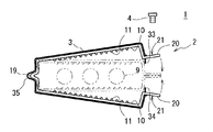
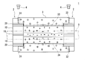
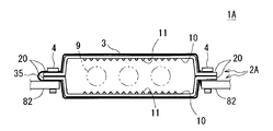
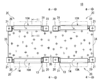
- FIG. 1 is a front view of an electromagnetic shielding tool 1.
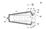
- FIG. 1 is a side view of an electromagnetic shield tool 1.
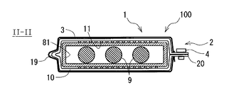
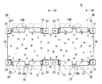
- FIG. 1 is a plan view of a wire harness 100 according to a first embodiment of the present invention. It is a top view of the wire harness 100 of the state attached to the housing
- the electromagnetic shielding tool according to each embodiment shown below is an electrical component attached to an electric wire of a wire harness mounted on a vehicle. And an electromagnetic shielding tool shields noise electromagnetic waves with the electroconductive metal cloth surrounding the circumference
- the electromagnetic shielding tool 1 includes two bracket body parts 2, a metal cloth 3 joined to each of the two bracket body parts 2, and each of the two bracket body parts 2 made of a metal housing. It is comprised by the two screws 4 which are the fixing tools fixed to a body.
- bracket body 2 and one screw 4 constitute a set of brackets
- the other bracket body 2 and the other screw 4 constitute another set of brackets.
- brackets 2 and 4 one bracket body 2 and one screw 4 for fixing the bracket body 2 to the housing are collectively referred to as brackets 2 and 4. That is, the electromagnetic shielding tool 1 includes two sets of brackets 2 and 4.
- One of the two sets of brackets 2 and 4 is fixed to a part of the housing 8 that houses the device to which one end of the electric wire 9 is connected, and the other of the two sets of brackets 2 and 4 is The other end of the electric wire 9 is fixed to a part of the housing 8 that houses the device to be connected.
- the wire harness 100 includes a plurality of electric wires 9 and an electromagnetic shielding tool 1 that collectively covers the periphery of the plurality of electric wires 9.
- the electric wire 9 is an insulated wire composed of a core wire made of a conductive material and an insulating coating made of an insulating material covering the periphery of the core wire.
- a metal terminal (not shown) is connected to the core wire at the end of the electric wire 9.
- the wire harness 100 may be provided with a wire group holding member (not shown) made of a resin material. The wire holding member holds the ends of the plurality of wires 9 in a fixed positional relationship, and electrically insulates the plurality of wires 9 from each other. 1 to 3, the electric wire 9 is drawn by a virtual line (two-dot chain line).
- the metal cloth 3 constituting the electromagnetic shielding tool 1 is a metal thread fabric.
- the metal cloth 3 is a fabric having a mesh structure in which metal yarns are woven so as to intersect each other in the vertical and horizontal directions.
- the metal thread mainly contains copper, for example.
- the metal cloth 3 may have a structure in which a film is attached to a metal yarn cloth.
- the film is made of a resin material and has flexibility.
- the metal cloth 3 has conductivity and flexibility.
- each of the four outer edges of the metal cloth 3 is referred to as a first outer edge 31, a second outer edge 32, a third outer edge 33, and a fourth outer edge 34.
- the first outer edge portion 31 occupies a certain range from the outer edge forming one end in the longitudinal direction of the electric wire 9 to be attached among the four outer edges of the metal cloth 3 to the inside.
- the second outer edge portion 32 occupies a certain range from the outer edge opposite to the first outer edge portion 31 in the metal cloth 3 to the inside.
- the third outer edge portion 33 and the fourth outer edge portion 34 are outer edge portions other than the first outer edge portion 31 and the second outer edge portion 32 among the four outer edge portions of the metal cloth 3. It can be said that the third outer edge portion 33 and the fourth outer edge portion 34 are outer edge portions forming both end portions in a direction surrounding the electric wire 9 in the metal cloth 3.
- the metal cloth 3 of the electromagnetic shielding tool 1 is joined to one of two sets of brackets 2 and 4 described later at the first outer edge portion 31. Similarly, the metal cloth 3 is joined to the other of the two sets of brackets 2 and 4 at the second outer edge portion 32.
- the metal cloth 3 is electrically connected to each of the two metal casings 8 via the two sets of brackets 2 and 4. As a result, the metal cloth 3 is in a grounded state. Details thereof will be described later.
- the third outer edge portion 33 and the fourth outer edge portion 34 of the metal cloth 3 are formed so as to slightly protrude from the ends of the two long portions 10. Has been.
- the bracket body 2 is a bent plate-like member made of a conductive material.
- the bracket body 2 is, for example, a metal member such as a copper alloy, iron, or stainless steel. A plating layer is formed on the surface of the bracket body 2 as necessary.
- the bracket body 2 is a member that relays electrical connection between the metal cloth 3 and the housing 8.
- the bracket main body 2 is fixed to a part of the metal housing 8.
- the bracket body 2 includes two long portions 10, a relay portion 19 that connects one end thereof, and two hooks that are connected to the other ends of the two long portions 10. Part 20.
- Each of the two long portions 10 is a bent plate-like portion.
- Each of the two long portions 10 is formed in a semi-annular shape across a plurality of electric wires 9 to be magnetically shielded.
- the two long portions 10 are formed in an annular shape surrounding the wire 9 by being combined with each other from both sides of the wire 9.
- each long portion 10 is formed in a flat plate shape with an intermediate portion crossing the electric wire 9.
- the shape of each long portion 10 differs depending on the shape of the shield frame portion 81 of the housing 8 that is a fixing destination.
- the two long portions 10 are joined to the metal cloth 3 in a state of being arranged in series along the outer edge portion of the metal cloth 3.
- the metal cloth 3 and the long part 10 are joined by welding, for example.
- the two long portions 10 in one of the two sets of brackets 2 and 4 are joined to the metal cloth 3 in a state of being arranged in series along the first outer edge portion 31 of the metal cloth 3.
- the two long portions 10 in the other of the two sets of brackets 2 and 4 are joined to the metal cloth 3 in a state of being arranged in series along the second outer edge portion 32 of the metal cloth 3.
- the two long portions 10 are formed along a route that is turned back via a relay portion 19 described later. Therefore, the metal cloth 3 joined to the two long portions 10 is held by the two long portions 10 in a folded state at the intermediate portion 35.
- the two long portions 10 are joined to the metal cloth 3 on the outer surface opposite to the side where they are opposed to each other.
- a plurality of protrusions 11 are formed on the inner surfaces of the two long portions 10 on the sides facing each other.
- the plurality of protrusions 11 are formed by embossing. Therefore, a plurality of dents 11x corresponding to each of the plurality of protrusions 11 are formed on the outer surface of each of the two long portions 10.
- the relay portion 19 is a folded plate-like portion, and is formed continuously with one end of each of the two long portions 10. That is, the two long parts 10 and the relay part 19 are comprised with a series of members.
- the relay part 19 has flexibility in the direction in which the turning angle changes. As shown in FIG. 2, due to the flexibility of the relay portion 19, the two long portions 10 can relatively rotate with the relay portion 19 as a fulcrum. Thereby, the bracket main-body part 2 can deform
- the bracket main body 2 in the open state is drawn with a solid line
- the bracket main body 2 in the closed state is drawn with a virtual line (two-dot chain line).
- the metal cloth 3 joined to the two bracket main body portions 2 is also in an open state in which the third outer edge portion 33 and the fourth outer edge portion 34 are separated from each other.
- the metal cloth 3 joined to the two bracket main body portions 2 has the third outer edge portion 33 and the fourth outer edge portion 34 close to each other. It becomes a shape.
- the third outer edge portion 33 and the fourth outer edge portion 34 of the metal cloth 3 are formed so as to slightly protrude from the ends of the two long portions 10. Therefore, when the two bracket main body portions 2 are in the closed state, the third outer edge portion 33 and the fourth outer edge portion 34 of the metal cloth 3 are in contact with each other with almost no gap. Thereby, the metal cloth 3 becomes a cylindrical shape with almost no gap.
- Each of the two flange portions 20 is a flat plate-like portion that is connected to the other end of each of the two long portions 10 and is formed so as to protrude laterally from each of the two long portions 10.
- the bracket body 2 is a series of metal members.
- the bracket body 2 is formed with two long portions 10, a relay portion 19 that connects one end thereof, and two flange portions 20 that are connected to the other ends of the two long portions 10. That is, the two long portions 10 are constituted by a series of metal members together with a flexible relay portion 19 connecting one end thereof and two flange portions 20 connected to the other ends of the two long portions 10. ing.
- each of the two flange portions 20 overlap. Further, each of the two flange portions 20 is formed with a screw hole 21 that is a through hole that communicates in a state where they overlap each other, and to which the screw 4 is attached.
- the bracket body 2 is formed in an annular shape by overlapping the two flanges 20. Further, the two overlaid flange portions 20 are held in a combined state when the screws 4 are attached. Thereby, the ends of each of the two long portions 10 are connected to each other, and the two long portions 10 are held in an annular shape.
- the two flange portions 20 and the screw 4 are an example of a connecting portion that connects the end portions of the two long portions 10 to hold the two long portions 10 in an annular shape.
- a screw thread to be screwed with the screw 4 is formed at the inner edge portion of the screw hole 21 in each of the two flange portions 20. Thereby, the screw 4 can be directly tightened with respect to the flange part 20, and a nut member for joining the two flange parts 20 is not necessary.
- the connecting portion that holds the two long portions 10 in an annular shape may be constituted by two flange portions 20 in which through holes are formed, screws 4, and nut members to which the screws 4 are tightened.
- the nut member is fixed to one of the two overlapping flanges 20 by welding or the like in advance.
- each of the two sets of brackets 2, 4 includes two long portions 10, a relay portion 19 that connects one ends of the two long portions 10, and end portions of the two long portions 10. Are connected to each other.
- Each of the two sets of brackets 2 and 4 has a first outer edge portion 31 and a second outer edge portion 32 on the opposite side of the four outer edge portions of the metal cloth 3 in an annular shape surrounding the wire 9. Hold.
- the length L ⁇ b> 1 of the long portion 10 in each of the two sets of brackets 2, 4 is the third outer edge portion 33 and the fourth outer edge portion 34 of the metal cloth 3. Longer than the length L2.
- the electromagnetic shielding tool 1 having a dimensional configuration as shown in FIG. 4 As a typical first case where the electromagnetic shielding tool 1 having a dimensional configuration as shown in FIG. 4 is adopted, the following cases can be considered. This is a case where the length L2 of the metal cloth 3 is particularly short because the two housings 8 that are the fixing destinations of the two sets of brackets 2 and 4 are arranged close to each other.
- the following cases can be considered. This is a case where the long part 10 of the brackets 2 and 4 is formed to be long because the width of the shield frame part 81 of the housing 8 to which the brackets 2 and 4 are fixed is large.
- FIG. 5 is a plan view of the wire harness 100 attached to the housing 8.
- FIG. 6 is a cross-sectional view of the wire harness 100 attached to the housing 8. The cross-sectional view of FIG. 6 is a cross-sectional view taken along the II-II plane shown in FIG.
- the wire 9 of the wire harness 100 is wired from the outside of the metal housing 8 through the opening of the housing 8 into the housing 8. Further, a metal shield frame portion 81 surrounding the opening is formed at the edge of the opening for introducing the electric wire in the housing 8.
- one of the two sets of brackets 2, 4 is fixed to the shield frame 81 of the housing 8 that houses the device to which one end of the electric wire 9 is connected.
- the other of the two sets of brackets 2 and 4 is fixed to the shield frame portion 81 of the housing 8 that houses a device to which the other end of the electric wire 9 is connected.
- each of the two bracket main body portions 2 that are opened is put on the outside of the shield frame portion 81 of each of the two housings 8 and is also in the open state (non-cylindrical body).
- the metal cloth 3 is put on a portion of the electric wire 9 that extends over the two housings 8.
- each of the two bracket body portions 2 is closed on the outside of the shield frame portion 81. Accordingly, in each of the two bracket main body portions 2, the two long portions 10 sandwich the shield frame portion 81, and the metal cloth 3 has a cylindrical shape surrounding the wire 9. At this time, the plurality of protrusions 11 of the two long portions 10 strongly press against the outer surface of the shield frame portion 81. That is, the force by which the two long portions 10 sandwich the shield frame portion 81 is concentrated on the tops of the plurality of protrusions 11.
- each of the two screws 4 is inserted into the screw holes 21 of the two flange portions 20 that overlap each other in each of the two bracket main body portions 2, and the two flange portions 20 are held in an overlapped state by the screws 4. . Accordingly, each of the two bracket main body portions 2 is held in a closed state and is fixed to the shield frame portion 81.
- each of the two bracket main body portions 2 and each of the two housings 8 are electrically connected. . Therefore, the conductive metal cloth 3 bonded to each of the two bracket main body portions 2 is also electrically connected to each of the two housings 8.
- the metal cloth 3 shields noise electromagnetic waves toward the electric wire 9 by being electrically connected to the housing 8 in a state of surrounding the electric wire 9.
- the two long portions 10 constituting each of the two sets of brackets 2 and 4 are fixed to the shield frame portion 81 in the metal housing 8. These two long portions 10 relay the electrical connection between the metal cloth 3 and the housing 8.
- the metal cloth 3 is electrically connected to the housing 8 via the two sets of brackets 2 and 4 and is in a grounded state.
- the two long portions 10 made of a conductive material are combined from both sides of the electric wire 9 and held in an annular shape. Thereby, the metal cloth 3 joined to the two long portions 10 is formed in a cylindrical shape surrounding the wire 9.
- the electromagnetic shielding tool 1 since the electromagnetic shielding tool 1 is not a member formed in a cylindrical shape in advance, it can be attached to the electric wire 9 later. More specifically, the electromagnetic shielding tool 1 can be attached to the electric wire 9 after a connector or the like is attached to the end. Further, the electromagnetic shield 1 can be attached to the electric wire 9 after the wiring from the outside to the inside of the housing 8 is performed.
- the metal cloth 3 of the size with no excess and deficiency should just be employ
- the two long portions 10 constituting each of the two sets of brackets 2, 4 are in an annular shape with the shield frame portion 81 of the housing 8 sandwiched therebetween, and the flange portion 20 and the screw 4. It is connected by a connecting part composed of Further, the connecting portion holds the combined two long portions 10 in an annular shape, so that the metal cloth 3 joined to the two long portions 10 is held in a cylindrical shape surrounding the periphery of the electric wire 9.
- the two sets of brackets 2 and 4 serve to hold the metal cloth 3 in a cylindrical shape and to maintain an electrical connection between the metal cloth 3 and the shield frame portion 81 of the housing 8. Therefore, when the electromagnetic shielding tool 1 is employed, the man-hours for managing and handling parts are simplified compared to the case where a plurality of members are handled by employing a conventional braided wire and a caulking metal fitting.
- the electromagnetic shielding tool 1 can also surround the electric wire 9 along the curved path.
- the surface of the metal cloth 3 is a minute uneven surface formed by fine metal wires, like the surface of the braided wire, the frictional resistance is very small. Therefore, when the metal cloth 3 is sandwiched and fixed between the shield frame portion 81 of the housing and another fixing member such as a caulking metal fitting, the metal cloth 3 is easily slid from the shield frame portion 81.
- the metal cloth 3 and the long portions 10 of the two sets of brackets 2 and 4 are joined in advance. Therefore, it is possible to directly fix the two sets of brackets 2 and 4 to the shield frame portion 81 without using the metal cloth 3. Therefore, the problem that the electromagnetic shield 1 is detached from the shield frame portion 81 of the housing 8 is unlikely to occur.
- the frictional resistance between the long portion 10 and the shield frame portion 81 is increased by the action of the plurality of protrusions 11 formed on the inner surface of the long portion 10. Accordingly, the holding force of the brackets 2 and 4 with respect to the shield frame portion 81 is increased. As a result, generation
- the electromagnetic shielding tool 1 does not need to shift the position of the metal cloth 3 to one side in the longitudinal direction of the electric wire 9 in the attaching work to the housing 8. Therefore, the electromagnetic shielding tool 1 can be attached by an easy operation.
- the width of the shield frame portion 81 of the housing 8 that is the fixing destination of the brackets 2 and 4 is large, the length L1 of the long portion 10 is correspondingly long, and a relationship of L1> L2 may be considered. . Even in such a case, if the electromagnetic shielding tool 1 including the brackets 2 and 4 that can be directly fixed to the shield frame portion 81 is employed, the effect of being difficult to come off from the shield frame portion 81 of the housing 8 is more remarkable. It becomes.
- the two long portions 10 in each of the two sets of brackets 2 and 4 are constituted by a series of members together with the relay portion 19. Therefore, when the electromagnetic shielding tool 1 is employed, the number of parts is reduced as compared with the case where the two long portions 10 are separate members. Therefore, the man-hour for attachment to the housing 8 can be reduced.
- the metal cloth 3 is joined to the outer surface of the long portion 10.
- the metal cloth 3 is not sandwiched between the long portion 10 and the shield frame portion 81 of the housing 8. Therefore, in order to prevent the metal cloth 3 from being sandwiched, in the long portion 10, the portion that contacts the shield frame portion 81 and the portion that is joined to the metal cloth 3 do not need to be formed separately. Accordingly, it is possible to reduce the size of the long portion 10 (the bracket main body portion 2).
- an electromagnetic shielding tool 1A according to a second embodiment of the present invention will be described with reference to FIGS.
- This electromagnetic shielding tool 1A is different from the electromagnetic shielding tool 1 shown in FIGS. 1 to 6 in that two long portions 10 are configured as separate members. 7 to 9, the same components as those shown in FIGS. 1 to 6 are denoted by the same reference numerals.
- the electromagnetic shielding tool 1A and the electromagnetic shielding tool 1 will be described.
- FIG. 7 is a front view of the electromagnetic shield 1A before attachment
- FIG. 8 is a front view of the electromagnetic shield 1A after the first attachment
- FIG. 9 is a front view of the electromagnetic shield 1A after the second attachment. It is. 7 and 8, the electric wire 9 and the shield frame portion 81 of the housing 8 are drawn with imaginary lines (two-dot chain lines). Similarly, in FIG. 9, the electric wire 9 is drawn with a virtual line (two-dot chain line).
- the electromagnetic shielding tool 1A includes a metal cloth 3 and two sets of brackets 2A and 4.
- Each of the two sets of brackets 2 ⁇ / b> A and 4 includes two bracket main body portions 2 ⁇ / b> A and two screws 4.
- Each of the two bracket main body portions 2A has one long portion 10 formed in a semi-annular shape spanning over the electric wires 9, and two flange portions 20 formed continuously to both ends thereof.
- the electromagnetic shielding tool 1A includes a single metal cloth 3 and four bracket body portions 2A.
- each of the long portions 10 is configured as a part of each of the four bracket main body portions 2A that are independent members. Also in the electromagnetic shielding tool 1 ⁇ / b> A, each of the long portions 10 is joined to the metal cloth 3 in a state where the two long portions 10 are arranged in series along the outer edge portion of the metal cloth 3.
- the two long portions 10 in one of the two sets of brackets 2 ⁇ / b> A and 4 are joined to the metal cloth 3 in a state of being arranged in series along the first outer edge portion 31 of the metal cloth 3. ing.
- the two long portions 10 in the other of the two sets of brackets 2 ⁇ / b> A and 4 are joined to the metal cloth 3 in a state of being arranged in series along the second outer edge portion 32 of the metal cloth 3.
- the metal cloth 3 and the long part 10 are joined by welding, for example.
- the two bracket body portions 2 ⁇ / b> A when the two bracket body portions 2 ⁇ / b> A are combined from both sides of the electric wire 9, the two long portions 10 are formed in an annular shape and joined to each of the two bracket body portions 2 ⁇ / b> A in the metal cloth 3. Folded at the intermediate part 35 between the two parts.
- the two bracket body portions 2A are combined in a state where the two long portions 10 sandwich the shield frame portion 81 of the housing 8.
- the metal cloth 3 joined to the two bracket main body portions 2 has a cylindrical shape in which the third outer edge portion 33 and the fourth outer edge portion 34 are close to each other.
- the two bracket body portions 2 ⁇ / b> A are combined with the shield frame portion 81 of the housing 8 sandwiched therebetween.
- the two long portions 10 sandwich the shield frame portion 81, and the metal cloth 3 has a cylindrical shape surrounding the electric wire 9.
- the operation of the plurality of protrusions 11 is as described above.
- each of the four screws 4 is inserted into the screw holes 21 of the two flange portions 20 that overlap each other at both ends of the two pairs of bracket main body portions 2A, and the two flange portions 20 are held in a state of being overlapped by the screws 4. Is done.
- each of the two pairs of bracket main body portions 2 ⁇ / b> A is held in an annular shape with the shield frame portion 81 interposed therebetween, and is fixed to the shield frame portion 81.
- the electromagnetic shielding tool 1A is normally fixed to the shield frame 81 in the form shown in FIG. 8, but for example, as shown in FIG. 9, it is fixed to a part of the housing 8 in another form. It is also conceivable.
- the pair of bracket main body portions 2 ⁇ / b> A combined from both sides of the electric wire 9 is in two flange portions 20 at both ends thereof with respect to the support plate 82 formed to protrude from the housing 8. It is fixed with screws 4. Since the connecting structure for connecting the two long portions 10 is provided at two positions on both ends of the bracket main body portion 2A, the electromagnetic shielding tool 1A can be fixed in a form as shown in FIG. It is. However, in this case, the protrusion 11 of the long portion 10 is not necessary.
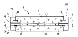
- an electromagnetic shielding tool 1B according to a third embodiment of the present invention and a wire harness 100B including the same will be described with reference to FIGS.
- This electromagnetic shielding tool 1B differs in the structure of the one edge part of the two elongate parts 10 compared with the electromagnetic shielding tool 1 shown by FIGS. 10 to 12, the same components as those shown in FIGS. 1 to 6 are denoted by the same reference numerals.
- the electromagnetic shielding tool 1B and the electromagnetic shielding tool 1 will be described.
- FIG. 10 is a front view of the electromagnetic shielding tool 1B
- FIG. 11 is a side view of the electromagnetic shielding tool 1B
- FIG. 12 is a side view of the wire harness 100B.
- casing 8 is drawn with the virtual line (two-dot chain line).
- the electric wire 9 is drawn with a virtual line (two-dot chain line).
- the electromagnetic shielding tool 1B includes two sets of brackets 2B and 4 as with the electromagnetic shielding tool 1.
- the end of one of the two long portions 10 projects to the other long portion 10 side from the flange portion 20, and the other length
- An extension 12 that overlaps the end of the scale 10 is formed.
- the metal cloth 3 is formed in the magnitude
- Each of the first outer edge portion 31 and the second outer edge portion 32 of the metal cloth 3 is joined to the long portion 10 in a range extending over the extension portion 12 of the long portion 10.
- the connecting portion constituted by the flange portion 20 and the screw 4 is two in a state where both ends joined to the metal cloth 3 in each of the two long portions 10 overlap.
- the long part 10 is connected.
- one of the two end portions of the two long portions 10 is an extension portion 12.
- the metal cloth 3 overlaps at the third outer edge portion 33 and the fourth outer edge portion 34 that form both ends in the direction surrounding the periphery of the electric wire 9, and substantially has a gap. Not held in a cylindrical shape. Therefore, noise electromagnetic waves are shielded more reliably, and stable shielding performance can be obtained.
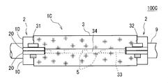
- an electromagnetic shielding tool 1C according to a fourth embodiment of the present invention and a wire harness 100C including the same will be described with reference to FIGS.
- This electromagnetic shielding tool 1C has a configuration in which a metal cloth joining member 5 is added to the electromagnetic shielding tool 1 shown in FIGS. 13 and 14, the same components as those shown in FIGS. 1 to 6 are given the same reference numerals.
- the electromagnetic shielding tool 1C and the electromagnetic shielding tool 1 will be described.
- FIG. 13 is a side view of the electromagnetic shielding tool 1C
- FIG. 14 is a side view of a wire harness 100C including the electromagnetic shielding tool 1C and the electric wires 9.
- the electric wire 9 is drawn with the virtual line (two-dot chain line).
- FIG. 13 shows the electromagnetic shielding tool 1C in the open state.
- the metal cloth joining member 5 included in the electromagnetic shielding tool 1C is a plate-like metal member joined to each of the third outer edge part 33 and the fourth outer edge part 34 of the metal cloth 3 by welding.
- the metal cloth joining member 5 is joined to one of the third outer edge portion 33 and the fourth outer edge portion 34 in the metal cloth 3.
- the electromagnetic shield 1 ⁇ / b> C is closed and attached to the electric wire 9 and the shield frame portion 81 of the housing 8. Thereafter, the metal cloth joining member 5 and the remaining one of the third outer edge portion 33 and the fourth outer edge portion 34 in the metal cloth 3 are joined by welding.
- the third outer edge portion 33 of the metal cloth 3 is bonded to one surface of the metal cloth bonding member 5, and the fourth outer edge portion 34 of the metal cloth 3 is bonded to the other surface of the metal cloth bonding member 5. Is done. Therefore, in a state where both the third outer edge portion 33 and the fourth outer edge portion 34 of the metal cloth 3 are bonded to the metal cloth bonding member 5, the third outer edge portion 33 and the fourth outer edge portion 34 overlap each other. Held in a state.
- the metal cloth 3 is formed in a cylindrical shape with no gap together with the metal cloth joining member 5. Therefore, noise electromagnetic waves are shielded more reliably, and stable shielding performance can be obtained.
- the plurality of metal cloth joining members 5 are joined to the third outer edge portion 33 and the fourth outer edge portion 34 of the metal cloth 3 with a space therebetween. Therefore, the flexibility of the metal cloth 3 is not impaired. Therefore, the electromagnetic shielding tool 1 ⁇ / b> C can also surround the electric wire 9 along the curved path.
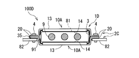
- an electromagnetic shield 1D according to a fifth embodiment of the present invention and a wire harness 100D including the same will be described with reference to FIGS.
- This electromagnetic shielding tool 1D is different from the electromagnetic shielding tool 1A shown in FIGS. 7 to 9 in the structure of joining the long part of the bracket body and the metal cloth.
- the wire harness 100D includes an electromagnetic shield 1D and a plurality of electric wires 9, and further includes an electric wire holding member 91 that holds end portions of the plurality of electric wires 9 in a fixed positional relationship. 15 to 19, the same components as those shown in FIGS. 1 to 14 are designated by the same reference numerals.
- only different points of the electromagnetic shielding tool 1D from the electromagnetic shielding tool 1A will be described.
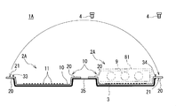
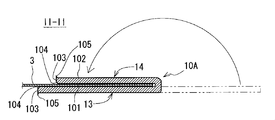
- FIG. 15 is a plan view of the electromagnetic shielding tool 1D
- FIG. 16 is a cross-sectional view of a joint (crimped portion) between the long portion and the metal cloth in the electromagnetic shielding tool 1D
- FIG. 17 is a front view of the electromagnetic shielding tool 1D.
- FIG. 16 is a cross-sectional view taken along the line II-II in FIG. 18 is a front view of the wire harness 100D
- FIG. 19 is a plan view of the wire harness 100D.
- the electric wire 9 and the electric wire holding member 91 are drawn with the virtual line (two-dot chain line).
- the electromagnetic shielding tool 1D includes a metal cloth 3 and two sets of brackets 2C and 4 in the same manner as the electromagnetic shielding tools 1 and 1A.
- Each of the two sets of brackets 2 ⁇ / b> C and 4 includes two bracket main body portions 2 ⁇ / b> C and two screws 4.
- Each of the two bracket main body portions 2C has one long portion 10A formed in a semi-annular shape spanning over the electric wires 9, and two flange portions 20 formed continuously to both ends thereof.
- the electromagnetic shielding tool 1D includes a single metal cloth 3 and four bracket body portions 2C.
- each of the long portions 10A is configured as a part of each of the four bracket main body portions 2C.
- the four bracket main body portions 2C are independent members.
- each of the long portions 10 ⁇ / b> A is joined to the metal cloth 3 in a state where the two long portions 10 ⁇ / b> A are arranged in series along the outer edge portion of the metal cloth 3.
- the two long portions 10 ⁇ / b> A in one of the two pairs of brackets 2 ⁇ / b> C and 4 are joined to the metal cloth 3 in a state of being arranged in series along the first outer edge portion 31 of the metal cloth 3.
- the two long portions 10 ⁇ / b> A in the other of the two sets of brackets 2 ⁇ / b> A and 4 are joined to the metal cloth 3 in a state of being arranged in series along the second outer edge portion 32 of the metal cloth 3.
- each of the long portions 10A is joined to the metal cloth 3 by being crimped to the outer edge of the metal cloth 3. That is, each of the two long portions 10 ⁇ / b> A in one of the two sets of bracket main body portions 2 ⁇ / b> C is joined to the metal cloth 3 by being crimped to the first outer edge portion 31 of the metal cloth 3. Similarly, each of the two long portions 10 ⁇ / b> A in the other of the two sets of bracket main body portions 2 ⁇ / b> C is joined to the metal cloth 3 by being crimped to the third outer edge portion 33 of the metal cloth 3.
- Each of the long portions 10 ⁇ / b> A has the following structure for being crimped to the outer edge portion of the metal cloth 3. That is, as shown in FIGS. 15 and 16, each of the long portions 10 ⁇ / b> A has a base portion 13 and a folded portion 14 connected to the base portion 13.
- the base portion 13 of the long portion 10 ⁇ / b> A is a portion along the outer edge portion (the first outer edge portion 31 or the second outer edge portion 32) of the metal cloth 3.
- the folded portion 14 connected to the base portion 13 is a portion that is folded and overlapped with the base portion 13.
- the folded portion 14 sandwiches the outer edge portion of the metal cloth 3 between the base portion 13 and the folded portion 14.
- the long portion 10 ⁇ / b> A is crimped to the outer edge portion of the metal cloth 3 by sandwiching the outer edge portion of the metal cloth 3 between the base portion 13 and the folded portion 14.
- the folded portion 14 before being folded is drawn with a virtual line.
- a chamfered portion 104 is a boundary portion between the first main surface 101 and the end surface 103 in the portion crimped to the metal cloth 3 of each of the long portions 10 ⁇ / b> A.
- the first main surface 101 is a surface in contact with the metal cloth 3 in each of the long portions 10A.
- the surface of the chamfered portion 104 forms a boundary between the first main surface 101 and the end surface 103, and is a curved surface convex outward.
- the first main surface 101 of the long portion 10A is an inner surface that is in contact with the metal cloth 3, and the second main surface on the opposite side of the first main surface 101.
- the surface 102 is an outer surface opposite to the metal cloth 3.
- the plate material that is the base of the long portion 10A is obtained by punching a plate-shaped metal base material.
- the first main surface 101 of the long portion 10A is a surface on the side to which the punch blade is applied in the punching process
- the second main surface 102 of the long portion 10A is supported by the die in the punching process. It is thought that it is a surface.
- the burr 105 generated by the punching process is formed at the boundary portion between the second main surface 102 and the end surface 103, and the burr 105 does not cause damage to the metal cloth 3.
- the shapes of the punch blade and the die it is possible to form the chamfered portion 104 without requiring a special chamfering process.
- the electric wire holding member 91 is made of a non-conductive material.
- the electric wire holding member 91 is a member that holds the ends of the plurality of electric wires 9 in a fixed positional relationship and electrically insulates the electric wires 9 from each other.
- the electric wire holding member 91 is a non-conductive synthetic resin member.
- the electric wire holding member 91 is a thermoplastic resin member formed by insert molding using the ends of the plurality of electric wires 9 arranged in parallel as insert portions.
- the wire holding member 91 is fitted into an opening formed in the housing. Thereby, the clearance gap between the electric wire 9 and housing
- the electromagnetic shield 1D of the wire harness 100D is fixed to a part of the housing 8.
- the pair of bracket main body portions 2 ⁇ / b> C combined from both sides of the electric wire 9 is supported on the support plate 82 formed by protruding from the housing 8 at the two flange portions 20 at both ends thereof. It is fixed with screws 4.
- Connection structures that connect the two long portions 10 are provided at two locations on both ends of the bracket main body portion 2C. Therefore, the electromagnetic shielding tool 1D can be fixed in a form as shown in FIG.
- the length of the long portion 10A in each of the two sets of brackets 2C and 4 is the same as that of the electromagnetic shield 1 shown in FIG. It is conceivable that L1 is longer than the length L2 of the third outer edge portion 33 and the fourth outer edge portion 34 of the metal cloth 3.
- each of the long portions 10 ⁇ / b> A is joined to the metal cloth 3 by being crimped to the outer edge portion of the metal cloth 3. Therefore, the possibility that the thin metal cloth 3 is damaged by welding can be avoided. Therefore, it is possible to join the long portion 10A and the metal cloth 3 while preventing the thin metal cloth 3 from being damaged.
- the chamfered portion 104 is a boundary portion between the first main surface 101 and the end surface 103 in contact with the metal cloth 3 in the portion crimped to the metal cloth 3 of each of the long portions 10A. This prevents the metal cloth 3 from being damaged by rubbing against the corners of the edges of the long portion.
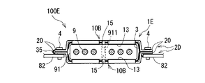
- FIGS. 20 to 22 an electromagnetic shield 1E according to a sixth embodiment of the present invention and a wire harness 100E including the same will be described with reference to FIGS.
- This electromagnetic shielding tool 1E has a structure in which some elements of the long portion are added to the electromagnetic shielding tool 1D shown in FIGS. 20 to 22, the same components as those shown in FIGS. 1 to 19 are denoted by the same reference numerals.
- the electromagnetic shielding tool 1E and the electromagnetic shielding tool 1D will be described.
- FIG. 20 is a plan view of the electromagnetic shielding tool 1E
- FIG. 21 is a front view of the electromagnetic shielding tool 1E
- FIG. 22 is a front view of the wire harness 100E.
- the electric wire 9 and the electric wire holding member 91 are drawn with the virtual line (two-dot chain line).
- the electromagnetic shielding tool 1E includes a metal cloth 3 and two sets of brackets 2D and 4 in the same manner as the electromagnetic shielding tools 1, 1A, and 1E.
- Each of the two sets of brackets 2D and 4 is composed of two bracket main body portions 2D and two screws 4.
- Each of the two bracket main body portions 2D has one long portion 10B formed in a semi-annular shape spanning over the electric wires 9, and two flange portions 20 formed continuously to both ends thereof.
- the electromagnetic shielding tool 1E includes one metal cloth 3 and four bracket body portions 2D. Further, in the electromagnetic shielding tool 1E, each of the long portions 10B is configured as a part of each of the four bracket main body portions 2D which are independent members. Also in the electromagnetic shielding tool 1E, each of the long portions 10B is joined to the metal cloth 3 by pressure bonding in a state where the two long portions 10B are arranged in series along the outer edge portion of the metal cloth 3.
- each of the long portions 10B has one base portion 13 and a plurality of folded portions 14 connected to the base portion 13.
- each of the long portions 10B has two folded portions 14 formed with a space therebetween.
- each of the two long portions 10B in each of the two sets of brackets 2D and 4 is formed with a standing portion 15 for positioning in a direction in which they are opposed to each other.
- the standing upright portion 15 for positioning is formed at a position between the two folded portions 14 in the long portion 10B.
- the upright portion 15 is a portion where a part of the plate-like long portion 10B is bent.
- the wire harness 100 ⁇ / b> E also includes a plurality of electric wires 9, an electromagnetic shield 1 ⁇ / b> E, and an electric wire holding member 91, similar to the wire harness 100 ⁇ / b> D.
- the wire harness 100 ⁇ / b> E includes six electric wires 9, and these six electric wires 9 include the three electric wires 9 that transmit the first three-phase alternating current and the second three electric wires 9. And three electric wires 9 for transmitting a phase alternating current.
- the upright portion 15 is fitted into a positioning hole 911 formed in the electric wire holding member 91.
- the electric wire holding member 91 is a mating member to which the bracket body 2D is connected. Thereby, it becomes easy to connect bracket main-body part 2D and the electric wire holding member 91 by the correct positional relationship.
- the positioning hole 911 transmits a portion of the wire holding member 91 that holds the three wires 9 that transmit the first three-phase alternating current and the second three-phase alternating current. It is formed between the three electric wire 9 parts.
- the two long portions 10 combined with each other are formed in the same shape, but it is also conceivable that the two long portions 10 combined with each other are formed in different shapes. It is done.
- the electromagnetic shielding tool and the wire harness according to the present invention can be freely combined with the above-described embodiments within the scope of the invention described in each claim, or can be modified or partially omitted as appropriate. It is also possible to constitute by doing.
Landscapes
- Engineering & Computer Science (AREA)
- Mechanical Engineering (AREA)
- Architecture (AREA)
- Civil Engineering (AREA)
- Structural Engineering (AREA)
- Power Engineering (AREA)
- Microelectronics & Electronic Packaging (AREA)
- Shielding Devices Or Components To Electric Or Magnetic Fields (AREA)
- Insulated Conductors (AREA)
- Details Of Indoor Wiring (AREA)
Priority Applications (4)
| Application Number | Priority Date | Filing Date | Title |
|---|---|---|---|
| US14/373,152 US9241431B2 (en) | 2012-01-23 | 2013-01-17 | Electromagnetic shielding tool and wire harness |
| EP13741027.0A EP2797189B1 (fr) | 2012-01-23 | 2013-01-17 | Outil de blindage électromagnétique et faisceau électrique |
| KR1020147020605A KR101602592B1 (ko) | 2012-01-23 | 2013-01-17 | 전자 실드 기구 및 와이어 하니스 |
| CN201380006279.8A CN104067468B (zh) | 2012-01-23 | 2013-01-17 | 电磁屏蔽件以及线束 |
Applications Claiming Priority (4)
| Application Number | Priority Date | Filing Date | Title |
|---|---|---|---|
| JP2012-010943 | 2012-01-23 | ||
| JP2012010943 | 2012-01-23 | ||
| JP2012-187463 | 2012-08-28 | ||
| JP2012187463A JP5942703B2 (ja) | 2012-01-23 | 2012-08-28 | 電磁シールド具及びワイヤハーネス |
Publications (1)
| Publication Number | Publication Date |
|---|---|
| WO2013111665A1 true WO2013111665A1 (fr) | 2013-08-01 |
Family
ID=48873386
Family Applications (1)
| Application Number | Title | Priority Date | Filing Date |
|---|---|---|---|
| PCT/JP2013/050791 Ceased WO2013111665A1 (fr) | 2012-01-23 | 2013-01-17 | Outil de blindage électromagnétique et faisceau électrique |
Country Status (6)
| Country | Link |
|---|---|
| US (1) | US9241431B2 (fr) |
| EP (1) | EP2797189B1 (fr) |
| JP (1) | JP5942703B2 (fr) |
| KR (1) | KR101602592B1 (fr) |
| CN (1) | CN104067468B (fr) |
| WO (1) | WO2013111665A1 (fr) |
Cited By (3)
| Publication number | Priority date | Publication date | Assignee | Title |
|---|---|---|---|---|
| CN105981227A (zh) * | 2014-02-13 | 2016-09-28 | 丰田自动车株式会社 | 端子台 |
| CN107112694A (zh) * | 2015-01-07 | 2017-08-29 | 丰田自动车株式会社 | 屏蔽电线连接结构 |
| WO2022002925A1 (fr) * | 2020-07-01 | 2022-01-06 | Karl Storz Se & Co. Kg | Boîte de blindage rf, instrument médical et procédé |
Families Citing this family (15)
| Publication number | Priority date | Publication date | Assignee | Title |
|---|---|---|---|---|
| EP2772394B1 (fr) * | 2011-10-24 | 2018-10-10 | Honda Motor Co., Ltd. | Structure de couverture protectrice de câblage pour véhicule électrique |
| JP2015095355A (ja) * | 2013-11-12 | 2015-05-18 | 住友電装株式会社 | ワイヤハーネス |
| JP6036653B2 (ja) * | 2013-11-12 | 2016-11-30 | 住友電装株式会社 | シールドコネクタ |
| JP2016100463A (ja) * | 2014-11-21 | 2016-05-30 | 株式会社オートネットワーク技術研究所 | 導電部材及び電磁シールド具 |
| JP6432303B2 (ja) * | 2014-11-21 | 2018-12-05 | 株式会社オートネットワーク技術研究所 | 導電部材及び電磁シールド具 |
| WO2016111070A1 (fr) * | 2015-01-07 | 2016-07-14 | トヨタ自動車株式会社 | Structure de connexion par fils électriques blindés |
| JP6141363B2 (ja) * | 2015-07-22 | 2017-06-07 | 住友電装株式会社 | シールドコネクタ |
| JP6614017B2 (ja) | 2016-04-28 | 2019-12-04 | 株式会社オートネットワーク技術研究所 | 電磁シールド具及びワイヤーハーネス |
| US10103527B2 (en) * | 2016-07-05 | 2018-10-16 | Mitsubishi Electric Corporation | Shielded harness including molded body and fixing member |
| JP2018116891A (ja) * | 2017-01-20 | 2018-07-26 | 株式会社オートネットワーク技術研究所 | 配線モジュール |
| JP6900243B2 (ja) * | 2017-06-07 | 2021-07-07 | 日置電機株式会社 | シールド体およびセンサ |
| JP6899730B2 (ja) * | 2017-08-04 | 2021-07-07 | 矢崎総業株式会社 | ワイヤハーネス |
| JP6955219B2 (ja) * | 2018-03-30 | 2021-10-27 | 住友電装株式会社 | ワイヤハーネス |
| EP4614743A1 (fr) * | 2024-03-06 | 2025-09-10 | Stirling Moulded Composites Limited | Elément de connexion électrique et procédé de fabrication |
| GB202403265D0 (en) * | 2024-03-06 | 2024-04-17 | Stirling Moulded Composites Ltd | Electrical connection member and method of manufacture |
Citations (6)
| Publication number | Priority date | Publication date | Assignee | Title |
|---|---|---|---|---|
| JPS5748683U (fr) * | 1980-09-04 | 1982-03-18 | ||
| JPH0579579A (ja) * | 1991-09-24 | 1993-03-30 | Toyoda Gosei Co Ltd | ブラケツト |
| JPH0715165A (ja) * | 1993-06-25 | 1995-01-17 | Kitagawa Ind Co Ltd | 電磁波シールド材 |
| JP2003197037A (ja) * | 2001-12-26 | 2003-07-11 | Auto Network Gijutsu Kenkyusho:Kk | 機器取付け用ワイヤーハーネス |
| JP2006344398A (ja) | 2005-06-07 | 2006-12-21 | Toyota Motor Corp | シールドシェル |
| JP2009068515A (ja) * | 2007-09-10 | 2009-04-02 | Honda Motor Co Ltd | 長尺部材の保持構造 |
Family Cites Families (14)
| Publication number | Priority date | Publication date | Assignee | Title |
|---|---|---|---|---|
| JPS5748683A (en) | 1980-09-06 | 1982-03-20 | Hitachi Ltd | Diverter for nuclear fusion reactor |
| JPH10224943A (ja) * | 1997-01-31 | 1998-08-21 | Keihin Sokki Kk | シールドチューブ |
| JP4764556B2 (ja) * | 2001-03-06 | 2011-09-07 | 矢崎総業株式会社 | 導体付き導体薄膜シート |
| JP4914539B2 (ja) * | 2001-05-18 | 2012-04-11 | 矢崎総業株式会社 | シールドハーネスの組立方法 |
| US6639148B2 (en) * | 2001-06-20 | 2003-10-28 | Federal-Mogul Systems Protection Group, Inc. | Extendible drain members for grounding RFI/EMI shielding |
| FR2853148B1 (fr) * | 2003-03-24 | 2008-11-14 | Fed Mogul Systems Prot Group | Gaine de blindage electro-magnetique notamment pour proteger des faisceaux de cables dans l'aeronautique. |
| FR2916081B1 (fr) * | 2007-05-07 | 2009-09-25 | Fed Mogul Systems Prot Group S | Gaine de protection electromagnetique en textile. |
| JP2009048952A (ja) * | 2007-08-22 | 2009-03-05 | Auto Network Gijutsu Kenkyusho:Kk | シールド導電体 |
| JP5362206B2 (ja) * | 2007-12-04 | 2013-12-11 | 矢崎総業株式会社 | シールド部材 |
| JP5362207B2 (ja) * | 2007-12-13 | 2013-12-11 | 矢崎総業株式会社 | シールド部材 |
| JP5362270B2 (ja) * | 2008-07-03 | 2013-12-11 | 矢崎総業株式会社 | シールド電線、及び該シールド電線の編組端末処理方法、並びに、編組端末処理装置 |
| JP5293644B2 (ja) * | 2010-03-02 | 2013-09-18 | 住友電装株式会社 | ワイヤハーネスの配索構造 |
| JP5586335B2 (ja) * | 2010-06-10 | 2014-09-10 | 矢崎総業株式会社 | シールド端末接続構造及び方法 |
| JP5880070B2 (ja) * | 2012-01-23 | 2016-03-08 | 株式会社オートネットワーク技術研究所 | 電磁シールド具及びワイヤハーネス |
-
2012
- 2012-08-28 JP JP2012187463A patent/JP5942703B2/ja not_active Expired - Fee Related
-
2013
- 2013-01-17 US US14/373,152 patent/US9241431B2/en active Active
- 2013-01-17 CN CN201380006279.8A patent/CN104067468B/zh not_active Expired - Fee Related
- 2013-01-17 KR KR1020147020605A patent/KR101602592B1/ko not_active Expired - Fee Related
- 2013-01-17 WO PCT/JP2013/050791 patent/WO2013111665A1/fr not_active Ceased
- 2013-01-17 EP EP13741027.0A patent/EP2797189B1/fr not_active Not-in-force
Patent Citations (6)
| Publication number | Priority date | Publication date | Assignee | Title |
|---|---|---|---|---|
| JPS5748683U (fr) * | 1980-09-04 | 1982-03-18 | ||
| JPH0579579A (ja) * | 1991-09-24 | 1993-03-30 | Toyoda Gosei Co Ltd | ブラケツト |
| JPH0715165A (ja) * | 1993-06-25 | 1995-01-17 | Kitagawa Ind Co Ltd | 電磁波シールド材 |
| JP2003197037A (ja) * | 2001-12-26 | 2003-07-11 | Auto Network Gijutsu Kenkyusho:Kk | 機器取付け用ワイヤーハーネス |
| JP2006344398A (ja) | 2005-06-07 | 2006-12-21 | Toyota Motor Corp | シールドシェル |
| JP2009068515A (ja) * | 2007-09-10 | 2009-04-02 | Honda Motor Co Ltd | 長尺部材の保持構造 |
Non-Patent Citations (1)
| Title |
|---|
| See also references of EP2797189A4 |
Cited By (4)
| Publication number | Priority date | Publication date | Assignee | Title |
|---|---|---|---|---|
| CN105981227A (zh) * | 2014-02-13 | 2016-09-28 | 丰田自动车株式会社 | 端子台 |
| CN107112694A (zh) * | 2015-01-07 | 2017-08-29 | 丰田自动车株式会社 | 屏蔽电线连接结构 |
| CN107112694B (zh) * | 2015-01-07 | 2019-04-26 | 丰田自动车株式会社 | 屏蔽电线连接结构 |
| WO2022002925A1 (fr) * | 2020-07-01 | 2022-01-06 | Karl Storz Se & Co. Kg | Boîte de blindage rf, instrument médical et procédé |
Also Published As
| Publication number | Publication date |
|---|---|
| US9241431B2 (en) | 2016-01-19 |
| KR20140105855A (ko) | 2014-09-02 |
| EP2797189A4 (fr) | 2015-07-01 |
| CN104067468B (zh) | 2017-03-15 |
| KR101602592B1 (ko) | 2016-03-10 |
| US20150027772A1 (en) | 2015-01-29 |
| CN104067468A (zh) | 2014-09-24 |
| JP5942703B2 (ja) | 2016-06-29 |
| EP2797189B1 (fr) | 2016-11-09 |
| JP2013176279A (ja) | 2013-09-05 |
| EP2797189A1 (fr) | 2014-10-29 |
Similar Documents
| Publication | Publication Date | Title |
|---|---|---|
| JP5942703B2 (ja) | 電磁シールド具及びワイヤハーネス | |
| JP5880070B2 (ja) | 電磁シールド具及びワイヤハーネス | |
| JP5772640B2 (ja) | 電磁シールド具及びワイヤハーネス | |
| US10236634B2 (en) | Electromagnetic shield member and electromagnetic shield member-equipped wiring device | |
| JP6380227B2 (ja) | 配線装置 | |
| JP2018147901A (ja) | 導電部材 | |
| WO2014034899A1 (fr) | Structure de combinaison de faisceaux de câbles | |
| JP6344611B2 (ja) | コネクタ | |
| JP2013214690A (ja) | 電磁シールド具及びワイヤハーネス | |
| WO2013046405A1 (fr) | Connecteur | |
| JP5772772B2 (ja) | 電磁シールド具及びワイヤハーネス | |
| WO2016080522A1 (fr) | Élément électroconducteur et outil de blindage électromagnétique | |
| JP5772698B2 (ja) | 電磁シールド具及びワイヤハーネス | |
| JP6614017B2 (ja) | 電磁シールド具及びワイヤーハーネス | |
| JP5642440B2 (ja) | コネクタ | |
| JP6326271B2 (ja) | 電線のシールド構造 | |
| JP2011181457A (ja) | 配索材の接続構造 | |
| TWM453991U (zh) | 電連接器 |
Legal Events
| Date | Code | Title | Description |
|---|---|---|---|
| 121 | Ep: the epo has been informed by wipo that ep was designated in this application |
Ref document number: 13741027 Country of ref document: EP Kind code of ref document: A1 |
|
| WWE | Wipo information: entry into national phase |
Ref document number: 14373152 Country of ref document: US |
|
| ENP | Entry into the national phase |
Ref document number: 20147020605 Country of ref document: KR Kind code of ref document: A |
|
| REEP | Request for entry into the european phase |
Ref document number: 2013741027 Country of ref document: EP |
|
| WWE | Wipo information: entry into national phase |
Ref document number: 2013741027 Country of ref document: EP |
|
| NENP | Non-entry into the national phase |
Ref country code: DE |