WO2013122166A1 - Engin à deux bras - Google Patents
Engin à deux bras Download PDFInfo
- Publication number
- WO2013122166A1 WO2013122166A1 PCT/JP2013/053569 JP2013053569W WO2013122166A1 WO 2013122166 A1 WO2013122166 A1 WO 2013122166A1 JP 2013053569 W JP2013053569 W JP 2013053569W WO 2013122166 A1 WO2013122166 A1 WO 2013122166A1
- Authority
- WO
- WIPO (PCT)
- Prior art keywords
- work machine
- attachment
- lever
- drive command
- front work
- Prior art date
- Legal status (The legal status is an assumption and is not a legal conclusion. Google has not performed a legal analysis and makes no representation as to the accuracy of the status listed.)
- Ceased
Links
Images











Classifications
-
- E—FIXED CONSTRUCTIONS
- E02—HYDRAULIC ENGINEERING; FOUNDATIONS; SOIL SHIFTING
- E02F—DREDGING; SOIL-SHIFTING
- E02F3/00—Dredgers; Soil-shifting machines
- E02F3/04—Dredgers; Soil-shifting machines mechanically-driven
- E02F3/96—Dredgers; Soil-shifting machines mechanically-driven with arrangements for alternate or simultaneous use of different digging elements
- E02F3/963—Arrangements on backhoes for alternate use of different tools
- E02F3/964—Arrangements on backhoes for alternate use of different tools of several tools mounted on one machine
-
- B—PERFORMING OPERATIONS; TRANSPORTING
- B25—HAND TOOLS; PORTABLE POWER-DRIVEN TOOLS; MANIPULATORS
- B25J—MANIPULATORS; CHAMBERS PROVIDED WITH MANIPULATION DEVICES
- B25J9/00—Program-controlled manipulators
- B25J9/16—Program controls
- B25J9/1679—Program controls characterised by the tasks executed
- B25J9/1682—Dual arm manipulator; Coordination of several manipulators
-
- E—FIXED CONSTRUCTIONS
- E02—HYDRAULIC ENGINEERING; FOUNDATIONS; SOIL SHIFTING
- E02F—DREDGING; SOIL-SHIFTING
- E02F3/00—Dredgers; Soil-shifting machines
- E02F3/04—Dredgers; Soil-shifting machines mechanically-driven
- E02F3/96—Dredgers; Soil-shifting machines mechanically-driven with arrangements for alternate or simultaneous use of different digging elements
-
- E—FIXED CONSTRUCTIONS
- E02—HYDRAULIC ENGINEERING; FOUNDATIONS; SOIL SHIFTING
- E02F—DREDGING; SOIL-SHIFTING
- E02F3/00—Dredgers; Soil-shifting machines
- E02F3/04—Dredgers; Soil-shifting machines mechanically-driven
- E02F3/96—Dredgers; Soil-shifting machines mechanically-driven with arrangements for alternate or simultaneous use of different digging elements
- E02F3/961—Dredgers; Soil-shifting machines mechanically-driven with arrangements for alternate or simultaneous use of different digging elements with several digging elements or tools mounted on one machine
-
- E—FIXED CONSTRUCTIONS
- E02—HYDRAULIC ENGINEERING; FOUNDATIONS; SOIL SHIFTING
- E02F—DREDGING; SOIL-SHIFTING
- E02F3/00—Dredgers; Soil-shifting machines
- E02F3/04—Dredgers; Soil-shifting machines mechanically-driven
- E02F3/96—Dredgers; Soil-shifting machines mechanically-driven with arrangements for alternate or simultaneous use of different digging elements
- E02F3/965—Dredgers; Soil-shifting machines mechanically-driven with arrangements for alternate or simultaneous use of different digging elements of metal-cutting or concrete-crushing implements
-
- E—FIXED CONSTRUCTIONS
- E02—HYDRAULIC ENGINEERING; FOUNDATIONS; SOIL SHIFTING
- E02F—DREDGING; SOIL-SHIFTING
- E02F9/00—Component parts of dredgers or soil-shifting machines, not restricted to one of the kinds covered by groups E02F3/00 - E02F7/00
- E02F9/20—Drives; Control devices
- E02F9/2004—Control mechanisms, e.g. control levers
- E02F9/2012—Setting the functions of the control levers, e.g. changing assigned functions among operations levers, setting functions dependent on the operator or seat orientation
-
- E—FIXED CONSTRUCTIONS
- E02—HYDRAULIC ENGINEERING; FOUNDATIONS; SOIL SHIFTING
- E02F—DREDGING; SOIL-SHIFTING
- E02F9/00—Component parts of dredgers or soil-shifting machines, not restricted to one of the kinds covered by groups E02F3/00 - E02F7/00
- E02F9/20—Drives; Control devices
- E02F9/22—Hydraulic or pneumatic drives
- E02F9/2278—Hydraulic circuits
- E02F9/2292—Systems with two or more pumps
-
- E—FIXED CONSTRUCTIONS
- E02—HYDRAULIC ENGINEERING; FOUNDATIONS; SOIL SHIFTING
- E02F—DREDGING; SOIL-SHIFTING
- E02F9/00—Component parts of dredgers or soil-shifting machines, not restricted to one of the kinds covered by groups E02F3/00 - E02F7/00
- E02F9/20—Drives; Control devices
- E02F9/22—Hydraulic or pneumatic drives
- E02F9/2278—Hydraulic circuits
- E02F9/2296—Systems with a variable displacement pump
-
- E—FIXED CONSTRUCTIONS
- E02—HYDRAULIC ENGINEERING; FOUNDATIONS; SOIL SHIFTING
- E02F—DREDGING; SOIL-SHIFTING
- E02F9/00—Component parts of dredgers or soil-shifting machines, not restricted to one of the kinds covered by groups E02F3/00 - E02F7/00
- E02F9/20—Drives; Control devices
- E02F9/22—Hydraulic or pneumatic drives
- E02F9/2221—Control of flow rate; Load sensing arrangements
- E02F9/2225—Control of flow rate; Load sensing arrangements using pressure-compensating valves
- E02F9/2228—Control of flow rate; Load sensing arrangements using pressure-compensating valves including an electronic controller
-
- E—FIXED CONSTRUCTIONS
- E02—HYDRAULIC ENGINEERING; FOUNDATIONS; SOIL SHIFTING
- E02F—DREDGING; SOIL-SHIFTING
- E02F9/00—Component parts of dredgers or soil-shifting machines, not restricted to one of the kinds covered by groups E02F3/00 - E02F7/00
- E02F9/20—Drives; Control devices
- E02F9/22—Hydraulic or pneumatic drives
- E02F9/2278—Hydraulic circuits
- E02F9/2285—Pilot-operated systems
Definitions
- the present invention relates to a double-arm type work machine provided with work arms on the right and left sides of the main body of the work machine.
- a double-armed work machine that has work arms on the right and left sides of the main body of the work machine.
- the dual arm type work machine is provided with operation levers corresponding to the left and right work arms. By operating the lever, the actuators provided on the left and right work arms are driven, so that the left and right work arms can be operated independently (see Patent Document 1).
- a control method for synchronizing the operations of the two manipulators is known. That is, only one manipulator (master side) is driven by the operator using the operating lever, and the other manipulator (slave side) is controlled so as to automatically follow it. Synchronize operation.
- the slave side performs feedback control by referring to each joint coordinate on the master side and setting it as a target value (see Patent Document 2).
- a double-armed work machine includes a first front work machine to which a first attachment is attached, a second front work machine to which a second attachment is attached, and a first operating member.
- the second drive device that drives the work machine and the second attachment, and the first and second drive commands are input, and a common drive command that drives the first and second drive devices is generated and output.
- a drive command output device is input.
- the dual-arm work machine further includes an operation selection unit capable of selecting either the first operation member or the second operation member, and is driven.
- the command output device includes first and second drives based on the first drive command from the first operation member selected by the operation selection unit or the second drive command from the second operation member. It is preferable to generate and output a common drive command for driving the apparatus.
- a first operation direction determination unit that determines an operation direction of the first operation member, and an operation direction of the second operation member.
- a second operation direction determination unit to determine; an operation direction of the first operation member determined by the first operation direction determination unit; and an operation direction of the second operation member determined by the second operation direction determination unit.
- a synchronous operation determination unit that determines whether or not they are the same, and the drive command output device has the same operation direction of the first operation member and the operation direction of the second operation member in the synchronous operation determination unit. If it is determined, the common drive command is generated and output based on the first drive command from the first operation member or the second drive command from the second operation member. Is preferred.
- a first operation direction determination unit that determines an operation direction of the first operation member and an operation direction of the second operation member are determined.
- a second operation direction determination unit a first operation amount detection unit that detects an operation amount of the first operation member, a second operation amount detection unit that detects an operation amount of the second operation member, Synchronization for determining whether the operation direction of the first operation member determined by the first operation direction determination unit and the operation direction of the second operation member determined by the second operation direction determination unit are the same.
- An operation determination unit; and the drive command output device determines that the operation direction of the first operation member is the same as the operation direction of the second operation member by the synchronous operation determination unit.
- the operation amount of the first operation member detected by the operation amount detection unit and the second operation amount detected by the second operation amount detection means may generate and output a common driving command.
- a first operation vector computing unit that computes an operation vector of the first operation member, and an operation vector of the second operation member.
- a second operation vector calculation unit to be calculated; an operation vector of the first operation member calculated by the first operation vector calculation unit; an operation vector of the second operation member calculated by the second operation vector calculation unit;
- a synchronous operation determination unit that determines whether or not the operation vectors of the first operation member and the operation vector of the second operation member are determined by the synchronous operation determination unit. If it is determined that they are substantially the same, a common drive command is generated based on the first drive command from the first operation member and / or the second drive command from the second operation member. Output is preferable.
- the drive command output device It is preferable to further comprising a common drive command generation permission unit that prohibits that common to generate a drive command output by.
- the first posture detection unit that detects the posture of the first front work machine and the first attachment; A second posture detection unit that detects a posture of the second front work machine and the second attachment; a posture of the first front work machine and the first attachment detected by the first posture detection unit; A posture determination unit for determining whether or not the second front work machine and the second attachment posture detected by the second posture detection unit are substantially the same; and the first front work machine in the posture determination unit.
- a common drive command is generated and output by the drive command output device.
- the posture determination unit determines that the postures of the first front work machine and the first attachment are not substantially the same as the postures of the second front work machine and the second attachment. It is preferable to further include a common drive command generation permission unit that prohibits generation and output of the drive command.
- the movement of the first front work machine and the first attachment and the movement of the second front work machine and the second attachment are determined.
- the posture determination unit It is determined that the postures of the first front work machine and the first attachment and the postures of the second front work machine and the second attachment are not substantially the same, or the first front work machine is determined by the synchronization selection member. If it is selected not to synchronize the movement of the first attachment with the movement of the second front work machine and the second attachment, a common drive command is generated and output by the drive command output device. It may be prohibited.
- the synchronous operation with a 1st front work machine and a 1st attachment and a 2nd front work machine and a 2nd attachment can be implement
- Arm work machines can be provided at low cost.
- FIG. 1 is a diagram illustrating a double-armed work machine according to a first embodiment.
- FIG. 2 is a diagram illustrating the double-armed work machine according to the first embodiment.
- FIG. 3 is a diagram illustrating the operating device according to the first embodiment.
- FIG. 4 is a diagram showing an outline of the hydraulic circuit.
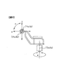
- FIG. 5 is a diagram illustrating the operation direction of the operation device.
- FIG. 6 is a diagram illustrating the swinging directions of the first front work machine and the second front work machine.
- FIG. 7 is a schematic diagram related to the operation control system in the first embodiment.
- FIG. 8 is a schematic diagram related to signal processing performed in each signal generation unit.
- FIG. 9 is a flowchart illustrating a processing flow of the operation signal sharing calculation unit according to the first embodiment.
- FIG. 9 is a flowchart illustrating a processing flow of the operation signal sharing calculation unit according to the first embodiment.
- FIG. 10 is a diagram illustrating an operating device according to the second embodiment.
- FIG. 11 is a schematic diagram related to the operation control system in the second embodiment.
- FIG. 12 is a flowchart illustrating a processing flow of the operation direction determination unit according to the second embodiment.
- FIG. 13 is a flowchart illustrating a processing flow of the operation signal sharing calculation unit according to the second embodiment.
- FIG. 14 is a flowchart illustrating a processing flow of the operation signal sharing calculation unit according to the third embodiment.
- FIG. 15 is a schematic diagram related to the operation control system in the fourth embodiment.
- FIG. 16 is a flowchart illustrating a processing flow of the operation vector determination unit in the fourth embodiment.
- FIG. 17 is a diagram illustrating an arrangement state of the angle sensor.
- FIG. 18 is a schematic diagram related to the operation control system in the fifth embodiment.
- FIG. 19 is a flowchart illustrating a processing flow of the operation direction determination unit in the fifth embodiment.
- FIG. 20 is a diagram for explaining a state in which a work machine transports work objects in parallel.
- FIG. 21 is a diagram illustrating an operating device according to the sixth embodiment.
- FIG. 22 is a schematic diagram related to the operation control system in the sixth embodiment.
- FIG. 23 is a flowchart illustrating a processing flow of the operation direction determination unit in the sixth embodiment.
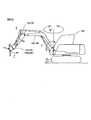
- FIGS. 1 and FIG. 2 are views showing a double-armed work machine in the first embodiment.
- the work machine 200 according to the first embodiment is a work machine configured based on a hydraulic excavator.
- an upper swing body 3 is pivotably attached to a lower traveling body 2 including the travel body 1, and a cab 4 is attached in the vicinity of the center line 3 c in the left-right direction of the upper swing body 3.
- a first front work machine A is provided on the right side and a second front work machine B is provided on the left side from the cab 4 toward the front from the center line 3c.
- the first front work machine A includes a swing post 7a attached to the right side of the upper swing body 3 so as to be swingable in the left-right direction, and a boom attached to the swing post 7a so as to be swingable in the vertical direction. 10a, an arm 12a attached to the boom 10a so as to be swingable in the vertical direction, and a first work tool (first attachment) 14a attached to the arm 12a so as to be swingable (rotatable) in the vertical direction. And a grapple 20a.
- the first front work machine A includes a joint that swingably connects the upper swing body 3 and the swing post 7a, a joint that swingably connects the swing post 7a and the boom 10a, a boom 10a, and an arm 12a. And a joint that rotatably connects the arm 12a and the grapple 20a.
- the first front work machine A is connected to the swing post 7a and the upper swing body 3, and is connected to the swing cylinder 9a that swings the swing post 7a left and right, and the swing post 7a and the boom 10a.
- a boom cylinder 11a (not shown in FIGS. 1 and 2) is provided.
- the first front work machine A is connected to a boom 10a and an arm 12a, and is connected to an arm cylinder 13a that swings the arm 12a up and down, and a work tool that is connected to the arm 12a and the grapple 20a to rotate the grapple 20a up and down. And a cylinder 15a.
- the grapple 20a can be arbitrarily replaced with any one of other working tools such as a cutter or a bucket (not shown).
- the boom 10a and the arm 12a are collectively referred to as a right front working arm.
- the second front work machine B is provided on the left side toward the front of the upper swing body 3.
- the second front work machine B is configured in the same manner as the first front work machine A. Accordingly, the same members as those of the first front work machine A in the second front work machine B are indicated by changing the subscripts from “a” to “b”.
- the second front work machine B has the mounting position of the swing post 7b, the shape and dimensions of the swing post 7b, the boom 10b and the arm 12b, the mounting position of the swing post 7a of the first front work machine A, the swing post 7a, and the boom 10a.
- the shape and dimensions of the arm 12a are the same.
- the grapple 20b is the same work tool (attachment) as the grapple 20a.
- each hydraulic cylinder that drives each part of the second front work machine B are also the same as the characteristics of the corresponding hydraulic cylinders of the first front work machine A. Therefore, detailed description of the second front work machine B is omitted.
- the boom 10b and the arm 12b are also collectively referred to as the left front working arm.
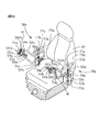
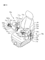
- FIG. 3 is a diagram illustrating the operating device according to the first embodiment.
- a driver's seat 49 is installed in the driver's cab 4, and an operating device 50 a is provided on the right side and an operating device 50 b is provided on the left side of the driver's seat 49.
- the operating device 50a is an operating device for the first front work machine A
- the operating device 50b is an operating device for the second front work machine B.
- the operating device 50a is provided with an operating arm bracket 51a provided on the right side of the driver's seat 49, and attached to the operating arm bracket 51a so as to be able to swing left and right around the swing center axis 73a.
- the operating tool 54a is pivotably mounted around the axis of the operating lever 54a, and is attached to the operating tool rotating lever 55a for instructing the operating tool 14a to rotate, and the distal end of the operating lever 54a. Is provided with a work tool operation switch 56a.
- the operating device 50a is provided on the operating arm bracket 51a, and is provided with an operating arm displacement detector 57a that detects a swing displacement amount of the operating arm 52a and transmits a signal, and an operating lever 52a.
- Operation lever vertical displacement detector 581a for detecting a displacement amount in the vertical direction and transmitting a signal
- a longitudinal displacement detector for an operation lever for detecting a displacement amount in the front and rear direction and transmitting a signal in the same manner 582a.
- the operating device 50a is provided on the operating lever 54a, and is provided on a rotating lever displacement detector 59a that detects a rotational displacement amount of the working tool rotating lever 55a and transmits a signal, and a working tool rotating lever 55a.
- An operation switch displacement detector 60a that detects a displacement amount of the work tool operation switch 56a and transmits a signal is provided.
- the operating device 50b is configured on the left side of the driver's seat in the same manner as the operating device 50a. Therefore, the same members as those of the operation device 50a in the operation device 50b are indicated by changing the subscripts from “a” to “b”, and detailed description thereof is omitted.
- the operation device 50a on the right side can operate both the first front work machine A and the second front work machine B, or on the left side. This is a switch for selecting whether or not both the first front work machine A and the second front work machine B can be operated by the operating device 50b.
- a selection position where both the first front work machine A and the second front work machine B can be operated with the right operation apparatus 50a is referred to as a right operation apparatus selection position.
- a selection position in the operation lever selection switch 61 at which both the first front work machine A and the second front work machine B can be operated with the left operation apparatus 50b is referred to as a left operation apparatus selection position.
- the operation lever selection switch 61 is provided, for example, near the tip of the operation arm 52a.
- the double-arm synchronous mode switch 62 is a switch for selecting either the double-arm synchronous mode or the normal mode described below, and is provided, for example, near the tip of the operation arm 52b. .
- the work machine 200 according to the first embodiment is provided with a normal mode and a double-arm synchronous mode as operation modes of the first front work machine A and the second front work machine B.
- the normal mode is an operation mode for operating the first front work machine A with the right operating device 50a and operating the second front work machine B with the left operating device 50b. Therefore, when the operation mode is set to the normal mode by the operation of the double arm synchronous mode switch 62, the operation of the first front work machine A and the second front work machine B is the same as that of the conventional double arm work machine. It becomes. The operation of the first front work machine A and the second front work machine B in the normal mode will be described in detail later.
- the double-arm synchronization mode is an operation mode that enables the following operations (a) and (b).
- B When the left operation device selection position is selected by the operation lever selection switch 61, the left and right cylinders of the boom cylinders 11a and 11b, the arm cylinders 13a and 13b, and the work tool cylinders 15a and 15b are moved to the left operation lever 54b. In addition, the operation tool rotation lever 55b alone can be operated simultaneously.
- the operation of the first front work machine A and the second front work machine B in the double-arm synchronous mode will be described in detail later.
- the swing speeds of the booms 10a and 10b are in a simple increase relationship, for example, proportional to the displacement amounts of the operation levers 54a and 54b, and the displacements of the operation levers 54a and 54b cause the booms 10a and 10b to swing.
- Speed control for example, proportional to the displacement amounts of the operation levers 54a and 54b, and the displacements of the operation levers 54a and 54b cause the booms 10a and 10b to swing.
- the first work tool 14a and the second work tool 14b (hereinafter simply referred to as work tools 14a and 14b) are rotated in a direction that coincides with the rotation direction of the work tool rotation levers 55a and 55b (FIG. 6). Arrow Z).
- the swinging speed of the work tools 14a and 14b is in a proportional increase relationship with the displacement amount of the rotation levers 55a and 55b, for example, the displacement of the rotation levers 55a and 55b.
- the speed of the swing of the is controlled.
- the swing speeds of the swing posts 7a and 7b are in a simple increase relationship, for example, a proportional relationship with the displacement amounts of the operation arms 52a and 52b, and the displacement of the operation arms 52a and 52b is the swing of the swing posts 7a and 7b.
- Speed control the movement for example, a proportional relationship with the displacement amounts of the operation arms 52a and 52b, and the displacement of the operation arms 52a and 52b is the swing of the swing posts 7a and 7b.
- the operator displaces the left operation lever 54b in the vertical direction with the palm. Then, the boom cylinder 11a of the first front work machine A and the boom cylinder 11b of the second front work machine B simultaneously expand and contract. In this case, the operation of the right operation lever 54a in the vertical direction becomes invalid, and the boom cylinders 11a and 11b do not expand and contract even when the right operation lever 54a is operated in the vertical direction.
- the left and right booms 10a and 10b are simultaneously swung by the vertical operation of either one of the left and right operation levers 54a and 54b (see arrow Y in FIG. 6).
- the swinging speeds of the boom 10a and the boom 10b are in a proportional increase relationship with the displacement amount of the operation lever 54a or the operation lever 54b, for example, the displacement of the operation lever 54a or the operation lever 54b is
- the swing of the boom 10b is speed controlled.
- the operation mode is set to the double-arm synchronous mode and the right operation device selection position is selected by the operation lever selection switch 61
- the operator moves the right operation lever 54a with the palm in the front-rear direction (see FIG. 5)
- the operation in the front-rear direction of the left operation lever 54b becomes invalid, and the arm cylinders 13a, 13b do not expand or contract even if the left operation lever 54b is operated in the front-rear direction.
- the operator displaces the left operating lever 54b in the front-rear direction with the palm. Then, the arm cylinder 13a of the first front work machine A and the arm cylinder 13b of the second front work machine B expand and contract. In this case, the operation of the right operation lever 54a in the front-rear direction becomes invalid, and the arm cylinders 13a, 13b do not expand or contract even if the right operation lever 54a is operated in the front-rear direction.
- the left and right arms 12a and 12b are simultaneously swung by the operation of either the left or right operation lever 54a or 54b in the front-rear direction (see arrow X in FIG. 6).
- the swing speeds of the arm 12a and the arm 12b are simply increased, for example, proportional to the amount of displacement of the operation lever 54a or the operation lever 54b, and the displacement of the operation lever 54a or the operation lever 54b is The speed of the swing of the arm 12b is controlled.
- the operation mode is set to the double arm synchronous mode and the left operating device selection position is selected by the operation lever selection switch 61, the operator rotates the left work implement rotating lever 55b with the palm.
- the work tool cylinder 15a of the first front work machine A and the work tool cylinder 15b of the second front work machine B simultaneously expand and contract.
- the rotation operation of the right work tool rotation lever 55a is invalid, and the work tool cylinders 15a and 15b do not expand or contract even if the right work tool rotation lever 55a is rotated.
- the direction in which the left and right work tools 14a and 14b coincide with the turning direction of the work tool turning lever 55a or the work tool turning lever 55b by the turning operation of one of the left and right work tool turning levers 55a and 55b. See arrow Z in FIG. 6).
- the swing speeds of the work tool 14a and the work tool 14b are in a simple increase relationship, for example, a proportional relationship with the displacement amount of the rotation lever 55a or the rotation lever 55b.
- the displacement controls the speed of swinging of the work tool 14a and the work tool 14b.
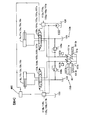
- FIG. 4 is a diagram schematically showing hydraulic circuits 150a and 150b for driving the first front work machine A and the second front work machine B.
- 101a and 101b are variable displacement hydraulic pumps for main pressure driven by the engine 40, and 102 is a pump for pilot pressure.
- 103a, 104a, 105a, 106a, and 107a are control valves that supply pressure oil to the swing cylinder 9a, boom cylinder 11a, arm cylinder 13a, work tool cylinder 15a, and grapple cylinder 19a of the first front work machine A, respectively. is there.
- the control valves 103a to 107a are controlled by the proportional control valves 113a, 114a, 115a, 116a, and 117a based on output signals generated by an operation control device (controller) 400, which will be described in detail later. That is, the proportional control valve 113a is the control valve 103a, the proportional control valve 114a is the control valve 104a, the proportional control valve 115a is the control valve 105a, the proportional control valve 116a is the control valve 106a, and the proportional control valve 117a is the control valve 107a. Control each one.
- Reference numeral 108a denotes a main relief valve that regulates the maximum pressure of the hydraulic circuit 150a related to the first front work machine A.
- the pressure oil discharged from the main pump 101a is supplied to each hydraulic cylinder via the control valves 103a to 107a.
- the pilot pressure oil discharged from the pilot pump 102 is supplied to the corresponding control valves 103a to 107a by the operation of the electromagnetic proportional valves 113a to 117a according to the output signal of the controller 400, The spool of the control valve is driven according to the operation amount of the operating device 50a.
- the control valves 103a to 107a supply the pressure oil discharged from the main pump 101a to the cylinders (actuators) 9a, 11a, 13a, 15a, 19a according to the drive amount of the spool, and drive the cylinders.
- the hydraulic circuit 150b that drives the cylinders (actuators) 9b, 11b, 13b, 15b, and 19b of the second front work machine B has the same configuration as the hydraulic circuit 150a according to the first front work machine A. The detailed explanation is omitted.
- the pressure oil discharged from the main pump 101a is supplied to the cylinders 9a, 11a, 13a, 15a and 19a of the first front work machine A, and is discharged from the main pump 101b.
- the oil is supplied to each cylinder 9b, 11b, 13b, 15b, 19b of the second front work machine B.
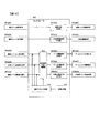
- FIG. 7 is a schematic diagram related to the operation control system in the first embodiment.
- Signals 401a (b) to 404a (b) that are input to the controller 400 are operation signals detected by each of the displacement detectors described above. That is, the operation arm operation signal 401a (b) is output from the operation arm displacement detector 57a (b).
- the operation lever up / down operation signal 402a (b) is output from the operation lever vertical displacement detector 581a (b).
- the operation lever front / rear operation signal 403a (b) is output from the operation lever front / rear direction displacement detector 582a (b).
- the operation lever rotation operation signal 404a (b) is output from the rotation lever displacement detector 59a (b).
- the operation switch operation signal 405a (b) is output from the operation switch displacement detector 60a (b).
- the operation lever selection switch signal 701 is output from the operation lever selection switch 61.
- the double-arm synchronous mode switch signal 702 is output from the double-arm synchronous mode switch 62.
- Signals 601a (b) to 605a (b) that are output from the controller 400 are the above-described swing cylinder 9a (b), boom cylinder 11a (b), arm cylinder 13a (b), work tool cylinder 15a (b), It is a drive signal which drives each grapple cylinder 19a (b). That is, the swing cylinder drive signal 601a (b) is output to the proportional control valve 113a (b) in FIG. 4, and the boom cylinder drive signal 602a (b) is output to the proportional control valve 114a (b) in FIG. The arm cylinder drive signal 603a (b) is output to the proportional control valve 115a (b) in FIG. The work tool cylinder drive signal 604a (b) is output to the proportional control valve 116a (b) in FIG. 4, and the work tool drive signal 605a (b) is output to the proportional control valve 117a (b) in FIG.
- the swing signal generation unit 501a (b) generates and outputs a swing cylinder drive signal 601a (b)
- the boom drive signal generation unit 502a (b) generates a boom cylinder drive signal 602a (b).
- the arm drive signal generator 503a (b) generates and outputs an arm cylinder drive signal 603a (b).
- the work tool rotation signal generation unit 504a (b) generates and outputs a work tool cylinder drive signal 604a (b)
- the work tool drive signal generation unit 505a (b) outputs the work tool drive signal 605a (b). Generate and output.
- FIG. 8 is a schematic diagram related to signal processing performed in each of the signal generators 501a (b) to 505a (b), and schematically shows the relationship between each operation signal described above and each drive signal described above.
- a cylinder speed command value proportional to the operation amount of the operation lever 54a (b) or the like is calculated as each drive signal. Note that a dead zone is set in order to define an operation amount at which the lever operation is effective.
- an input signal 701 is a signal indicating a setting state of the operation lever selection switch 61 and is output from the operation lever selection switch 61.
- the input signal 702 is a signal indicating the setting state of the double-arm synchronous mode switch 62 and is output from the double-arm synchronous mode switch 62.
- the setting states of the input signals 701 and 702 can be appropriately changed by the operator by operating the operation lever selection switch 61 and the double arm synchronous mode switch 62.
- An operation signal sharing calculation unit 801 described later receives an input signal 402a (b) to 404a (b) of an operation lever, an operation lever selection switch signal 701, and a double-arm synchronous mode switch signal 702, respectively.
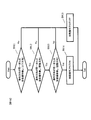
- FIG. 9 is a flowchart showing a processing flow of the operation signal common operation unit 801.
- an ignition switch not shown
- a program for performing the process shown in FIG. 9 is started and repeatedly executed by the operation signal common operation unit 801.
- a double-arm synchronous mode switch signal 702 indicating the setting state of the double-arm synchronous mode switch 62 is read to determine whether or not the operation mode is set to the double-arm synchronous mode.
- step S901 If the determination in step S901 is affirmative, that is, if the operation mode is set to the dual-arm synchronization mode and the dual-arm synchronization is permitted, the process proceeds to step S902.
- step S902 the operation lever selection switch signal 701 is read to determine whether the selection position of the operation lever selection switch 61 is the right operation device selection position or the left operation device selection position.
- step S902 If it is determined in step S902 that the selection position of the operation lever selection switch 61 is the right operation device selection position, the process proceeds to step S903, where the operation signal of the operation lever 54b is overwritten with the operation signal of the operation lever 54a.
- a process of overwriting the operation signal of the tool rotation lever 55b with the operation signal of the work tool rotation lever 55a is performed. Specifically, a process of replacing (sharing) the values of the input signals 402b to 404b with the values of the input signals 402a to 404a regardless of the values is performed. As a result, the operation lever up / down operation signal 402b is replaced with the value of the operation lever up / down operation signal 402a regardless of the value.
- the operation lever front / rear operation signal 403b is replaced with the value of the operation lever front / rear operation signal 403a.
- the operation lever rotation operation signal 404b is replaced with the value of the operation lever rotation operation signal 404a. That is, the operation lever up / down operation signal 402a, the operation lever front / rear operation signal 403a, and the operation lever rotation operation signal 404a are common signals for driving the left and right actuators with a common signal.
- step S903 When step S903 is executed, the process proceeds to step S905, and the operation signals after processing in step S903 are output to the signal generation units 502a to 504a and the signal generation units 502b to 504b. That is, the operation lever up / down operation signal 402a is output to the boom drive signal generation unit 502a. An operation lever front / rear operation signal 403a is output to the arm drive signal generation unit 503a. An operation lever rotation operation signal 404a is output to the work tool rotation signal generation unit 504a.
- an operation lever up / down operation signal 402a is output to the boom drive signal generation unit 502b instead of the operation lever up / down operation signal 402b.
- the arm drive signal generation unit 503b outputs an operation lever front / rear operation signal 403a.
- an operation lever rotation operation signal 404a is output to the work tool rotation signal generation unit 504b.
- step S902 If it is determined in step S902 that the selection position of the operation lever selection switch 61 is the left operation device selection position, the process proceeds to step S904, where the operation signal of the operation lever 54a is overwritten with the operation signal of the operation lever 54b.
- a process of overwriting the operation signal of the tool rotation lever 55a with the operation signal of the work tool rotation lever 55b is performed. Specifically, a process of replacing (making common) the values of the input signals 402a to 404a with the values of the input signals 402b to 404b regardless of the values. As a result, the operation lever up / down operation signal 402a is replaced with the value of the operation lever up / down operation signal 402b regardless of the value.
- the operation lever front / rear operation signal 403a is replaced with the value of the operation lever front / rear operation signal 403b regardless of the value. Regardless of its value, the operation lever rotation operation signal 404a is replaced with the value of the operation lever rotation operation signal 404b. That is, the operation lever up / down operation signal 402b, the operation lever front / rear operation signal 403b, and the operation lever rotation operation signal 404b are common signals for driving the left and right actuators with a common signal.
- step S904 the process proceeds to step S905, and the operation signals after processing in step S904 are output to the signal generation units 502a to 504a and the signal generation units 502b to 504b. That is, an operation lever up / down operation signal 402b is output to the boom drive signal generation unit 502a instead of the operation lever up / down operation signal 402a. Instead of the operation lever front / rear operation signal 403a, the arm drive signal generation unit 503a outputs an operation lever front / rear operation signal 403b. Instead of the operation lever rotation operation signal 404a, an operation lever rotation operation signal 404b is output to the work tool rotation signal generation unit 504a.
- the operation lever up / down operation signal 402b is output to the boom drive signal generation unit 502b.
- An operation lever front / rear operation signal 403b is output to the arm drive signal generation unit 503b.
- An operation lever rotation operation signal 404b is output to the work tool rotation signal generation unit 504b.
- step S901 determines whether the operation mode is set to the normal mode and the dual-arm synchronization is permitted. If the determination in step S901 is negative, that is, if the operation mode is set to the normal mode and the dual-arm synchronization is not permitted, the process proceeds to step S905. That is, when the determination in step S901 is negative, the operation signal overwriting process performed in step S903 or step S904 is not performed, and the input signals 402a to 404a are output to the corresponding signal generators 502a to 504a.
- the input signals 402b to 404b are output to the corresponding signal generators 502b to 504b.
- an operation lever up / down operation signal 402a is output to the boom drive signal generation unit 502a.
- An operation lever front / rear operation signal 403a is output to the arm drive signal generation unit 503a.
- An operation lever rotation operation signal 404a is output to the work tool rotation signal generation unit 504a.
- the operation lever up / down operation signal 402b is output to the boom drive signal generation unit 502b.
- An operation lever front / rear operation signal 403b is output to the arm drive signal generation unit 503b.
- An operation lever rotation operation signal 404b is output to the work tool rotation signal generation unit 504b.
- the operation mode is set to the double arm synchronous mode and the right operation device selection position is selected by the operation lever selection switch 61, the above-described steps are performed.
- the process of S903 is performed.
- it is possible to synchronize the two arms specifically, to synchronize the booms 10a and 10b and the arms 12a and 12b of the first front work machine A and the second front work machine B by operating the operation lever 54a. It becomes.
- by simply operating the work implement rotating lever 55a it is possible to perform the double-arm synchronous operation, specifically, the synchronous operation of the grapples 20a and 20b of the first front work machine A and the second front work machine B.
- step S904 is performed. Processing is performed.
- step S903 and step S904 when the operation mode is set to the normal mode, the above-described processing of step S903 and step S904 is not performed. Therefore, in this case, a conventional operation in which the two arms are operated using the corresponding operation levers 54a and 54b and the work tool rotation levers 55a and 55b can be performed.
- the posture (initial posture) of the first front work machine A at the start of the above-described double-arm synchronous operation and the posture (initial posture) of the second front work machine B are different, The relative position between the grapples 20a and 20b changes. Therefore, there is a possibility that the work object grasped by the grapples 20a and 20b may be damaged by the synchronous operation of the two arms.
- the work machine 200 of the first embodiment when the work object is to be gripped by the left and right grapples 20a and 20b, the first front work machine A and the second front work machine B naturally have substantially the same posture. It becomes.
- the posture of the first front work machine A is such that the swing angle of the swing post 7a with respect to the upper swing body 3, the pivot angle of the boom 10a with respect to the swing post 7a, the pivot angle of the arm 12a with respect to the boom 10a, and the arm 12a. It is defined by the rotation angle of the first work tool 14a.
- the posture of the second front work machine B is such that the swing angle of the swing post 7b with respect to the upper swing body 3, the pivot angle of the boom 10b with respect to the swing post 7b, the pivot angle of the arm 12b with respect to the boom 10a, and the arm 12b. It is defined by the rotation angle of the second work tool 14b.
- the initial posture of the first front work machine A in the normal work is substantially the same. Therefore, whether or not the initial posture of the first front work machine A and the initial posture of the second front work machine B are substantially the same on the work machine 200 side as a condition for starting the double-arm synchronous operation in normal work. The necessity to judge is low. Therefore, in the work machine 200 according to the first embodiment, the initial postures of the first front work machine A and the second front work machine B are not listed as conditions for starting the double-arm synchronous operation.
- the work machine 200 it was confirmed by visual observation by an operator or a ground worker that the posture of the first front work machine A and the posture of the second front work machine B were substantially the same. It is desirable to start the dual arm synchronization operation above.
- the work machine 200 has the following operational effects.
- a common signal (common drive command) for driving with the operation signal common operation unit 801 is generated.
- the synchronous operation of the 1st front work machine A and the 2nd front work machine B is realizable by simple structure, and the double arm work machine applicable to a wide range of work can be provided at low cost. That is, since the two-arm synchronous operation can be performed without modifying the first front work machine A and the second front work machine B, an increase in cost can be suppressed.
- the operation mode can be switched by operating the double-arm synchronous mode switch 62 by the operator.
- the operator's intention to switch the operation mode can be reliably reflected, so that an operation in accordance with the operator's intention is possible, and the operability is improved.
- FIGS. 10 to 13 With reference to FIGS. 10 to 13, a second embodiment of the double-armed work machine according to the present invention will be described.
- the same components as those in the first embodiment are denoted by the same reference numerals, and differences will mainly be described. Points that are not particularly described are the same as those in the first embodiment.
- the first embodiment is mainly based on the point of determining whether or not the two-arm synchronous operation is possible based on the operation directions of the operation levers 54a and 54b and the rotation levers 55a and 55b. Different from form.
- FIG. 10 is a diagram illustrating an operating device according to the second embodiment.
- the operation lever selection switch 61 and the double-arm synchronous mode switch 62 are not provided.
- the displacement amount (operation amount) between the right operation lever 54a and the left operation lever 54b is reduced.
- the left and right booms 10a and 10b and the left and right arms 12a and 12b are simultaneously swung in accordance with the operation amount of the larger operation lever. Specifically, the left and right booms 10a and 10b are simultaneously swung according to the operation amount of the operation lever with the larger amount of operation in the vertical direction between the right operation lever 54a and the left operation lever 54b.
- the left and right arms 12a and 12b are simultaneously swung according to the operation amount of the operation lever with the larger operation amount in the front-rear direction between the right operation lever 54a and the left operation lever 54b. Further, the left and right working tools 14a and 14b are simultaneously swung according to the turning amount of the turning lever with the larger displacement amount (turning amount) between the right turning lever 55a and the left turning lever 55b.
- FIG. 11 is a schematic diagram related to the operation control system in the second embodiment.
- the controller 400 is provided with an operation direction determination unit 810 and an operation signal sharing calculation unit 811.
- the operation direction determination unit 810 receives input signals 402a (b) to 404a (b) such as operation levers.
- the operation signal sharing calculation unit 811 receives input signals 402a (b) to 404a (b) of the operation lever and the determination result of the operation direction determination unit 810.
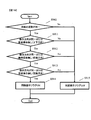
- FIG. 12 is a flowchart illustrating a processing flow of the operation direction determination unit 810.
- an ignition switch not shown
- a program for performing the process shown in FIG. 12 is started and repeatedly executed by the operation direction determination unit 810. Note that this program is a program for determining whether or not all of the above conditions (2-1) to (2-3) are satisfied.
- step S911 based on the operation lever up / down operation signal 402a and the operation lever up / down operation signal 402b, it is determined whether or not the above condition (2-1) is satisfied.
- the above condition (2-1) is satisfied, that is, the right operation lever 54a and the left operation lever 54b have the same operation direction in the vertical direction, or the right operation lever 54a and the left operation lever 54b are both If it is determined that the vertical operation has not been performed, the process proceeds to step S912.
- step S912 it is determined whether or not the above condition (2-2) is satisfied based on the operation lever front / rear operation signal 403a and the operation lever front / rear operation signal 403b.
- the above condition (2-2) is satisfied, that is, the right operation lever 54a and the left operation lever 54b have the same operation direction in the front-rear direction, or the right operation lever 54a and the left operation lever 54b are both If it is determined that the operation is not performed in the front-rear direction, the process proceeds to step S913.
- step S913 it is determined whether or not the above condition (2-3) is satisfied based on the operation lever rotation operation signal 404a and the operation lever rotation operation signal 404b.
- the above condition (2-3) is satisfied, that is, the operation direction (rotation direction) is the same between the right rotation lever 55a and the left rotation lever 55b, or the right rotation lever 55a and the left rotation If it is determined that both levers 55b are not rotated, the process proceeds to step S914.
- step S914 it is assumed that a synchronous operation is being performed, and a process for turning on the synchronous operation flag is performed.
- step S914 the program is terminated.
- step S911 If a negative determination is made in step S911, a negative determination is made in step S912, or a negative determination is made in step S913, the process proceeds to step S915, in which it is considered that the synchronous operation is not performed, and the process of setting the synchronous operation flag to OFF Is done.
- step S915 the program is terminated.
- the operation direction determination unit 810 determines whether or not the operation directions of the right operation lever 54a and the left operation lever 54b are the same, and the operation directions of the right rotation lever 55a and the left rotation lever 55b. Also function as a synchronous operation determination unit for determining whether or not the same.
- FIG. 13 is a flowchart showing the processing flow of the operation signal common operation unit 811.
- an ignition switch not shown
- a program for performing the process shown in FIG. 13 is started and repeatedly executed by the operation signal common operation unit 811. If it is determined in step S921 that the synchronous operation flag that is the processing result of the operation direction determination unit 810 is ON, the process proceeds to step S922.
- step S922 the amount of operation in the vertical direction of the operation lever 54a and the operation lever 54b is compared. If the operation amount in the vertical direction of the right operation lever 54a is larger than the operation amount in the vertical direction of the left operation lever 54b, the process proceeds to step S923. Otherwise, the process proceeds to step S924. In step S923, the process of overwriting the operation lever up / down operation signal 402b of the operation lever 54b with the operation lever up / down operation signal 402a of the operation lever 54a, specifically, the value of the input signal 402b is changed to the input signal regardless of the value. A process of replacing (sharing) with the value of 402a is performed.
- step S924 the process of overwriting the operation lever up / down operation signal 402a of the operation lever 54a with the operation lever up / down operation signal 402b of the operation lever 54b, specifically, the value of the input signal 402a is set regardless of the value. A process of replacing (sharing) with the value of the input signal 402b is performed.
- step S923 or step S924 the process proceeds to step S925.
- step S925 the amount of operation in the front-rear direction of the operation lever 54a and the operation lever 54b is compared. If the operation amount in the front-rear direction of the right operation lever 54a is larger than the operation amount in the front-rear direction of the left operation lever 54b, the process proceeds to step S926. Otherwise, the process proceeds to step S927.
- step S926 the operation lever front / rear operation signal 403b of the operation lever 54b is overwritten with the operation lever front / rear operation signal 403a of the operation lever 54a. Specifically, the value of the input signal 403b is changed to the input signal regardless of the value. A process of replacing (sharing) with the value of 403a is performed.
- step S927 the operation lever front / rear operation signal 403a of the operation lever 54a is overwritten with the operation lever front / rear operation signal 403b of the operation lever 54b. Specifically, the value of the input signal 403a is set regardless of the value. A process of replacing (sharing) with the value of the input signal 403b is performed.
- step S926 or step S927 the process proceeds to step S928.
- step S928 the magnitudes of the operation amounts (rotation amounts) of the work tool rotation lever 55a and the work tool rotation lever 55b are compared. If the operation amount of the right work tool rotation lever 55a is larger than the operation amount of the left work tool rotation lever 55b, the process proceeds to step S929; otherwise, the process proceeds to step S931.
- step S929 the operation lever rotation operation signal 404b of the work tool rotation lever 55b is overwritten with the operation lever rotation operation signal 404a of the work tool rotation lever 55a. Specifically, the value of the input signal 404b is Regardless of the value, a process of replacing (sharing) with the value of the input signal 404a is performed.
- step S931 the operation lever rotation operation signal 404a of the work tool rotation lever 55a is overwritten with the operation lever rotation operation signal 403b of the work tool rotation lever 55b, specifically, the value of the input signal 404a. Is replaced (shared) with the value of the input signal 404b regardless of the value.
- step S929 or step S931 the process proceeds to step S932, and each operation signal after the processing in each step described above is output to each signal generation unit 502a to 504a and each signal generation unit 502b to 504b. That is, the boom drive signal generators 502a and 502b output a signal having a larger value by comparing the operation lever up / down operation signal 402a and the operation lever up / down operation signal 402b.
- the arm drive signal generators 503a and 503b output a signal having a larger value by comparing the operation lever front / rear operation signal 403a and the operation lever front / rear operation signal 403b.
- the work tool rotation signal generation units 504a and 504b output a signal having a larger value by comparing the operation lever rotation operation signal 404a and the operation lever rotation operation signal 404b.
- step S921 If it is determined in step S921 that the synchronous operation flag, which is the processing result of the operation direction determination unit 810, is OFF, the process proceeds to step S932.
- the operation signal overwriting process performed in each step described above is not performed, the input signals 402a to 404a are output to the corresponding signal generators 502a to 504a, and the input signals 402b to 404b are supported. Output to the signal generators 502b to 504b.
- an operation lever up / down operation signal 402a is output to the boom drive signal generation unit 502a.
- An operation lever front / rear operation signal 403a is output to the arm drive signal generation unit 503a.
- An operation lever rotation operation signal 404a is output to the work tool rotation signal generation unit 504a.
- the operation lever up / down operation signal 402b is output to the boom drive signal generation unit 502b.
- An operation lever front / rear operation signal 403b is output to the arm drive signal generation unit 503b.
- An operation lever rotation operation signal 404b is output to the work tool rotation signal generation unit 504b.
- the operation lever 54a and the operation lever 54b are operated in substantially the same direction, and the rotation lever 55a and the rotation lever 55b are operated in the same direction.
- the dual-arm synchronous operation can be performed by taking into account the operator's intention of the dual-arm synchronous operation. That is, the double-arm synchronization operation is assisted only when the operator tries to synchronize the two arms.
- the left and right booms 10a and 10b and the arms 12a and 12b are simultaneously swung according to the operation amount of the operation lever having the larger operation amount in the vertical direction and the front and rear direction of the left and right operation levers 54a and 54b.
- the work tools 14a and 14b are simultaneously swung in accordance with the rotation amount of the rotation lever with the larger rotation amount of the left and right rotation levers 55a and 55b.
- the conventional operation in which the two arms are operated using the corresponding operation levers 54a and 54b and the work tool rotation levers 55a and 55b can be performed.
- the work machine 200 according to the second embodiment described above has the following effects in addition to the effects provided by the work machine 200 according to the first embodiment.
- the left and right operation amount, the operation amount with the larger rotation amount, and the rotation amount are effective in the dual arm synchronous operation and are reflected in the movement amount of the two arms.
- the operation becomes easy and the work efficiency is improved.
- the left and right booms 10a and 10b, the arms 12a and 12b, and the work tools 14a and 14b are simultaneously swung based on the average value of the displacement amount (rotation amount) between the moving lever 55a and the left rotation lever 55b.
- the second embodiment Different from the second embodiment.
- the operating device in the third embodiment is the same as the operating device in the second embodiment.
- the double-arm synchronization is performed. Operation becomes possible.
- the displacement amount (operation amount) between the right operation lever 54a and the left operation lever 54b.
- the right and left booms 10a and 10b, arms 12a and 12b, and working tools 14a and 14b, according to the average value of the left and right rotation levers 55a and 55b. Are simultaneously swung.
- the left and right booms 10a and 10b are simultaneously swung according to the average value of the operation amount in the vertical direction of the right operation lever 54a and the left operation lever 54b. Then, the left and right arms 12a and 12b are simultaneously swung in accordance with the average value of the operation amounts in the front-rear direction of the right operation lever 54a and the left operation lever 54b. Further, as described above, the left and right work tools 14a and 14b are simultaneously swung according to the average value of the rotation amounts of the right rotation lever 55a and the left rotation lever 55b.
- FIG. 14 is a flowchart illustrating a processing flow of the operation signal commonization operation unit 811 according to the third embodiment.
- an ignition switch not shown
- Step S921 is the same as step S921 in FIG. 13 of the second embodiment.
- step S921 is executed, the process proceeds to step S941.
- step S941 the average value of the operation amount of the right operation lever 54a and the left operation lever 54b, and the average value of the rotation amount of the right rotation lever 55a and the left rotation lever 55b (each average value is calculated).
- an average manipulated variable the average operation amount in the vertical direction of the right operation lever 54a and the left operation lever 54b, the average operation amount in the front-rear direction of the right operation lever 54a and the left operation lever 54b, and the right turn An average operation amount between the moving lever 55a and the left turning lever 55b is calculated.
- step S941 the process proceeds to step S942, where the value of the operation signal corresponding to each average operation amount calculated in step S941 is calculated, and the corresponding input signals 402a to 404a and input signals 402b to 404b are overwritten. Is done. Specifically, a process is performed in which the values of the input signals 402a to 404a and the values of the input signals 402b to 404b are replaced (shared) with the values of the operation signals corresponding to the respective average operation amounts regardless of the values.
- the operation lever up / down operation signals 402a and 402b are replaced with the value of the operation signal corresponding to the average operation amount of the operation levers 54a and 54b in the up / down direction regardless of the value.
- the operation lever front / rear operation signals 403a and 403b are replaced with the value of the operation signal corresponding to the average operation amount in the front / rear direction of the operation levers 54a and 54b.
- the operation lever rotation operation signals 404a and 404b are replaced with the value of the operation signal corresponding to the average operation amount of the rotation levers 55a and 55b.
- step S942 the process proceeds to step S943, and the operation signals after the processing in step S942 described above are output to the signal generators 502a to 504a and the signal generators 502b to 504b. That is, an operation signal corresponding to the average operation amount in the vertical direction of the operation levers 54a and 54b is output to the boom drive signal generation units 502a and 502b.
- the arm drive signal generation units 503a and 503b output operation signals corresponding to the average operation amount in the front-rear direction of the operation levers 54a and 54b.
- An operation signal corresponding to the average operation amount of the rotation levers 55a and 55b is output to the work tool rotation signal generation units 504a and 504b.
- step S921 If it is determined in step S921 that the synchronous operation flag, which is the processing result of the operation direction determination unit 810, is OFF, the process proceeds to step S943.
- the operation signal overwriting process performed in step S942 described above is not performed, the input signals 402a to 404a are output to the corresponding signal generation units 502a to 504a, and the input signals 402b to 404b correspond. Output to the signal generators 502b to 504b.
- an operation lever up / down operation signal 402a is output to the boom drive signal generation unit 502a.
- An operation lever front / rear operation signal 403a is output to the arm drive signal generation unit 503a.
- An operation lever rotation operation signal 404a is output to the work tool rotation signal generation unit 504a.
- the operation lever up / down operation signal 402b is output to the boom drive signal generation unit 502b.
- An operation lever front / rear operation signal 403b is output to the arm drive signal generation unit 503b.
- An operation lever rotation operation signal 404b is output to the work tool rotation signal generation unit 504b.
- the operation lever 54a and the operation lever 54b are operated in substantially the same direction, and the rotation lever 55a and the rotation lever 55b are operated in the same direction. Synchronous operation of both arms is possible. That is, the double-arm synchronization operation is assisted only when the operator tries to synchronize the two arms. At this time, the left and right booms 10a and 10b, the arms 12a and 12b, and the work tools 14a and 14b are simultaneously swung in accordance with the average operation amounts of the left and right operation levers 54a and 54b and the left and right rotation levers 55a and 55b. . In other cases, the conventional operation in which the two arms are operated using the corresponding operation levers 54a and 54b and the work tool rotation levers 55a and 55b can be performed.
- the work machine 200 according to the third embodiment described above has the following effects in addition to the effects provided by the work machine 200 according to the first and second embodiments. That is, the left and right booms 10a and 10b, the arms 12a and 12b, and the work tools 14a and 14b correspond to the average operation amount of the left and right operation levers 54a and 54b and the average operation amount of the left and right rotation levers 55a and 55b. Since it is swung at the same time, when the operator wants to control the movement amount of the two arms during the synchronous operation using the operation amounts of both arms, the operation becomes easy and the work efficiency is improved.
- FIGS. 15 and 16 a fourth embodiment of the double-armed work machine according to the present invention will be described.
- the same components as those in the first to third embodiments are denoted by the same reference numerals, and differences will mainly be described. Points that are not particularly described are the same as those in the third embodiment.
- the operating device in the fourth embodiment is the same as the operating device in the second and third embodiments.
- the right operation lever 54a and the left operation lever are the same as in the third embodiment.
- FIG. 15 is a schematic diagram related to the operation control system in the fourth embodiment.
- the controller 400 is provided with an operation vector determination unit 820 and a threshold setting unit 821 instead of the operation direction determination unit 810 in the third embodiment.
- the operation vector determination unit 820 receives input signals 402a (b) to 404a (b) such as operation levers. The processing in the operation vector determination unit 820 will be described later.
- the threshold setting unit 821 sets a threshold for determining whether or not the operation vectors of the right operation lever 54a and the rotation lever 55a and the left operation lever 54b and the rotation lever 55b are substantially the same. For example, a threshold set in advance at the factory when the work machine 200 is shipped is stored. The threshold value can be arbitrarily set to a desired value, and the setting can be performed using an external setting device such as a personal computer.
- the threshold value stored in the threshold value setting unit 821 includes, for example, a threshold value related to a difference in the vertical operation vector between the operation lever 54a and the control lever 54b, and a forward / backward operation vector between the control lever 54a and the control lever 54b.
- the threshold value regarding the difference and the threshold value regarding the difference between the operation vectors of the rotation lever 55a and the rotation lever 55b are included.
- FIG. 16 is a flowchart illustrating the processing flow of the operation vector determination unit 820.
- an ignition switch not shown
- This program is a program for determining whether or not all of the above conditions (4-1) to (4-3) are satisfied.
- step S951 it is determined whether or not the above condition (4-1) is satisfied based on the operation lever up / down operation signal 402a and the operation lever up / down operation signal 402b. Satisfy the above condition (4-1), that is, the difference in the vertical operation vector between the right operating lever 54a and the left operating lever 54b is within a predetermined threshold, or the right operating lever 54a and the left operating lever 54b If it is determined that both the operation levers 54b are not operated in the vertical direction, the process proceeds to step S952.
- step S952 whether or not the above condition (4-2) is satisfied is determined based on the operation lever front / rear operation signal 403a and the operation lever front / rear operation signal 403b.
- the above condition (4-2) is satisfied, that is, the difference between the operation vectors in the front-rear direction between the right operation lever 54a and the left operation lever 54b is within a predetermined threshold, or the right operation lever 54a and the left operation lever 54b If it is determined that both the operation levers 54b are not operated in the front-rear direction, the process proceeds to step S953.
- step S953 it is determined whether or not the above condition (4-3) is satisfied based on the operation lever rotation operation signal 404a and the operation lever rotation operation signal 404b.
- the above condition (4-3) is satisfied, that is, the difference between the operation vectors of the right rotation lever 55a and the left rotation lever 55b is within a predetermined threshold, or the right rotation lever 55a and the left rotation lever 55b If it is determined that both the turning levers 55b are not turned, the process proceeds to step S954.
- step S954 the operation vectors of the operation levers 54a and 54b and the operation vectors of the rotation levers 55a and 55b are substantially the same on the left and right, and it is assumed that the synchronization operation is performed, and the process of turning on the synchronization operation flag is performed. Done.
- step S954 is executed, this program is terminated.
- step S951 is negatively determined, step S952 is negatively determined, or step S953 is negatively determined, the process proceeds to step S955.
- step S955 when at least one of the operation vectors of the operation levers 54a and 54b and the operation vectors of the rotation levers 55a and 55b is operated and the difference between the operation vectors is larger than a predetermined threshold value and the left and right are synchronized, Assuming that no operation has been performed, processing for turning off the synchronous operation flag is performed.
- step S955 is executed, the program is terminated.
- the operation vectors of the operation lever 54a and the operation lever 54b are substantially the same, and the operation vectors of the rotation lever 55a and the rotation lever 55b are substantially the same.
- the double-arm synchronization operation is assisted only when the operator tries to synchronize the two arms.
- the left and right booms 10a and 10b, the arms 12a and 12b, and the work tools 14a and 14b are simultaneously swung in accordance with the average operation amounts of the left and right operation levers 54a and 54b and the left and right rotation levers 55a and 55b.
- the conventional operation in which the two arms are operated using the corresponding operation levers 54a and 54b and the work tool rotation levers 55a and 55b can be performed.
- the work machine 200 according to the fourth embodiment described above has the following effects in addition to the effects provided by the work machine 200 according to the first to third embodiments. That is, when the operation vectors of the operation lever 54a and the operation lever 54b are substantially the same, or when the operation vectors of the rotation lever 55a and the rotation lever 55b are substantially the same, the two-arm synchronous operation can be performed. Become. Therefore, the accuracy of determining whether or not the operator intends to perform a dual-arm synchronization operation is improved, and even if there is no operation mode switching operation, the dual-arm synchronization operation can be performed more accurately. Efficiency is improved.
- the operating device in the fifth embodiment is the same as the operating device in the second to fourth embodiments.
- the working machine 200 of the fifth embodiment is provided with angle sensors 131a to 134a and 131b to 134b.
- the angle sensor 131a detects the rotation angle of the boom 10a with respect to the swing post 7a (see arrow Y in FIG. 17, hereinafter simply referred to as the boom angle a).
- the angle sensor 132a detects the rotation angle of the arm 12a with respect to the boom 10a (see arrow X in FIG. 17, hereinafter simply referred to as the arm angle a).
- the angle sensor 133a detects the rotation angle of the first work tool 14a with respect to the arm 12a (see arrow Z in FIG. 17, hereinafter, simply referred to as work tool angle a).
- the angle sensor 134a detects the swing angle of the swing post 7a with respect to the upper swing body 3 (see arrow W in FIG. 17, hereinafter simply referred to as swing angle a).
- the angle sensor 131b detects the rotation angle of the boom 10b with respect to the swing post 7b (see arrow Y in FIG. 17, hereinafter simply referred to as the boom angle b).
- the angle sensor 132b detects the rotation angle of the arm 12b with respect to the boom 10b (see arrow X in FIG. 17, hereinafter simply referred to as the arm angle b).
- the angle sensor 133b detects the rotation angle of the second work tool 14b with respect to the arm 12b (see arrow Z in FIG. 17, hereinafter simply referred to as work tool angle b).
- the angle sensor 134b detects the swing angle of the swing post 7b with respect to the upper swing body 3 (see arrow W in FIG. 17, hereinafter simply referred to as swing angle b).
- FIG. 18 is a schematic diagram related to the operation control system in the fifth embodiment.
- the controller 400 is provided with an attitude determination unit 830 and a threshold setting unit 831.
- Posture detection signals 710a and 710b are captured in the posture determination unit 830.
- the attitude detection signal 710a is a general term for angle detection signals output from the angle sensors 131a to 134a.
- the posture detection signal 710a includes a boom angle detection signal 711a output from the angle sensor 131a, an arm angle detection signal 712a output from the angle sensor 132a, and a work implement angle detection signal 713a output from the angle sensor 133a. And a swing angle detection signal 714a output from the angle sensor 134a.
- the attitude detection signal 710b is a general term for angle detection signals output from the angle sensors 131b to 133b.
- the posture detection signal 710b includes a boom angle detection signal 711b output from the angle sensor 131b, an arm angle detection signal 712b output from the angle sensor 132b, a work tool angle detection signal 713b output from the angle sensor 133b, And a swing angle detection signal 714b output from the angle sensor 134b.
- the processing in the posture determination unit 830 will be described later.
- the threshold setting unit 831 is a setting unit that sets a threshold for determining whether or not the initial posture of the first front work machine A and the initial posture of the second front work machine B are substantially the same.
- a threshold value preset in the factory at the time of shipment of the machine 200 is stored.
- the threshold value can be arbitrarily set to a desired value, and the setting can be performed using an external setting device such as a personal computer.
- the threshold value stored in the threshold setting unit 831 includes, for example, a threshold value regarding the difference between the boom angle a and the boom angle b, a threshold value regarding the difference between the arm angle a and the arm angle b, and the work tool angle a and the work tool angle b.
- a threshold value regarding a difference (deviation) from the swing angle b is included.
- the posture determination unit 830 determines whether or not the initial posture of the first front work machine A and the initial posture of the second front work machine B are substantially the same based on the posture detection signals 710a and 710b. Specifically, when all of the following conditions (5-1) to (5-5) are satisfied, the initial posture of the first front work machine A and the initial posture of the second front work machine B are substantially the same. Judge that there is. (5-1) The difference between the boom angle a and the boom angle b is within a predetermined threshold. (5-2) The difference between the arm angle a and the arm angle b is within a predetermined threshold. (5-3) The difference between the work tool angle a and the work tool angle b is within a predetermined threshold. (5-4) The deviation between the front-rear direction of the work machine 200 and the swing angle a is within a predetermined threshold. (5-5) The deviation between the front-rear direction of the work machine 200 and the swing angle b is within a predetermined threshold.
- FIG. 19 is a flowchart illustrating a processing flow of the operation direction determination unit 810.
- step S961 it is determined whether or not the posture determination unit 830 determines that the initial posture of the first front work machine A and the initial posture of the second front work machine B are substantially the same. That is, it is determined whether or not the posture determination unit 830 determines that all of the above conditions (5-1) to (5-5) are satisfied. If a positive determination is made in step S961, the process proceeds to step S911. If a negative determination is made in step S961, the process proceeds to step S915. Thereafter, steps S911 to S915 are the same as the processing flow of the operation direction determination unit 810 in the second embodiment shown in FIG.
- the two-arm synchronous operation is performed only when the initial posture of the first front work machine A and the initial posture of the second front work machine B are substantially the same. It becomes possible.
- the work machine 200 according to the fifth embodiment described above has the following effects in addition to the effects provided by the work machine 200 according to the first to fourth embodiments. That is, only when the initial posture of the first front work machine A and the initial posture of the second front work machine B are substantially the same, the dual-arm synchronization operation is possible. It is possible to prevent the synchronization operation from being performed. Therefore, it is possible to provide a work machine suitable for work that transports work objects in parallel as shown in FIG.
- FIG. 21 is a diagram illustrating an operating device according to the sixth embodiment.
- the double-arm synchronous operation assist permission switch 63 is provided, for example, near the tip of the operation arm 52a.
- the double-arm synchronous operation assist permission switch 63 is used when the double-arm synchronous operation assist permission switch 63 satisfies all the conditions (2-1) to (2-3) for enabling the dual-arm synchronous operation in the second embodiment.
- the switch is operated by an operator to select whether or not the synchronization operation can be performed (whether or not the assist of the double-arm synchronization operation is permitted).
- the double-arm synchronous operation assist permission switch 63 outputs a synchronous operation assist permission signal 720 to an operation direction determination unit 840 to be described later when operated so as to permit the assist of the double-arm synchronous operation.
- the right operation lever 54a and the left operation lever 54a are The left and right booms 10a and 10b and the left and right arms 12a and 12b are simultaneously swung in accordance with the operation amount of the operation lever having a larger displacement amount (operation amount) with the operation lever 54b.
- FIG. 22 is a schematic diagram related to the operation control system in the sixth embodiment.
- the controller 400 is provided with an operation direction determination unit 840 instead of the operation direction determination unit 810 of the second embodiment.
- the operation direction determination unit 810 receives the input signals 402a (b) to 404a (b) of the operation lever and the like, and the synchronous operation assist permission signal 720 output from the double arm synchronous operation assist permission switch 63.
- FIG. 23 is a flowchart illustrating the processing flow of the operation direction determination unit 840.
- step S971 it is determined whether or not the synchronous operation assist permission signal 720 output from the double-arm synchronous operation assist permission switch 63 is received. That is, it is determined whether or not the above condition (6-1) is satisfied. If a positive determination is made in step S971, the process proceeds to step S911. If a negative determination is made in step S971, the process proceeds to step S915. Thereafter, each step from step S911 to step S915 is a processing flow for determining whether or not the condition (6-2) described above is satisfied, and the operation direction determination unit 810 in the second embodiment shown in FIG. The processing flow is the same as that of FIG.
- the double-arm synchronous operation is performed only when the double-arm synchronous operation assist permission switch 63 is operated by the operator so as to permit the double-arm synchronous operation assist.
- the operation direction determination unit 840 based on the synchronous operation assist permission signal 720, the operation direction determination unit 840 generates and outputs a common drive command for whether or not to permit the dual-arm synchronous operation, that is, the dual-arm synchronous operation. It also functions as a common drive command generation permission unit that permits or prohibits the operation.
- the work machine 200 according to the sixth embodiment described above has the following effects in addition to the effects provided by the work machine 200 according to the first to fifth embodiments. That is, the function of the double-arm synchronization operation can be temporarily stopped when the assistance of the double-arm synchronization operation is completely unnecessary. Therefore, it is possible to provide a work machine that can handle a wider range of work.
- the operation instructions of the booms 10a and 10b, the arms 12a and 12b, and the work tools 14a and 14b are instructed to rotate the horizontal operation levers 54a and 54b and around the operation levers 54a and 54b.
- the present invention is not limited to this.
- the operating device can appropriately set the operating speed of each of the front work machines A and B, an operating device other than the horizontal operating lever and the rotating lever may be used.
- the arrangement position is not limited to the above-described arrangement position.
- the common processing for the three operation signals of the operation lever up / down operation signal 402a (b), the operation lever front / rear operation signal 403a (b), and the operation lever rotation operation signal 404a (b) is performed.
- the present invention is not limited to this. You may comprise so that the process which makes common about at least 1 set of operation signal of 3 sets of operation signals mentioned above may be performed.
- the operation switch operation signal 405a (b) may be configured to perform a common process.
- the controller 400 is configured so that the swinging cylinder drive signals 601a and 601b are not output by the swinging signal generation units 501a and 501b even when the operation arm operation signals 401a and 401b are input during the synchronous operation of the two arms. May be.
- the amount of movement of the two arms during the synchronization operation is controlled based on the average operation amount of the left and right operation levers, as in the third embodiment described above.
- the present invention is not limited to this.
- the amount of movement of the two arms during the synchronization operation based on the operation amount of the operation lever having the larger operation amount among the left and right operation levers, as in the second embodiment. You may comprise so that it may control.
- the amount of movement of the two arms during the synchronization operation is determined based on the average operation amount of the left and right operation levers as in the third embodiment described above. You may comprise so that it may control. Furthermore, in the second and fourth to sixth embodiments described above, the amount of movement of the two arms during the synchronization operation is determined based on the operation amount of the operation lever with the smaller operation amount among the left and right operation levers. You may comprise so that it may control.
- the input signal 402a (b) to 404a (b) of the operation lever or the like is processed by the operation signal commoning operation unit 801, and is shared by the operation signal commoning operation unit 801.
- the operation signals are output to the signal generators 502a to 504a and the signal generators 502b to 504b so that the two arms are driven in synchronization.
- the present invention is not limited to this.
- input signals 402a (b) to 404a (b) from the operation lever or the like are directly input to the signal generators 502a to 504a and the signal generators 502b to 504b, and the signal generators 502a to 504a and the signal generators are input.
- a process of sharing the drive signals 602a (b) to 604a (b) may be performed in 502b to 504b. Then, the dual arms may be driven in synchronization by outputting the drive signals 602a (b) to 604a (b) after the common processing is performed.
- You may combine each embodiment and modification which were mentioned above, respectively. For example, the fifth embodiment and the sixth embodiment described above may be combined. Thereby, the initial posture of the first front work machine A and the initial posture of the second front work machine B are substantially the same, and the double-arm synchronous operation assist permission switch 63 allows the operator to assist the double-arm synchronous operation. Only when the two arms are operated, the synchronous operation of the two arms is possible.
- the double-arm synchronous operation assist permission switch 63 permits the dual-arm synchronous operation assist by the operator. When not operated, it is possible to prevent the double-arm synchronization operation from being performed.
- this invention is not limited to the thing of embodiment mentioned above at all,
- the second driving device that drives the second front work machine and the second attachment, and the first and second driving commands are input, and a common driving command that drives the first and second driving devices is generated.
- a two-arm type work machine having various structures, characterized in that it includes a drive command output device that outputs the drive command.
Landscapes
- Engineering & Computer Science (AREA)
- Structural Engineering (AREA)
- Mining & Mineral Resources (AREA)
- Civil Engineering (AREA)
- General Engineering & Computer Science (AREA)
- Mechanical Engineering (AREA)
- Robotics (AREA)
- Physics & Mathematics (AREA)
- Fluid Mechanics (AREA)
- Operation Control Of Excavators (AREA)
- Component Parts Of Construction Machinery (AREA)
- Manipulator (AREA)
Priority Applications (4)
| Application Number | Priority Date | Filing Date | Title |
|---|---|---|---|
| JP2013558738A JP5957473B2 (ja) | 2012-02-15 | 2013-02-14 | 双腕型作業機械 |
| CN201380009681.1A CN104114774B (zh) | 2012-02-15 | 2013-02-14 | 双臂式作业机械 |
| US14/378,824 US9458602B2 (en) | 2012-02-15 | 2013-02-14 | Dual-arm work machine |
| EP13749773.1A EP2816159B1 (fr) | 2012-02-15 | 2013-02-14 | Engin à deux bras |
Applications Claiming Priority (2)
| Application Number | Priority Date | Filing Date | Title |
|---|---|---|---|
| JP2012030899 | 2012-02-15 | ||
| JP2012-030899 | 2012-12-19 |
Publications (1)
| Publication Number | Publication Date |
|---|---|
| WO2013122166A1 true WO2013122166A1 (fr) | 2013-08-22 |
Family
ID=48984275
Family Applications (1)
| Application Number | Title | Priority Date | Filing Date |
|---|---|---|---|
| PCT/JP2013/053569 Ceased WO2013122166A1 (fr) | 2012-02-15 | 2013-02-14 | Engin à deux bras |
Country Status (5)
| Country | Link |
|---|---|
| US (1) | US9458602B2 (fr) |
| EP (1) | EP2816159B1 (fr) |
| JP (1) | JP5957473B2 (fr) |
| CN (1) | CN104114774B (fr) |
| WO (1) | WO2013122166A1 (fr) |
Cited By (3)
| Publication number | Priority date | Publication date | Assignee | Title |
|---|---|---|---|---|
| JP2016030958A (ja) * | 2014-07-29 | 2016-03-07 | 日立建機株式会社 | 作業機械 |
| JP2016117142A (ja) * | 2014-12-23 | 2016-06-30 | 日立建機株式会社 | 作業機械 |
| CN107322595A (zh) * | 2017-06-27 | 2017-11-07 | 广东石油化工学院 | 一种双履带式抢险救援机器人以及控制方法 |
Families Citing this family (5)
| Publication number | Priority date | Publication date | Assignee | Title |
|---|---|---|---|---|
| KR102137346B1 (ko) * | 2012-06-08 | 2020-07-23 | 스미도모쥬기가이고교 가부시키가이샤 | 쇼벨의 제어방법 및 제어장치 |
| US20160119593A1 (en) * | 2014-10-24 | 2016-04-28 | Nurep, Inc. | Mobile console |
| JP6407132B2 (ja) * | 2015-11-30 | 2018-10-17 | 日立建機株式会社 | 作業機械の操作支援装置 |
| US20180171577A1 (en) * | 2016-05-26 | 2018-06-21 | Bertha Manufacturing, LLC | Debris gripper and extractor for hydraulic equipment |
| CN106393119B (zh) * | 2016-11-25 | 2019-01-11 | 武汉华星光电技术有限公司 | 一种机器人双手臂的控制系统及其方法 |
Citations (5)
| Publication number | Priority date | Publication date | Assignee | Title |
|---|---|---|---|---|
| JPS6329811A (ja) * | 1986-07-23 | 1988-02-08 | Matsushita Electric Ind Co Ltd | 複数ア−ムの制御装置 |
| JPS6348205U (fr) * | 1986-09-18 | 1988-04-01 | ||
| JPH02271402A (ja) | 1989-04-12 | 1990-11-06 | Yaskawa Electric Mfg Co Ltd | 双腕ロボットの制御方法 |
| JPH08215949A (ja) * | 1995-02-09 | 1996-08-27 | Mazda Motor Corp | 部品の自動組付装置 |
| JPH11181815A (ja) | 1997-12-19 | 1999-07-06 | Hitachi Constr Mach Co Ltd | 作業機械 |
Family Cites Families (16)
| Publication number | Priority date | Publication date | Assignee | Title |
|---|---|---|---|---|
| FR2453945A1 (fr) * | 1979-04-10 | 1980-11-07 | Bibaut Gilbert | Engin pour le curage des etangs, marais ou canaux |
| JP4041861B2 (ja) | 1999-08-31 | 2008-02-06 | 株式会社小松製作所 | 積込作業車両 |
| JP3314066B2 (ja) * | 1999-12-17 | 2002-08-12 | 株式会社タカハシワークス | ツイン作業アーム作業機 |
| JP3314067B2 (ja) | 1999-12-17 | 2002-08-12 | 株式会社タカハシワークス | アームレバーを備えたツインアーム作業機 |
| JP2005171510A (ja) | 2003-12-08 | 2005-06-30 | Hitachi Constr Mach Co Ltd | 操作装置および作業車両 |
| JP4823767B2 (ja) | 2006-05-31 | 2011-11-24 | 日立建機株式会社 | 双腕作業機械 |
| EP1914353A3 (fr) | 2006-10-19 | 2011-04-20 | Hitachi Construction Machinery Co., Ltd. | Engin de construction |
| GB2448312B (en) | 2007-04-10 | 2010-11-10 | Agco Gmbh | Loader attachment having at least two parallel arms |
| JP2009121097A (ja) * | 2007-11-13 | 2009-06-04 | Hitachi Constr Mach Co Ltd | 作業機械の油圧システム |
| EP2116670B1 (fr) * | 2008-01-07 | 2013-11-06 | Hitachi Construction Machinery Co., Ltd | Engin de chantier du type à double bras |
| CN101280569B (zh) | 2008-05-23 | 2011-01-19 | 同济大学 | 步履伸缩臂式遥控挖机 |
| JP5410373B2 (ja) * | 2010-07-02 | 2014-02-05 | 日立建機株式会社 | 双腕型作業機械 |
| CN201792249U (zh) | 2010-09-15 | 2011-04-13 | 张锦民 | 一种双臂同步送料机械手 |
| US9789603B2 (en) * | 2011-04-29 | 2017-10-17 | Sarcos Lc | Teleoperated robotic system |
| KR101383722B1 (ko) * | 2012-12-17 | 2014-04-08 | 현대자동차(주) | 로봇의 양팔제어방법 |
| US9376784B2 (en) * | 2013-03-29 | 2016-06-28 | Caterpillar Inc. | Control system for dual boom machine |
-
2013
- 2013-02-14 EP EP13749773.1A patent/EP2816159B1/fr not_active Not-in-force
- 2013-02-14 CN CN201380009681.1A patent/CN104114774B/zh not_active Expired - Fee Related
- 2013-02-14 US US14/378,824 patent/US9458602B2/en not_active Expired - Fee Related
- 2013-02-14 JP JP2013558738A patent/JP5957473B2/ja not_active Expired - Fee Related
- 2013-02-14 WO PCT/JP2013/053569 patent/WO2013122166A1/fr not_active Ceased
Patent Citations (5)
| Publication number | Priority date | Publication date | Assignee | Title |
|---|---|---|---|---|
| JPS6329811A (ja) * | 1986-07-23 | 1988-02-08 | Matsushita Electric Ind Co Ltd | 複数ア−ムの制御装置 |
| JPS6348205U (fr) * | 1986-09-18 | 1988-04-01 | ||
| JPH02271402A (ja) | 1989-04-12 | 1990-11-06 | Yaskawa Electric Mfg Co Ltd | 双腕ロボットの制御方法 |
| JPH08215949A (ja) * | 1995-02-09 | 1996-08-27 | Mazda Motor Corp | 部品の自動組付装置 |
| JPH11181815A (ja) | 1997-12-19 | 1999-07-06 | Hitachi Constr Mach Co Ltd | 作業機械 |
Non-Patent Citations (1)
| Title |
|---|
| RYOTA NOHARA ET AL.: "Kikai Impedance Chosetsuyo Yuatsu Kairo o Mochiita Kensetsu Kikai no Sowan Sagyo ni Okeru Hakai no Kaihi", TRANSACTIONS OF THE JAPAN SOCIETY OF MECHANICAL ENGINEERS, vol. 77, no. 778, June 2011 (2011-06-01), pages 101 - 111, XP008174378 * |
Cited By (3)
| Publication number | Priority date | Publication date | Assignee | Title |
|---|---|---|---|---|
| JP2016030958A (ja) * | 2014-07-29 | 2016-03-07 | 日立建機株式会社 | 作業機械 |
| JP2016117142A (ja) * | 2014-12-23 | 2016-06-30 | 日立建機株式会社 | 作業機械 |
| CN107322595A (zh) * | 2017-06-27 | 2017-11-07 | 广东石油化工学院 | 一种双履带式抢险救援机器人以及控制方法 |
Also Published As
| Publication number | Publication date |
|---|---|
| JPWO2013122166A1 (ja) | 2015-05-18 |
| CN104114774B (zh) | 2016-09-07 |
| US9458602B2 (en) | 2016-10-04 |
| EP2816159A4 (fr) | 2016-03-30 |
| CN104114774A (zh) | 2014-10-22 |
| EP2816159A1 (fr) | 2014-12-24 |
| JP5957473B2 (ja) | 2016-07-27 |
| US20150032338A1 (en) | 2015-01-29 |
| EP2816159B1 (fr) | 2018-01-10 |
Similar Documents
| Publication | Publication Date | Title |
|---|---|---|
| JP5957473B2 (ja) | 双腕型作業機械 | |
| CN109983182B (zh) | 作业机械 | |
| JP6526321B2 (ja) | 作業機械 | |
| CN111032963B (zh) | 作业机械 | |
| CN109689978B (zh) | 作业机械 | |
| CN108138460A (zh) | 工程机械 | |
| JP6860329B2 (ja) | 作業機械 | |
| WO2007138755A1 (fr) | machine de travail À deux bras | |
| JP2019177432A (ja) | ロボットシステム及び制御方法 | |
| JP5863625B2 (ja) | 双腕型作業機械 | |
| JP3822646B2 (ja) | 3関節型掘削機の操作制御装置 | |
| JP2016183449A (ja) | 作業機械 | |
| JP2009121097A (ja) | 作業機械の油圧システム | |
| JP4473057B2 (ja) | 建設機械の干渉防止装置 | |
| WO2021059584A1 (fr) | Engin de chantier | |
| JP4554350B2 (ja) | 把持力制御装置および作業機械 | |
| JP6819225B2 (ja) | 建設機械 | |
| JP7134024B2 (ja) | 建設機械 | |
| JP3411750B2 (ja) | マニュアルマニピュレータの操作入力装置 | |
| JP2024080899A (ja) | 作業機械 | |
| JPH09300257A (ja) | マニュアルマニピュレータの操作制御装置 | |
| JP3790033B2 (ja) | 2ピースブーム型作業機の操作駆動装置 | |
| JPH1171780A (ja) | 建設機械の干渉防止装置 | |
| JP2018017091A (ja) | 建設機械 |
Legal Events
| Date | Code | Title | Description |
|---|---|---|---|
| 121 | Ep: the epo has been informed by wipo that ep was designated in this application |
Ref document number: 13749773 Country of ref document: EP Kind code of ref document: A1 |
|
| ENP | Entry into the national phase |
Ref document number: 2013558738 Country of ref document: JP Kind code of ref document: A |
|
| WWE | Wipo information: entry into national phase |
Ref document number: 2013749773 Country of ref document: EP |
|
| WWE | Wipo information: entry into national phase |
Ref document number: 14378824 Country of ref document: US |
|
| NENP | Non-entry into the national phase |
Ref country code: DE |