WO2013146541A1 - Procédé de production d'une structure de miroir, structure de miroir, dispositif de collecte de lumière équipé de celle-ci, installation de collecte de chaleur et installation de générateur thermique et solaire - Google Patents
Procédé de production d'une structure de miroir, structure de miroir, dispositif de collecte de lumière équipé de celle-ci, installation de collecte de chaleur et installation de générateur thermique et solaire Download PDFInfo
- Publication number
- WO2013146541A1 WO2013146541A1 PCT/JP2013/058107 JP2013058107W WO2013146541A1 WO 2013146541 A1 WO2013146541 A1 WO 2013146541A1 JP 2013058107 W JP2013058107 W JP 2013058107W WO 2013146541 A1 WO2013146541 A1 WO 2013146541A1
- Authority
- WO
- WIPO (PCT)
- Prior art keywords
- mirror
- mirror structure
- reinforcing plate
- back reinforcing
- mirrors
- Prior art date
- Legal status (The legal status is an assumption and is not a legal conclusion. Google has not performed a legal analysis and makes no representation as to the accuracy of the status listed.)
- Ceased
Links
Images





Classifications
-
- F—MECHANICAL ENGINEERING; LIGHTING; HEATING; WEAPONS; BLASTING
- F03—MACHINES OR ENGINES FOR LIQUIDS; WIND, SPRING, OR WEIGHT MOTORS; PRODUCING MECHANICAL POWER OR A REACTIVE PROPULSIVE THRUST, NOT OTHERWISE PROVIDED FOR
- F03G—SPRING, WEIGHT, INERTIA OR LIKE MOTORS; MECHANICAL-POWER PRODUCING DEVICES OR MECHANISMS, NOT OTHERWISE PROVIDED FOR OR USING ENERGY SOURCES NOT OTHERWISE PROVIDED FOR
- F03G6/00—Devices for producing mechanical power from solar energy
- F03G6/06—Devices for producing mechanical power from solar energy with solar energy concentrating means
- F03G6/064—Devices for producing mechanical power from solar energy with solar energy concentrating means having a gas turbine cycle, i.e. compressor and gas turbine combination
-
- B—PERFORMING OPERATIONS; TRANSPORTING
- B32—LAYERED PRODUCTS
- B32B—LAYERED PRODUCTS, i.e. PRODUCTS BUILT-UP OF STRATA OF FLAT OR NON-FLAT, e.g. CELLULAR OR HONEYCOMB, FORM
- B32B38/00—Ancillary operations in connection with laminating processes
- B32B38/0012—Mechanical treatment, e.g. roughening, deforming, stretching
-
- F—MECHANICAL ENGINEERING; LIGHTING; HEATING; WEAPONS; BLASTING
- F24—HEATING; RANGES; VENTILATING
- F24S—SOLAR HEAT COLLECTORS; SOLAR HEAT SYSTEMS
- F24S23/00—Arrangements for concentrating solar-rays for solar heat collectors
- F24S23/70—Arrangements for concentrating solar-rays for solar heat collectors with reflectors
- F24S23/71—Arrangements for concentrating solar-rays for solar heat collectors with reflectors with parabolic reflective surfaces
-
- F—MECHANICAL ENGINEERING; LIGHTING; HEATING; WEAPONS; BLASTING
- F24—HEATING; RANGES; VENTILATING
- F24S—SOLAR HEAT COLLECTORS; SOLAR HEAT SYSTEMS
- F24S23/00—Arrangements for concentrating solar-rays for solar heat collectors
- F24S23/70—Arrangements for concentrating solar-rays for solar heat collectors with reflectors
- F24S23/82—Arrangements for concentrating solar-rays for solar heat collectors with reflectors characterised by the material or the construction of the reflector
-
- F—MECHANICAL ENGINEERING; LIGHTING; HEATING; WEAPONS; BLASTING
- F24—HEATING; RANGES; VENTILATING
- F24S—SOLAR HEAT COLLECTORS; SOLAR HEAT SYSTEMS
- F24S30/00—Arrangements for moving or orienting solar heat collector modules
- F24S30/40—Arrangements for moving or orienting solar heat collector modules for rotary movement
- F24S30/42—Arrangements for moving or orienting solar heat collector modules for rotary movement with only one rotation axis
- F24S30/425—Horizontal axis
-
- B—PERFORMING OPERATIONS; TRANSPORTING
- B32—LAYERED PRODUCTS
- B32B—LAYERED PRODUCTS, i.e. PRODUCTS BUILT-UP OF STRATA OF FLAT OR NON-FLAT, e.g. CELLULAR OR HONEYCOMB, FORM
- B32B38/00—Ancillary operations in connection with laminating processes
- B32B2038/0052—Other operations not otherwise provided for
- B32B2038/0076—Curing, vulcanising, cross-linking
-
- B—PERFORMING OPERATIONS; TRANSPORTING
- B32—LAYERED PRODUCTS
- B32B—LAYERED PRODUCTS, i.e. PRODUCTS BUILT-UP OF STRATA OF FLAT OR NON-FLAT, e.g. CELLULAR OR HONEYCOMB, FORM
- B32B2307/00—Properties of the layers or laminate
- B32B2307/40—Properties of the layers or laminate having particular optical properties
- B32B2307/416—Reflective
-
- G—PHYSICS
- G02—OPTICS
- G02B—OPTICAL ELEMENTS, SYSTEMS OR APPARATUS
- G02B7/00—Mountings, adjusting means, or light-tight connections, for optical elements
- G02B7/18—Mountings, adjusting means, or light-tight connections, for optical elements for prisms; for mirrors
- G02B7/182—Mountings, adjusting means, or light-tight connections, for optical elements for prisms; for mirrors for mirrors
- G02B7/183—Mountings, adjusting means, or light-tight connections, for optical elements for prisms; for mirrors for mirrors specially adapted for very large mirrors, e.g. for astronomy, or solar concentrators
-
- Y—GENERAL TAGGING OF NEW TECHNOLOGICAL DEVELOPMENTS; GENERAL TAGGING OF CROSS-SECTIONAL TECHNOLOGIES SPANNING OVER SEVERAL SECTIONS OF THE IPC; TECHNICAL SUBJECTS COVERED BY FORMER USPC CROSS-REFERENCE ART COLLECTIONS [XRACs] AND DIGESTS
- Y02—TECHNOLOGIES OR APPLICATIONS FOR MITIGATION OR ADAPTATION AGAINST CLIMATE CHANGE
- Y02E—REDUCTION OF GREENHOUSE GAS [GHG] EMISSIONS, RELATED TO ENERGY GENERATION, TRANSMISSION OR DISTRIBUTION
- Y02E10/00—Energy generation through renewable energy sources
- Y02E10/40—Solar thermal energy, e.g. solar towers
-
- Y—GENERAL TAGGING OF NEW TECHNOLOGICAL DEVELOPMENTS; GENERAL TAGGING OF CROSS-SECTIONAL TECHNOLOGIES SPANNING OVER SEVERAL SECTIONS OF THE IPC; TECHNICAL SUBJECTS COVERED BY FORMER USPC CROSS-REFERENCE ART COLLECTIONS [XRACs] AND DIGESTS
- Y02—TECHNOLOGIES OR APPLICATIONS FOR MITIGATION OR ADAPTATION AGAINST CLIMATE CHANGE
- Y02E—REDUCTION OF GREENHOUSE GAS [GHG] EMISSIONS, RELATED TO ENERGY GENERATION, TRANSMISSION OR DISTRIBUTION
- Y02E10/00—Energy generation through renewable energy sources
- Y02E10/40—Solar thermal energy, e.g. solar towers
- Y02E10/46—Conversion of thermal power into mechanical power, e.g. Rankine, Stirling or solar thermal engines
-
- Y—GENERAL TAGGING OF NEW TECHNOLOGICAL DEVELOPMENTS; GENERAL TAGGING OF CROSS-SECTIONAL TECHNOLOGIES SPANNING OVER SEVERAL SECTIONS OF THE IPC; TECHNICAL SUBJECTS COVERED BY FORMER USPC CROSS-REFERENCE ART COLLECTIONS [XRACs] AND DIGESTS
- Y02—TECHNOLOGIES OR APPLICATIONS FOR MITIGATION OR ADAPTATION AGAINST CLIMATE CHANGE
- Y02E—REDUCTION OF GREENHOUSE GAS [GHG] EMISSIONS, RELATED TO ENERGY GENERATION, TRANSMISSION OR DISTRIBUTION
- Y02E10/00—Energy generation through renewable energy sources
- Y02E10/40—Solar thermal energy, e.g. solar towers
- Y02E10/47—Mountings or tracking
-
- Y—GENERAL TAGGING OF NEW TECHNOLOGICAL DEVELOPMENTS; GENERAL TAGGING OF CROSS-SECTIONAL TECHNOLOGIES SPANNING OVER SEVERAL SECTIONS OF THE IPC; TECHNICAL SUBJECTS COVERED BY FORMER USPC CROSS-REFERENCE ART COLLECTIONS [XRACs] AND DIGESTS
- Y10—TECHNICAL SUBJECTS COVERED BY FORMER USPC
- Y10T—TECHNICAL SUBJECTS COVERED BY FORMER US CLASSIFICATION
- Y10T156/00—Adhesive bonding and miscellaneous chemical manufacture
- Y10T156/10—Methods of surface bonding and/or assembly therefor
- Y10T156/1002—Methods of surface bonding and/or assembly therefor with permanent bending or reshaping or surface deformation of self sustaining lamina
- Y10T156/1043—Subsequent to assembly
- Y10T156/1044—Subsequent to assembly of parallel stacked sheets only
- Y10T156/1048—Subsequent to assembly of parallel stacked sheets only to form dished or receptacle-like product
Definitions
- the present invention relates to a method for manufacturing a mirror structure that reflects sunlight, a mirror structure, a light collecting device including the mirror structure, a heat collection facility, and a solar power generation facility.
- a deformable thin mirror is used, and this mirror is supported in a non-deformable manner by a spacer piece and a truss structure forming a rigid body.
- the spacer piece and the truss structure since the deformable thin mirror is supported by the spacer piece and the truss structure, the spacer piece and the truss having high rigidity are not deformed before and after the mirror structure is completed.
- the presence of the structure increases the weight of the mirror structure. For this reason, there is a problem that not only can the mirror structure be transported and assembled on site, but also the driving force when the mirror structure is directed in the intended direction is increased.
- the present invention is a mirror structure that can be easily transported and assembled in the field by reducing the weight of the mirror structure, and can reduce the driving force when the mirror structure is directed in a target direction.
- An object of the present invention is to provide a method for manufacturing a body, a mirror structure, a light collecting device including the mirror structure, a heat collecting facility, and a solar power generation facility.
- a method of manufacturing a mirror structure includes: In a method for manufacturing a mirror structure that reflects sunlight and irradiates the heat receiver with sunlight, a mirror that reflects sunlight, a back reinforcing plate that supports the back of the mirror, and a back surface of the back reinforcing plate A supporting frame to be prepared, a joining step for joining the back reinforcing plate and the supporting frame, and an adhesive disposed between the mirror and the back reinforcing plate to reflect the mirror Performing a straightening and bonding step of elastically deforming the mirror, the back reinforcing plate and the support frame so that the surface forms a target three-dimensional curved surface and maintaining the state of elastic deformation until the adhesive is cured.
- the elastic state of the mirror, the back reinforcing plate, and the support beam member is maintained by curing the adhesive, so that the mirror, the back reinforcing plate, and the support frame are integrated into one rigid body. That is, in the manufacturing method, the rigidity of the mirror structure is ensured only when the mirror, the back reinforcing plate, and the support frame are integrated.
- a first mold in contact with the mirror and a second mold in contact with the back reinforcing plate and the support frame are used.
- a curved surface corresponding to the original curved surface may be formed.
- the preparing step a plurality of the mirrors and a plurality of back reinforcing plates for each of the mirrors are prepared, and in the straightening and bonding step, the first mold contacting the plurality of the mirrors and the plurality of the back surfaces.
- the reinforcing plate and the second mold in contact with the support frame, the reflecting surfaces of the mirrors are shaped so that the entire reflecting surfaces of the mirrors form part of the target three-dimensional curved surface. It may be formed.
- the adhesive that bonds at least a part of the mirror and the back reinforcing plate may be an elastic adhesive.
- a light collecting device is: The mirror structure, and a drive device for directing the mirror of the mirror structure in a target direction.
- the weight of the mirror structure can be reduced.
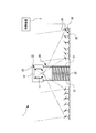
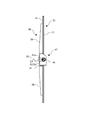
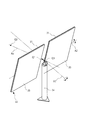
- the drive device 33 is rotatable about a first rotation axis 50 supported by a support base 34 so as to be rotatable about the first rotation axis A1 and a second rotation axis A2 as the center axis.
- a second rotating shaft 44 attached to the first rotating shaft 50, and a drive mechanism 49 that independently rotates each rotating shaft 50, 44 and changes the angle of the first rotating axis A1 with respect to the horizontal plane. ing.
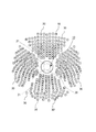
- the support frame 36 is disposed on the back surface of the back reinforcing plate 35. As shown in FIG. 4, the support frame 36 includes a plurality of support beam members 38 joined to the back surface of each back reinforcing plate 35, and a connecting member 42 that connects the plurality of support beam members 38 to each other. Yes.
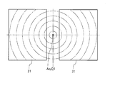
- the plurality of support beam members 38 are joined to the back reinforcing plate 35 so that the longitudinal direction thereof faces the radial direction from the optical axis Ao of the mirror structure 32.
- two support beam members 38 are provided for one back reinforcing plate 35.
- Each support beam member 38 has one end facing the optical axis Ao side and the other end facing the corner of the back reinforcing plate 35, that is, the corner of the mirror 31.
- the back reinforcing plate 35 is provided so as to form a V shape.
- two support beam members 38 are provided for one back reinforcing plate 35, that is, one mirror 31, from the viewpoint of strength, three or more support beam members 38 are provided. May be provided.
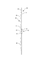
- the central axis of the shaft 44 that connects the connecting beams 41 passes through the principal point Q1 that is orthogonal to the optical axis Ao and that is the apex of the paraboloid of the mirror structure 32.
- the shaft 44 enters both arm portions 45a of the T-shaped tube 45 and is supported by a bearing (not shown) provided inside the T-shaped tube 45 so as to be rotatable around its own central axis. ing.
- the shaft 44 forms the second rotation axis described above, and the central axis of the shaft 44 forms the second rotation axis A2. Therefore, hereinafter, this shaft 44 is referred to as a second rotating shaft 44.
- the center of gravity position of the mirror structure 32 hardly moves. Absent. Moreover, the moment of trying to rotate the mirror structure 32 itself around the first rotation axis A1 or the second rotation axis A2 is hardly generated due to the weight of the mirror structure 32 itself.
- the driving force for rotating the mirror structure 32 can be reduced, the rigidity of the first rotating shaft 50 and the second rotating shaft 44, and the rotating shafts 50 and 44 can be reduced.
- the mirror structure 32 can be stably supported even when the rigidity of the support structure including the bearings that are rotatably supported is somewhat small.
- the sunlight reflected by the two mirrors 31 of the mirror structure 32 can be continuously irradiated accurately to the heat receiving portion 11 of the heat receiver 10.
- the optical axis Ao exists between the two mirrors 31 in the present embodiment, when the mirror structure 32 is rotated around the optical axis Ao, the reference of rotation between the plurality of mirrors is used.
- the rotation axis can be arranged, and the control of the direction of the optical axis Ao when irradiating light from the sun that moves in a diurnal motion to the fixed heat receiver can be simplified.
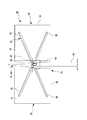
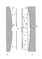
- the support beam facing surface 51c has a concave shape corresponding to the paraboloid of revolution which is the target shape of the reflecting surfaces of the two mirrors 31, like the back reinforcing plate facing surface 51a.
- the support beam facing surface 51 c is a surface that contacts the support beam member 38, the support beam facing surface 51 c is formed at a position recessed from the back reinforcing plate facing surface 51 a that contacts the back reinforcing plate 35.
- the support frame 36 to which the two back reinforcing plates 35 are joined is set on the lower mold 51.
- the second rotation shaft 44 and the T-shaped tube 45 of the support frame 36 are opposed to the rotation axis facing surface 51b of the lower mold 51, and the support beam member 38 of the support frame 36 is opposed to the support beam facing surface 51c.
- an adhesive agent is apply
- the adhesive may be applied quickly by, for example, a dispenser or a robot arm so that the previously applied adhesive is not dried and hardened in the process of being applied to the vertices of many convex portions.
- the correction state in the correction process is maintained, that is, the state in which the mirror 31, the back reinforcing plate 35, and the support beam member 38 are elastically deformed, the adhesive is cured, and the mirror 31 and the back surface reinforcement are maintained. Wait until the plate 35 is completely bonded.
- an elastic adhesive is used as an adhesive for adhering at least a part of the mirror 31 and the back reinforcing plate 35, the elasticity of the mirror 31 and the back reinforcing plate 35 is maintained even when the adhesive is cured. Is not lost.
- the upper mold 52 is removed from the lower mold 51, and the mirror structure 32 in which the two mirrors 31, the two back reinforcing plates 35 and the support frame 36 are integrated is taken out from the lower mold 51. .
- the mirror structure 32 is completed. Note that, in the manufacturing procedure of the mirror structure 32 described above, the steps S3 to S5 constitute a correction bonding step.
- the elastic deformation of the mirror 31, the back reinforcing plate 35 and the support beam member 38 is maintained by the curing of the adhesive, and the mirror 31, the back reinforcing plate 35 and the support frame 36 are integrated.
- One rigid body will be formed. In other words, in the present embodiment, the rigidity of the mirror structure 32 is ensured only when the mirror 31, the back reinforcing plate 35, and the support frame 36 are integrated.
- the mirror structure 32 can be easily transported and assembled in the field, and the driving force when the mirror structure 32 is directed in the target direction by the drive device 33 can be reduced.
- the present embodiment it is possible not only to save the trouble of individually processing the mirrors, but also to support the support frame 36, as compared with the case where a plurality of mirrors already forming a target three-dimensional curved surface are attached to the support frame or the like.
- the orientation and position adjustment of each mirror 31 with respect to can be made very easy, and the manufacturing process can be simplified.
- the target three-dimensional curved surface can be formed very accurately by the reflecting surfaces of the plurality of mirrors.
- the mirror 31 does not exist around the rotationally symmetric axis having the largest curvature on the target paraboloid, which is the target three-dimensional curved surface. You can avoid forcing.
- the mirror structure 32 having the two mirrors 31 is illustrated.
- the present invention is not limited to this. It is applicable also to what has the above mirror.
- the mirror structure 32 which has the rectangular plate-shaped mirror 32 is illustrated in the above embodiment, this invention is not limited to this, For example, other shapes, for example, a semicircular plate shape, are shown. It may be a mirror structure having a mirror.
Landscapes
- Engineering & Computer Science (AREA)
- Chemical & Material Sciences (AREA)
- Sustainable Development (AREA)
- Life Sciences & Earth Sciences (AREA)
- Combustion & Propulsion (AREA)
- Sustainable Energy (AREA)
- Mechanical Engineering (AREA)
- General Engineering & Computer Science (AREA)
- Physics & Mathematics (AREA)
- Thermal Sciences (AREA)
- Optical Elements Other Than Lenses (AREA)
- Mounting And Adjusting Of Optical Elements (AREA)
- Astronomy & Astrophysics (AREA)
- General Physics & Mathematics (AREA)
- Optics & Photonics (AREA)
Abstract
Priority Applications (3)
| Application Number | Priority Date | Filing Date | Title |
|---|---|---|---|
| US14/380,850 US9664416B2 (en) | 2012-03-28 | 2013-03-21 | Method for manufacturing mirror structure, mirror structure, light collection device having same, heat collection facility, and solar thermal power generation facility |
| AU2013242235A AU2013242235B2 (en) | 2012-03-28 | 2013-03-21 | Method for manufacturing mirror structure, mirror structure, light collection device having same, heat collection facility and solar thermal power generation facility |
| US15/260,434 US9999612B2 (en) | 2012-03-27 | 2016-09-09 | PPARs agonist activity enhancing drug |
Applications Claiming Priority (2)
| Application Number | Priority Date | Filing Date | Title |
|---|---|---|---|
| JP2012-074950 | 2012-03-28 | ||
| JP2012074950A JP2013204933A (ja) | 2012-03-28 | 2012-03-28 | 鏡構造体の製造方法、鏡構造体、これを備えている集光装置、集熱設備及び太陽熱発電設備 |
Related Child Applications (2)
| Application Number | Title | Priority Date | Filing Date |
|---|---|---|---|
| US14/388,012 A-371-Of-International US20150087846A1 (en) | 2012-03-27 | 2013-03-21 | PPARs AGONIST ACTIVITY ENHANCING DRUG |
| US14/814,013 Division US20160024041A1 (en) | 2012-03-27 | 2015-07-30 | PPARs AGONIST ACTIVITY ENHANCING DRUG |
Publications (1)
| Publication Number | Publication Date |
|---|---|
| WO2013146541A1 true WO2013146541A1 (fr) | 2013-10-03 |
Family
ID=49259797
Family Applications (1)
| Application Number | Title | Priority Date | Filing Date |
|---|---|---|---|
| PCT/JP2013/058107 Ceased WO2013146541A1 (fr) | 2012-03-27 | 2013-03-21 | Procédé de production d'une structure de miroir, structure de miroir, dispositif de collecte de lumière équipé de celle-ci, installation de collecte de chaleur et installation de générateur thermique et solaire |
Country Status (4)
| Country | Link |
|---|---|
| US (1) | US9664416B2 (fr) |
| JP (1) | JP2013204933A (fr) |
| AU (1) | AU2013242235B2 (fr) |
| WO (1) | WO2013146541A1 (fr) |
Cited By (1)
| Publication number | Priority date | Publication date | Assignee | Title |
|---|---|---|---|---|
| AU2015201631B2 (en) * | 2014-04-04 | 2020-03-19 | Commonwealth Scientific And Industrial Research Organisation | Method of designing a concentrated solar cavity receiver |
Families Citing this family (2)
| Publication number | Priority date | Publication date | Assignee | Title |
|---|---|---|---|---|
| JP2013181669A (ja) * | 2012-02-29 | 2013-09-12 | Mitsubishi Heavy Ind Ltd | 集光装置、その回転軸線の設定方法、集光装置を備えている集熱設備及び太陽熱発電設備 |
| WO2017184893A1 (fr) * | 2016-04-20 | 2017-10-26 | Norwich Technologies, Inc. | Collecteur à miroir pour miroir cylindro-parabolique solaire |
Citations (3)
| Publication number | Priority date | Publication date | Assignee | Title |
|---|---|---|---|---|
| JPS5835360A (ja) * | 1981-08-21 | 1983-03-02 | グラヴルベル | 複合鏡パネル |
| JPS63223601A (ja) * | 1987-03-12 | 1988-09-19 | Nippon Sheet Glass Co Ltd | 曲面鏡およびその製造方法 |
| JP2003124741A (ja) * | 2001-10-18 | 2003-04-25 | National Aerospace Laboratory Of Japan | 可変焦点距離電磁波集束装置 |
Family Cites Families (20)
| Publication number | Priority date | Publication date | Assignee | Title |
|---|---|---|---|---|
| JPS534947U (fr) | 1976-06-30 | 1978-01-17 | ||
| US4124277A (en) * | 1977-02-16 | 1978-11-07 | Martin Marietta Corporation | Parabolic mirror construction |
| US4276872A (en) * | 1978-11-13 | 1981-07-07 | Atlantic Richfield Company | Solar system employing ground level heliostats and solar collectors |
| JPS55121208U (fr) | 1979-02-17 | 1980-08-28 | ||
| GB2104238B (en) * | 1981-08-21 | 1985-01-30 | Glaverbel | Composite mirror panels |
| JPS6026347Y2 (ja) | 1981-10-06 | 1985-08-08 | プレス工業株式会社 | 太陽熱の追尾集光集熱を行う放物面鏡体支持骨格 |
| DE3225566C2 (de) | 1982-07-08 | 1987-03-19 | Flabeg GmbH, 8510 Fürth | Spiegel für Solar-Reflektoren |
| JPH07209508A (ja) * | 1994-01-18 | 1995-08-11 | Mitsubishi Heavy Ind Ltd | 宇宙集光器用反射鏡及びその製造方法 |
| AUPR403701A0 (en) * | 2001-03-28 | 2001-04-26 | Solar Systems Pty Ltd | A method of manufacturing mirrors for a dish reflector |
| JP3701264B2 (ja) | 2002-07-05 | 2005-09-28 | 三鷹光器株式会社 | 太陽光集光システム用のヘリオスタットおよびその制御方法 |
| WO2007034717A1 (fr) | 2005-09-26 | 2007-03-29 | Solar Hytech Co., Ltd. | Dispositif de support de miroirs reflechissants pour heliostat |
| JP2009139761A (ja) | 2007-12-07 | 2009-06-25 | Mitaka Koki Co Ltd | 太陽追尾集光装置 |
| JP2009267242A (ja) * | 2008-04-28 | 2009-11-12 | Nabtesco Corp | 太陽光発電装置 |
| JP2010019999A (ja) | 2008-07-09 | 2010-01-28 | Mitaka Koki Co Ltd | 十字型太陽追尾集光装置 |
| JP2010019468A (ja) | 2008-07-09 | 2010-01-28 | Mitaka Koki Co Ltd | 吊り型太陽追尾集光装置 |
| ES2425080T3 (es) * | 2008-08-21 | 2013-10-11 | Nabtesco Corporation | Dispositivo de transmisión de engranajes y dispositivo de generación de energía solar |
| JP2010101462A (ja) | 2008-10-27 | 2010-05-06 | Mitaka Koki Co Ltd | ヘリオスタットの駆動機構 |
| FR2951254B1 (fr) * | 2009-10-13 | 2013-10-04 | Claude Jacquot | Dispositif pour fixer un panneau solaire a une structure porteuse ayant des longerons |
| JP2013205643A (ja) | 2012-03-28 | 2013-10-07 | Mitsubishi Heavy Ind Ltd | パネル構造体、及びその製造方法 |
| JP2013204719A (ja) | 2012-03-28 | 2013-10-07 | Mitsubishi Heavy Ind Ltd | パネル構造体、及びその製造方法 |
-
2012
- 2012-03-28 JP JP2012074950A patent/JP2013204933A/ja active Pending
-
2013
- 2013-03-21 AU AU2013242235A patent/AU2013242235B2/en not_active Ceased
- 2013-03-21 US US14/380,850 patent/US9664416B2/en not_active Expired - Fee Related
- 2013-03-21 WO PCT/JP2013/058107 patent/WO2013146541A1/fr not_active Ceased
Patent Citations (3)
| Publication number | Priority date | Publication date | Assignee | Title |
|---|---|---|---|---|
| JPS5835360A (ja) * | 1981-08-21 | 1983-03-02 | グラヴルベル | 複合鏡パネル |
| JPS63223601A (ja) * | 1987-03-12 | 1988-09-19 | Nippon Sheet Glass Co Ltd | 曲面鏡およびその製造方法 |
| JP2003124741A (ja) * | 2001-10-18 | 2003-04-25 | National Aerospace Laboratory Of Japan | 可変焦点距離電磁波集束装置 |
Cited By (1)
| Publication number | Priority date | Publication date | Assignee | Title |
|---|---|---|---|---|
| AU2015201631B2 (en) * | 2014-04-04 | 2020-03-19 | Commonwealth Scientific And Industrial Research Organisation | Method of designing a concentrated solar cavity receiver |
Also Published As
| Publication number | Publication date |
|---|---|
| AU2013242235B2 (en) | 2015-10-01 |
| JP2013204933A (ja) | 2013-10-07 |
| US9664416B2 (en) | 2017-05-30 |
| US20150007566A1 (en) | 2015-01-08 |
| AU2013242235A1 (en) | 2014-09-18 |
Similar Documents
| Publication | Publication Date | Title |
|---|---|---|
| WO2013129177A1 (fr) | Dispositif de collecte de lumière, équipement de collecte de chaleur équipé de celui-ci, et équipement de génération d'énergie thermique solaire | |
| US20150287866A1 (en) | Solar receiver | |
| US20110000479A1 (en) | Solar tracker with thermal concentration | |
| JP2013202876A (ja) | レーザ溶着方法、レーザ溶着装置、レーザ溶着した樹脂材、及びレーザ溶着したカニューレ | |
| JP2013204933A (ja) | 鏡構造体の製造方法、鏡構造体、これを備えている集光装置、集熱設備及び太陽熱発電設備 | |
| WO2021062391A1 (fr) | Héliostat léger à focalisation active | |
| JP2002339859A (ja) | 電磁波集束装置 | |
| US20120275040A1 (en) | Precision parabolic mirror structures | |
| JP5785661B2 (ja) | ヘリオスタット用ミラーユニットの製造方法及び装置 | |
| CN102830715B (zh) | 一种光斑实时可调的定日镜调节方法 | |
| CN103715980B (zh) | 应用于空间太阳能电站的对称式两级平面反射聚集方法 | |
| CN103869457B (zh) | 一种功率密度可调的聚光式多用途卫星系统 | |
| JP2014119134A (ja) | 集光装置、及びこれを備えている集熱設備 | |
| JP2014102012A (ja) | 太陽熱発電用集光装置 | |
| US9188364B2 (en) | Parabolic solar energy collector apparatus | |
| CN106461270B (zh) | 用于集中太阳能发电的低成本的抛物柱面槽 | |
| WO2013129299A1 (fr) | Dispositif de collecte de lumière, procédé d'établissement de ligne axiale de rotation de ce dispositif, équipement de collecte de chaleur équipé de ce dispositif, et équipement de génération d'énergie thermique solaire | |
| AU2011349053A1 (en) | Heliostat construction | |
| CN108036527A (zh) | 一种新型碟式聚光镜结构 | |
| JP2014052102A (ja) | 集光装置、及びこれを備えている集熱設備 | |
| JP2018071928A (ja) | 海水淡水化装置における熱媒体加熱装置 | |
| WO2019232917A1 (fr) | Réflecteur à concentration de lumière incurvé et système de traitement associé, et ensemble de réflecteurs à concentration de lumière et procédé de fabrication associé | |
| WO2012108026A1 (fr) | Dispositif de chauffage solaire | |
| Li et al. | A new concept to form arc cylinders to parabolic troughs using optimal forces | |
| CN206191948U (zh) | 支撑镜的支撑结构、带有该支撑结构的太阳能收集器组件 |
Legal Events
| Date | Code | Title | Description |
|---|---|---|---|
| 121 | Ep: the epo has been informed by wipo that ep was designated in this application |
Ref document number: 13769055 Country of ref document: EP Kind code of ref document: A1 |
|
| WWE | Wipo information: entry into national phase |
Ref document number: 14380850 Country of ref document: US |
|
| ENP | Entry into the national phase |
Ref document number: 2013242235 Country of ref document: AU Date of ref document: 20130321 Kind code of ref document: A |
|
| NENP | Non-entry into the national phase |
Ref country code: DE |
|
| 122 | Ep: pct application non-entry in european phase |
Ref document number: 13769055 Country of ref document: EP Kind code of ref document: A1 |