WO2013154152A1 - 溝付き麺 - Google Patents
溝付き麺 Download PDFInfo
- Publication number
- WO2013154152A1 WO2013154152A1 PCT/JP2013/060917 JP2013060917W WO2013154152A1 WO 2013154152 A1 WO2013154152 A1 WO 2013154152A1 JP 2013060917 W JP2013060917 W JP 2013060917W WO 2013154152 A1 WO2013154152 A1 WO 2013154152A1
- Authority
- WO
- WIPO (PCT)
- Prior art keywords
- noodle
- noodle strings
- groove
- cross
- grooved
- Prior art date
- Legal status (The legal status is an assumption and is not a legal conclusion. Google has not performed a legal analysis and makes no representation as to the accuracy of the status listed.)
- Ceased
Links
Images





Classifications
-
- A—HUMAN NECESSITIES
- A23—FOODS OR FOODSTUFFS; TREATMENT THEREOF, NOT COVERED BY OTHER CLASSES
- A23L—FOODS, FOODSTUFFS OR NON-ALCOHOLIC BEVERAGES, NOT OTHERWISE PROVIDED FOR; PREPARATION OR TREATMENT THEREOF
- A23L7/00—Cereal-derived products; Malt products; Preparation or treatment thereof
- A23L7/10—Cereal-derived products
- A23L7/109—Types of pasta, e.g. macaroni or noodles
Definitions
- This invention relates to a grooved noodle, and more particularly to a grooved noodle in which two grooves are formed along the noodle string direction.
- noodles with cuts or grooves along the direction of the noodle strings have been proposed for the purpose of shortening the cooking time such as cooking.
- the noodles having four wedge-shaped grooves having a depth that does not reach the center of the noodle strings having a substantially circular cross section and the center of the noodle strings having a substantially circular cross section are reached.
- Noodles having a single wedge-shaped groove or rectangular groove having a depth are disclosed.
- Patent Document 2 discloses that a cross-sectional shape of a parallelogram noodle string is perpendicular to the diagonal line from two vertices located on both sides of one diagonal line of the parallelogram. Grooved noodles having a pair of V-shaped, U-shaped or rectangular grooves are proposed. It is described that with such grooved noodles, a good texture can be obtained in a short cooking time, and a good appearance can be obtained by closing the groove after cooking.
- the present invention has been made to solve such conventional problems, and provides a grooved noodle capable of shortening the cooking time and obtaining an excellent texture and appearance after cooking. Objective.
- the grooved noodles according to the present invention have a main shape in which the cross section of the noodle strings is a parallelogram or a rectangle, and the noodle strings are two in the noodle line direction at positions that are point-symmetric with respect to the center of the cross section of the noodle strings.
- each groove has a pair of first sides facing each other and extending from the opening surface of the groove toward the inside of the noodle strings, and tips of these first sides And a pair of second sides that are connected to each other to form the tip of the groove, and the distance from the tip of the groove to the opening surface of the groove in the cross section of the noodle strings It is larger than 1/2 of the width of the noodle strings in the forming direction.
- the ratio of the thickness of the noodle strings located between the two grooves and the opening width of the grooves is 1.0: 0.7 to 1.3.
- the angle of the tip of the groove is preferably 45 to 100 degrees.
- the bending angle between the first side and the second side is preferably 110 to 170 degrees in the cross section of the noodle strings.
- the area occupied by the two grooves is 15 to 65% of the area of the main outline of the noodle strings when there are no two grooves.
- the thickness of the portion having a construction area of about 80% from the center of the cross section of the noodle strings is 0.3 mm to 1.5 mm.
- the two grooves extend from the opposite corners of the main outline of the noodle strings toward the inside of the noodle strings, or from the opposite sides of the main outline of the noodle strings. It can form so that it may extend toward the inside.
- the pair of first sides of the groove may be inclined with respect to each other so that the distance between the front ends of the groove is narrow, or may extend in parallel with each other.
- each groove in the cross section of the noodle strings, has a pair of first sides facing each other and extending from the opening surface of the groove toward the inside of the noodle strings, and tips of the first sides. And a pair of second sides that are connected to each other to form the tip of the groove so that the cooking time is shortened and excellent texture and appearance after cooking Can be obtained.
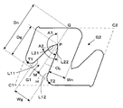
- FIG. 1 It is a fragmentary perspective view which shows the grooved noodle which concerns on Embodiment 1 of this invention. It is a cross-sectional view showing the grooved noodles according to the first embodiment. It is a figure which shows the cutting blade used at the time of manufacture of the grooved noodle which concerns on Embodiment 1.
- FIG. It is an enlarged view which shows the principal part of the cutting blade of FIG.
- It is a cross-sectional view showing a grooved noodle according to a modification of the first embodiment.
- FIG. 1 shows a grooved noodle 1 according to Embodiment 1 of the present invention.
- the noodle 1 is made of dry noodles stretched in the noodle line direction indicated by L in the figure.
- Two grooves G ⁇ b> 1 and G ⁇ b> 2 are formed along the noodle string direction L on the outer periphery of the noodle 1.
- the noodle strings have a substantially parallelogram-shaped main outline in the cross section. That is, when it is assumed that there are no two grooves G1 and G2, the noodle 1 has a substantially parallelogram-shaped cross-sectional shape. Grooves G1 and G2 extend from the opposite corners C1 and C2 of the parallelogram, which is the main outline of the noodle strings, toward the inside of the noodle strings, and are arranged at positions that are point-symmetric with respect to the center of the parallelogram. Has been.
- Grooves G1 and G2 have the same cross-sectional shape in the cross section of the noodle strings, and a pair of linear first sides L11 extending from the opening surface H of the groove toward the inside of the noodle strings, respectively.
- L12 and linear second sides L21 and L22 connected to the tips of the first sides L11 and L12, respectively.
- the first sides L11 and L12 extend so as to face each other while being inclined so that the gap on the tip portion P side of the groove is narrowed, and the second side L21 is formed at the tip of the first side L11.
- the second side L22 is connected to the tip of one side L12.
- the second sides L21 and L22 extend in a bent direction so as to approach each other from the tips of the first sides L11 and L12, and a tip portion P of the groove is formed by the intersection of the second sides L21 and L22. ing. That is, unlike the V-shaped, U-shaped, or rectangular grooves as shown in Patent Documents 1 and 2 described above, the grooves G1 and G2 have a polygonal cross-sectional shape whose inclination angle changes in two steps. .
- the opening surface H of the grooves G1 and G2 is defined by a plane that is in contact with the noodle strings on both sides of the groove so as to cover the opening of the grooves and is located between the contacts T1 and T2 with the noodle strings. To do. Further, in the cross section of the noodle strings, when the intersection between the center line CL of each groove and the opening surface H is M, and the distance Dg from the intersection M to the groove tip P is the groove depth, the groove G1 The depths of G2 and G2 are set to be larger than 1 ⁇ 2 of the width of the noodle strings in the groove forming direction.
- the width of the noodle strings in the groove forming direction is expressed as follows from the intersection M between the groove center line CL and the opening surface H, where Q is the point where the groove center line CL is extended and intersects with the outline of the noodle strings. It is represented by a distance Dn to the point Q. That is, the grooves G1 and G2 are formed to a position deeper than the midpoint of the line segment MQ connecting the point M and the point Q in the groove forming direction.
- each of the grooves G1 and G2 includes the first side L11 and L12 and the second side that bends from the tips of the sides L11 and L12 and reaches the tip part P in the cross section of the noodle strings. Since it has L21 and L22 and has a depth larger than 1 ⁇ 2 of the width of the noodle strings in the groove forming direction, it has a large surface area, and moisture and heat efficiently and quickly inside the noodle strings. To be absorbed.
- the cross-sectional shapes of the grooves G1 and G2 are the same as those of the grooves G1 and G2 because they have a polygonal shape whose inclination angle changes in two steps by the first side L11 and L12 and the second side L21 and L22 Compared to a simple V-shaped groove having an opening width and depth, the clogging is not accelerated, and water and heat sufficiently penetrated into the inside of the noodle strings by the hot water that has entered the grooves G1 and G2. It will go up quickly with a kite.
- the maximum distance between the first sides L11 and L12 measured in the direction perpendicular to the groove center line CL, that is, the distance between the first sides L11 and L12 on the opening side of the groove is the groove.
- the ratio of the thickness Wn of the noodle strings located between the two grooves G1 and G2 to the opening width Wg of the groove is 1.0: 0.7 to 1.3. It is desirable to set. By doing in this way, sufficient blockage of the grooves G1 and G2 after cooking and shortening of the cooking time can be made compatible.
- the bending angle between the first side L11 and the second side L21 and the bending angle A1 between the first side L12 and the second side L22 are set within a range of 110 to 170 degrees.
- the angle A2 at the tip P of the groove formed between the second sides L21 and L22 is preferably set within a range of 45 to 100 degrees.
- the cross-sectional area inside the groove closed by the opening surface H of the groove is the area occupied by the groove
- the sum of the areas occupied by the two grooves G1 and G2 is It is preferably set to 15 to 65% of the area of the main outline of the noodle strings when there is no G2.
- the length of each side of the parallelogram which is the main outline of the noodle strings, is set to 1 to 6 mm, and a part that greatly affects the strength of the noodles in terms of production, for example, the noodle strings
- the thickness of the noodle strings in the portion having a construction area of about 80% from the center of the parallelogram as the main outer shape is set to 0.3 mm to 1.5 mm.
- the grooved noodle 1 of Embodiment 1 can be manufactured using, for example, a cutting blade as shown in FIG.
- a plurality of disc-shaped cutting blades 13 and 14 are mounted on the pair of rotating shafts 11 and 12, respectively, and the pair of rotating shafts 11 and 12 are parallel to each other so that the tips of the cutting blades 13 and 14 are close to each other.
- cutting surfaces F ⁇ b> 1 and F ⁇ b> 2 having different inclination angles are formed at the tips of the cutting blades 13 and 14.
- the noodle dough is passed between the tips of the cutting blades 13 and 14 while the cutting blades 13 and 14 are rotated in opposite directions by the rotating shafts 11 and 12.
- a grooved noodle 1 having a simple cross-sectional shape is manufactured.
- the first sides L11 and L12 and the second sides L21 and L22 of the grooves G1 and G2 whose inclination angles change in two steps are formed by the cut surfaces F1 and F2 of the cutting blades 13 and 14.
- the grooved noodles 1 can also be produced by extruding the dough of noodles using a die having a die hole corresponding to the cross-sectional shape of the grooved noodles 1 instead of the cutting blades.
- the first sides L11 and L12 of the grooves G1 and G2 extend opposite to each other while being inclined with respect to each other so that the gap on the tip end portion P side of the groove is narrowed.
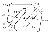
- the present invention is not limited to this, and the first sides L11 and L12 may extend in parallel to each other like the grooved noodle 2 shown in FIG.
- the second sides L21 and L22 are bent and connected to the tips of the first sides L11 and L12, respectively, and the tip portion P of the groove is formed by the intersection of the second sides L21 and L22. It is formed. Even with such grooved noodles 2, like the grooved noodles 1 described above, it is possible to shorten the cooking time and to obtain an excellent texture and appearance after cooking.
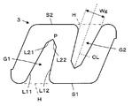
- Embodiment 2 In the grooved noodle 1 according to Embodiment 1 described above, the grooves G1 and G2 extend toward the inside of the noodle strings from the mutually opposite corners C1 and C2 of the parallelogram that is the main outline of the noodle strings. However, like the grooved noodle 3 of the second embodiment shown in FIG. 6, a groove G1 extending from the parallel sides of the parallelogram, which is the main outline of the noodle strings, to the inside of the noodle strings from opposite sides S1 and S2 And G2 can also be formed.
- the grooves G1 and G2 are arranged at positions that are point-symmetric with respect to the center of the parallelogram, and are respectively defined by the first side L11 and L12 and the second side L21 and L22. It has a polygonal shape in which the inclination angle changes in two steps, and has a depth larger than 1 ⁇ 2 of the width of the noodle strings in the groove forming direction. Even with such grooved noodles 3, like the grooved noodles 1, it is possible to shorten the cooking time and obtain an excellent texture and appearance after cooking.
- the first sides L11 and L12 of the grooves G1 and G2 extend opposite to each other while being inclined with respect to each other so that the gap on the front end portion P side of the groove is narrowed.
- the present invention is not limited to this, and the first sides L11 and L12 may extend in parallel to each other like the grooved noodle 4 shown in FIG.
- the second sides L21 and L22 are bent and connected to the tips of the first sides L11 and L12, respectively, and the tip of the groove is formed by the intersection of the second sides L21 and L22. P is formed. That is, the grooves G1 and G2 have a polygonal shape whose inclination angle changes in two steps. Even with such grooved noodles 4, like the grooved noodles 3, it is possible to shorten the cooking time and to obtain an excellent texture and appearance after cooking.
- the noodle strings have a main shape of a substantially parallelogram.
- the noodle strings may have a rectangular main outer shape.
- the grooves G1 and G2 extend from the mutually opposing sides S1 and S2 of the rectangle that is the main outline of the noodle strings toward the inside of the noodle strings.
- Grooves G1 and G2 have polygonal shapes in which the inclination angle changes in two steps by first side L11 and L12 and second side L21 and L22, respectively, and are 1 / of the width of the noodle strings in the groove forming direction. It has a depth greater than 2. Even with such grooved noodles 3, like the grooved noodles 1, it is possible to shorten the cooking time and obtain an excellent texture and appearance after cooking.
- the first sides L11 and L12 of the grooves G1 and G2 extend opposite to each other while being inclined with respect to each other so that the gap on the tip end portion P side of the groove is narrowed.
- the present invention is not limited to this, and the first sides L11 and L12 may extend in parallel to each other like the grooved noodle 6 shown in FIG.
- the second sides L21 and L22 are bent and connected to the tips of the first sides L11 and L12, respectively, and the tip of the groove is formed by the intersection of the second sides L21 and L22. P is formed. That is, the grooves G1 and G2 have a polygonal shape whose inclination angle changes in two steps. Even with such grooved noodles 6, like the grooved noodles 5, it is possible to shorten the cooking time and obtain an excellent texture and appearance after cooking.
- the grooves G1 and G2 are formed from the opposite sides S1 and S2 of the rectangle which is the main outline of the noodle strings. Although extending toward the inside, similarly, grooves G1 and G2 extending toward the inside of the noodle strings from the opposite corners of the rectangle, which is the main outline of the noodle strings, can also be formed.
- this invention can be applied to various noodles such as pasta and the like in addition to udon, soba, cold wheat, and Chinese noodles.
- the present invention can be applied to various forms of noodles such as raw noodles, rice noodles, steamed noodles, and instant noodles.
- Comparative Example 1 Grooved noodles having the same cross-sectional shape as in FIG. 2 as in Production Examples 1 to 5 except that the shape of the groove was V-shaped (angle at the tip of 15 degrees). The obtained noodles were dried under mild hot and humid conditions until the water content became 13%. All the grooved noodles had a depth greater than 1 ⁇ 2 of the width of the noodle strings in the groove forming direction.
- Appearance evaluation criteria 4 Equivalent to noodles without grooves and smooth appearance 3: Almost same as noodles without grooves and almost smooth appearance 2: Slightly bumpy and slightly lacking in smoothness 1: Evaluation criteria for the texture that is bumpy and not smooth enough 4: Equivalent to noodles without grooves, good texture 3: Slightly good texture, almost equivalent to noodles without grooves 2: Slightly softer and slightly worse texture compared to non-grooved noodles 1: Softer and poorer texture than non-grooved noodles
Landscapes
- Health & Medical Sciences (AREA)
- Nutrition Science (AREA)
- Life Sciences & Earth Sciences (AREA)
- Chemical & Material Sciences (AREA)
- Engineering & Computer Science (AREA)
- Food Science & Technology (AREA)
- Polymers & Plastics (AREA)
- Noodles (AREA)
Abstract
Description
また、溝の横断面形状をU字形あるいは矩形とした場合には、茹で上がった際に溝が十分に閉塞しなかったり、溝の開口部が閉じているにも関わらず、溝の奥部が閉塞せずに麺の内部に空隙を生じて、食感を損なうおそれがあった。
また、麺線の横断面において、溝の先端部の角度は、45~100度であることが好ましい。この場合、さらに、麺線の横断面において、第1の辺と第2の辺との間の屈曲角は、110~170度であることが好ましい。
好ましくは、麺線の横断面において、2本の溝が占める面積は、2本の溝がないものとしたときの麺線の主外形の面積の15~65%である。
また、麺線の横断面の中心から構成面積約80%の部分における肉厚は、0.3mm~1.5mmであることが好ましい。
また、麺線の横断面において、溝の一対の第1の辺は、溝の先端部側の間隔が狭くなるように互いに傾斜していてもよく、あるいは、互いに平行に延びていてもよい。
実施の形態1
図1に、この発明の実施の形態1に係る溝付き麺1を示す。麺1は、図中Lで示される麺線方向に延伸した乾麺からなっている。麺1の外周部には、麺線方向Lに沿って2本の溝G1およびG2が形成されている。
すなわち、溝G1およびG2は、上述した特許文献1および2に示されるようなV字形、U字形または矩形の溝と異なり、傾斜角度が2段に変化する多角形状の断面形状を有している。
このため、加熱調理時間が短くても、加熱調理後に優れた食感が得られると共に、溝なしの麺と同様の外観および舌触りが得られることとなる。
また、麺線の断面形状において、麺線の主外形である平行四辺形の各辺の長さは、1~6mmに設定され、製造面での麺強度を大きく左右する部分、例えば麺線の主外形である平行四辺形の中心から構成面積約80%の部分における麺線の肉厚は、0.3mm~1.5mmに設定されることが好ましい。
このような構造を有する溝付き麺1により、加熱調理時間の短縮と加熱調理後における優れた食感および外観を得ることが可能となる。
なお、切刃の代わりに、溝付き麺1の断面形状に対応するダイ穴を有するダイスを用いて麺の生地を押出成形することによっても、溝付き麺1を製造することができる。
このような溝付き麺2によっても、上述した溝付き麺1と同様に、加熱調理時間の短縮と加熱調理後における優れた食感および外観を得ることが可能となる。
上記の実施の形態1に係る溝付き麺1では、溝G1およびG2が、麺線の主外形である平行四辺形の互いに対向する角部C1およびC2から麺線の内部に向かって延びていたが、図6に示される実施の形態2の溝付き麺3のように、麺線の主外形である平行四辺形の互いに対向する辺部S1およびS2から麺線の内部に向かって延びる溝G1およびG2を形成することもできる。
この場合も、麺線の横断面において、溝G1およびG2は、平行四辺形の中心に関して点対称となる位置に配置され、それぞれ、第1の辺L11およびL12と第2の辺L21およびL22により傾斜角度が2段に変化する多角形状を有し、溝の形成方向における麺線の幅の1/2よりも大きな深さを有している。
このような溝付き麺3によっても、溝付き麺1と同様に、加熱調理時間の短縮と加熱調理後における優れた食感および外観を得ることが可能となる。
このような溝付き麺4によっても、溝付き麺3と同様に、加熱調理時間の短縮と加熱調理後における優れた食感および外観を得ることができる。
上記の実施の形態1および2に係る溝付き麺1~4では、麺線がほぼ平行四辺形の主外形を有していたが、例えば図8に示される実施の形態3の溝付き麺5のように、麺線が矩形の主外形を有していてもよい。
麺線の横断面において、溝G1およびG2が、麺線の主外形である矩形の互いに対向する辺部S1およびS2から麺線の内部に向かって延びている。溝G1およびG2は、それぞれ、第1の辺L11およびL12と第2の辺L21およびL22により傾斜角度が2段に変化する多角形状を有し、溝の形成方向における麺線の幅の1/2よりも大きな深さを有している。
このような溝付き麺3によっても、溝付き麺1と同様に、加熱調理時間の短縮と加熱調理後における優れた食感および外観を得ることが可能となる。
このような溝付き麺6によっても、溝付き麺5と同様に、加熱調理時間の短縮と加熱調理後における優れた食感および外観を得ることができる。
また、この発明は、乾麺の他、生麺、茹麺、蒸麺、即席麺等、各種の形態の麺に適用することが可能である。
準強力小麦粉100質量部に対し、10%食塩水36質量部を加え、ピンミキサーにて10分間ミキシングを行い、得られた麺生地を、常法に従い、ロールにて最終麺帯厚みが2.4mmになるように圧延比30~50%で圧延した。この麺帯から、切刃を用いて、図2と同様の断面形状を有し、ただし溝の第1の辺L11と第2の辺L21の成す角度A1(L12とL22の成す角度も同じ)、辺L21とL22の成す角度A2、及び溝と溝の間に位置する麺線部分の肉厚Wnと溝の開口幅Wgとの比を表1のようにした各種溝付き麺を製造例1~5として製造した。得られた麺を水分含量13%になるまで穏やかな温湿条件で乾燥した。なお、いずれの溝付き麺も、溝の深さは溝の形成方向における麺線の幅の1/2より大きな深さを有していた。
製造例1~5と同じく図2と同様の断面形状を有し、ただし溝の形状をV字形(先端部の角度15度)にして、溝付き麺を製造した。得られた麺を水分含量13%になるまで穏やかな温湿条件で乾燥した。なお、いずれの溝付き麺も、溝の深さは溝の形成方向における麺線の幅の1/2より大きな深さを有していた。
4:溝無しの麺と同等であり、滑らかな外観
3:溝無しの麺とほぼ同等であり、ほぼ滑らかな外観
2:わずかにでこぼこしており、滑らかさにやや足りない外観
1:でこぼこしており、滑らかさに足りない外観
食感の評価基準
4:溝無しの麺と同等であり、良好な食感
3:溝無しの麺とほぼ同等であり、やや良好な食感
2:溝無しの麺に比べやや柔らかく、やや不良な食感
1:溝無しの麺に比べ柔らかく、不良な食感

Claims (10)
- 麺線の横断面が平行四辺形または矩形の主外形を有し、
前記麺線の横断面の中心に関して点対称となる位置に、前記麺線方向に沿った2本の溝を有し、
前記麺線の横断面において、それぞれの前記溝は、互いに対向し且つ前記溝の開口面から前記麺線の内部に向かって延びる一対の第1の辺と、これら第1の辺の先端で互いに接近する方向に屈曲し且つ互いに接続されて前記溝の先端部を形成する一対の第2の辺とを有し、
前記溝の先端部から開口面までの距離が前記麺線の横断面の前記溝の形成方向における前記麺線の幅の1/2よりも大きいことを特徴とする溝付き麺。 - 前記麺線の横断面において、前記2本の溝の間に位置する前記麺線の部分の肉厚と前記溝の開口幅との比が、1.0:0.7~1.3である請求項1に記載の溝付き麺。
- 前記麺線の横断面において、前記溝の先端部の角度は、45~100度である請求項1または2に記載の溝付き麺。
- 前記麺線の横断面において、前記第1の辺と前記第2の辺との間の屈曲角は、110~170度である請求項3に記載の溝付き麺。
- 前記麺線の横断面において、前記2本の溝が占める面積は、前記2本の溝がないものとしたときの前記麺線の主外形の面積の15~65%である請求項1~4のいずれか一項に記載の溝付き麺。
- 前記麺線の横断面の中心から構成面積約80%の部分における肉厚が0.3mm~1.5mmである請求項1~5のいずれか一項に記載の溝付き麺。
- 前記麺線の横断面において、前記2本の溝は、前記麺線の主外形の互いに対向する角部から前記麺線の内部に向かって延びている請求項1~6のいずれか一項に記載の溝付き麺。
- 前記麺線の横断面において、前記2本の溝は、前記麺線の主外形の互いに対向する辺部から前記麺線の内部に向かって延びている請求項1~6のいずれか一項に記載の溝付き麺。
- 前記麺線の横断面において、前記溝の前記一対の第1の辺は、前記溝の先端部側の間隔が狭くなるように互いに傾斜している請求項1~8のいずれか一項に記載の溝付き麺。
- 前記麺線の横断面において、前記溝の前記一対の第1の辺は、互いに平行に延びている請求項1~8のいずれか一項に記載の溝付き麺。
Priority Applications (4)
| Application Number | Priority Date | Filing Date | Title |
|---|---|---|---|
| JP2014510196A JP6140688B2 (ja) | 2012-04-11 | 2013-04-11 | 溝付き麺 |
| CN201380018830.0A CN104302189A (zh) | 2012-04-11 | 2013-04-11 | 带沟面条 |
| EP13775386.9A EP2837291A4 (en) | 2012-04-11 | 2013-04-11 | STUFFED NOODLE |
| US14/512,182 US20150030745A1 (en) | 2012-04-11 | 2014-10-10 | Grooved noodle |
Applications Claiming Priority (2)
| Application Number | Priority Date | Filing Date | Title |
|---|---|---|---|
| JP2012-089930 | 2012-04-11 | ||
| JP2012089930 | 2012-04-11 |
Related Child Applications (1)
| Application Number | Title | Priority Date | Filing Date |
|---|---|---|---|
| US14/512,182 Continuation US20150030745A1 (en) | 2012-04-11 | 2014-10-10 | Grooved noodle |
Publications (1)
| Publication Number | Publication Date |
|---|---|
| WO2013154152A1 true WO2013154152A1 (ja) | 2013-10-17 |
Family
ID=49327710
Family Applications (1)
| Application Number | Title | Priority Date | Filing Date |
|---|---|---|---|
| PCT/JP2013/060917 Ceased WO2013154152A1 (ja) | 2012-04-11 | 2013-04-11 | 溝付き麺 |
Country Status (5)
| Country | Link |
|---|---|
| US (1) | US20150030745A1 (ja) |
| EP (1) | EP2837291A4 (ja) |
| JP (1) | JP6140688B2 (ja) |
| CN (1) | CN104302189A (ja) |
| WO (1) | WO2013154152A1 (ja) |
Families Citing this family (8)
| Publication number | Priority date | Publication date | Assignee | Title |
|---|---|---|---|---|
| JP3024004B2 (ja) | 1991-05-13 | 2000-03-21 | 旭電化工業株式会社 | 水性エポキシ樹脂硬化性組成物 |
| JP3024006B2 (ja) | 1991-05-28 | 2000-03-21 | 旭電化工業株式会社 | 水性エポキシ樹脂硬化性組成物 |
| US9004899B2 (en) * | 2012-02-07 | 2015-04-14 | Sanyo Foods Co., Ltd. | Noodles and apparatus for processing the same |
| USD707419S1 (en) * | 2013-02-07 | 2014-06-24 | Nisshin Foods Inc. | Macaroni |
| EP3351115B1 (en) * | 2015-09-14 | 2021-10-27 | Nisshin Foods Inc. | Grooved noodles |
| USD817591S1 (en) * | 2015-12-01 | 2018-05-15 | Nisshin Foods Inc. | Dried noodle |
| USD914804S1 (en) * | 2019-11-07 | 2021-03-30 | J.R. Simplot Company | Potato piece |
| CN114073258A (zh) * | 2020-08-10 | 2022-02-22 | 财团法人食品工业发展研究所 | 用于形成特殊形状面条的模具 |
Citations (6)
| Publication number | Priority date | Publication date | Assignee | Title |
|---|---|---|---|---|
| JPS606172A (ja) | 1983-06-22 | 1985-01-12 | Nisshin Flour Milling Co Ltd | 溝付き押出成形麺 |
| JPH02200155A (ja) * | 1989-01-27 | 1990-08-08 | Nisshin Flour Milling Co Ltd | 溝付き押出麺類 |
| JPH03280849A (ja) * | 1990-03-30 | 1991-12-11 | Nisshin Flour Milling Co Ltd | 溝付き麺類 |
| JPH08242795A (ja) * | 1995-03-07 | 1996-09-24 | Yukiko Niitsu | 即席麺の製造方法 |
| WO2008090802A1 (ja) * | 2007-01-25 | 2008-07-31 | Nisshin Foods Inc. | 溝付き麺類およびその製造方法 |
| JP2011004701A (ja) * | 2009-06-29 | 2011-01-13 | Nisshin Foods Kk | 溝付き麺 |
Family Cites Families (6)
| Publication number | Priority date | Publication date | Assignee | Title |
|---|---|---|---|---|
| JP3586000B2 (ja) * | 1995-06-28 | 2004-11-10 | 株式会社冨士製作所 | 麺の製造装置 |
| FR2738461B1 (fr) * | 1995-09-08 | 1997-11-14 | Rivoire Et Carret Lustucru | Pate alimentaire du genre spaghetti a deux lobes |
| JP3484280B2 (ja) * | 1995-12-08 | 2004-01-06 | マ・マーマカロニ株式会社 | 溝付き押出成形麺 |
| JP2001017104A (ja) * | 1999-07-09 | 2001-01-23 | Showa Sangyo Co Ltd | 早茹でスパゲッティ |
| JP2005206297A (ja) * | 2004-01-21 | 2005-08-04 | Three M Innovative Properties Co | 凹形断面ストリップの取付装置 |
| JP2007049920A (ja) * | 2005-08-17 | 2007-03-01 | Nippon Flour Mills Co Ltd | 複数の孔を有する押出成形麺 |
-
2013
- 2013-04-11 WO PCT/JP2013/060917 patent/WO2013154152A1/ja not_active Ceased
- 2013-04-11 EP EP13775386.9A patent/EP2837291A4/en not_active Withdrawn
- 2013-04-11 JP JP2014510196A patent/JP6140688B2/ja active Active
- 2013-04-11 CN CN201380018830.0A patent/CN104302189A/zh active Pending
-
2014
- 2014-10-10 US US14/512,182 patent/US20150030745A1/en not_active Abandoned
Patent Citations (7)
| Publication number | Priority date | Publication date | Assignee | Title |
|---|---|---|---|---|
| JPS606172A (ja) | 1983-06-22 | 1985-01-12 | Nisshin Flour Milling Co Ltd | 溝付き押出成形麺 |
| JPH02200155A (ja) * | 1989-01-27 | 1990-08-08 | Nisshin Flour Milling Co Ltd | 溝付き押出麺類 |
| JPH03280849A (ja) * | 1990-03-30 | 1991-12-11 | Nisshin Flour Milling Co Ltd | 溝付き麺類 |
| JP2807536B2 (ja) | 1990-03-30 | 1998-10-08 | 日清製粉株式会社 | 溝付き麺類 |
| JPH08242795A (ja) * | 1995-03-07 | 1996-09-24 | Yukiko Niitsu | 即席麺の製造方法 |
| WO2008090802A1 (ja) * | 2007-01-25 | 2008-07-31 | Nisshin Foods Inc. | 溝付き麺類およびその製造方法 |
| JP2011004701A (ja) * | 2009-06-29 | 2011-01-13 | Nisshin Foods Kk | 溝付き麺 |
Non-Patent Citations (1)
| Title |
|---|
| See also references of EP2837291A4 |
Also Published As
| Publication number | Publication date |
|---|---|
| US20150030745A1 (en) | 2015-01-29 |
| CN104302189A (zh) | 2015-01-21 |
| JPWO2013154152A1 (ja) | 2015-12-17 |
| EP2837291A4 (en) | 2015-11-25 |
| EP2837291A1 (en) | 2015-02-18 |
| JP6140688B2 (ja) | 2017-05-31 |
Similar Documents
| Publication | Publication Date | Title |
|---|---|---|
| JP6140688B2 (ja) | 溝付き麺 | |
| JP5726493B2 (ja) | 溝付き麺 | |
| US20100080882A1 (en) | Grooved noodles and process for producing the same | |
| JP5102252B2 (ja) | 溝付き麺 | |
| JP2024525324A (ja) | 溝を備えたブロンズ製ダイプレートインサートから押し出すことでパスタを製造する方法 | |
| JP4970198B2 (ja) | 溝付き麺類 | |
| JP2001017104A (ja) | 早茹でスパゲッティ | |
| WO2018025838A1 (ja) | 調理済み溝付き麺 | |
| JP2807536B2 (ja) | 溝付き麺類 | |
| JP6737792B2 (ja) | 溝付き麺 | |
| WO2023145798A1 (ja) | 溝付き麺 | |
| JP5746673B2 (ja) | 溝付き麺類 | |
| JP5345229B2 (ja) | 溝付き麺類 | |
| WO2014064948A1 (ja) | マカロニ | |
| JPH09154514A (ja) | 溝付き押出成形麺 | |
| CN309561931S (zh) | 料理机(ymj-d650) | |
| JP2005110600A (ja) | 麺類用の回転式裁断装置及びその装置により切出された麺線 | |
| JP3203938U (ja) | 製麺用切刃ロール | |
| HK1248474B (en) | Grooved noodles |
Legal Events
| Date | Code | Title | Description |
|---|---|---|---|
| 121 | Ep: the epo has been informed by wipo that ep was designated in this application |
Ref document number: 13775386 Country of ref document: EP Kind code of ref document: A1 |
|
| ENP | Entry into the national phase |
Ref document number: 2014510196 Country of ref document: JP Kind code of ref document: A |
|
| REEP | Request for entry into the european phase |
Ref document number: 2013775386 Country of ref document: EP |
|
| WWE | Wipo information: entry into national phase |
Ref document number: 2013775386 Country of ref document: EP |
|
| NENP | Non-entry into the national phase |
Ref country code: DE |