WO2013157274A1 - 水素生成装置及び燃料電池システム - Google Patents
水素生成装置及び燃料電池システム Download PDFInfo
- Publication number
- WO2013157274A1 WO2013157274A1 PCT/JP2013/002648 JP2013002648W WO2013157274A1 WO 2013157274 A1 WO2013157274 A1 WO 2013157274A1 JP 2013002648 W JP2013002648 W JP 2013002648W WO 2013157274 A1 WO2013157274 A1 WO 2013157274A1
- Authority
- WO
- WIPO (PCT)
- Prior art keywords
- channel
- flow path
- hydrogen
- fuel cell
- recycle
- Prior art date
- Legal status (The legal status is an assumption and is not a legal conclusion. Google has not performed a legal analysis and makes no representation as to the accuracy of the status listed.)
- Ceased
Links
Images


Classifications
-
- H—ELECTRICITY
- H01—ELECTRIC ELEMENTS
- H01M—PROCESSES OR MEANS, e.g. BATTERIES, FOR THE DIRECT CONVERSION OF CHEMICAL ENERGY INTO ELECTRICAL ENERGY
- H01M8/00—Fuel cells; Manufacture thereof
- H01M8/06—Combination of fuel cells with means for production of reactants or for treatment of residues
- H01M8/0662—Treatment of gaseous reactants or gaseous residues, e.g. cleaning
- H01M8/0675—Removal of sulfur
-
- C—CHEMISTRY; METALLURGY
- C01—INORGANIC CHEMISTRY
- C01B—NON-METALLIC ELEMENTS; COMPOUNDS THEREOF; METALLOIDS OR COMPOUNDS THEREOF NOT COVERED BY SUBCLASS C01C
- C01B3/00—Hydrogen; Gaseous mixtures containing hydrogen; Separation of hydrogen from mixtures containing it; Purification of hydrogen; Reversible storage of hydrogen
- C01B3/02—Production of hydrogen; Production of gaseous mixtures containing hydrogen
- C01B3/32—Production of hydrogen; Production of gaseous mixtures containing hydrogen by reaction of gaseous or liquid organic compounds with gasifying agents, e.g. water, carbon dioxide or air
- C01B3/34—Production of hydrogen; Production of gaseous mixtures containing hydrogen by reaction of gaseous or liquid organic compounds with gasifying agents, e.g. water, carbon dioxide or air by reaction of hydrocarbons with gasifying agents
- C01B3/38—Production of hydrogen; Production of gaseous mixtures containing hydrogen by reaction of gaseous or liquid organic compounds with gasifying agents, e.g. water, carbon dioxide or air by reaction of hydrocarbons with gasifying agents using catalysts
-
- H—ELECTRICITY
- H01—ELECTRIC ELEMENTS
- H01M—PROCESSES OR MEANS, e.g. BATTERIES, FOR THE DIRECT CONVERSION OF CHEMICAL ENERGY INTO ELECTRICAL ENERGY
- H01M8/00—Fuel cells; Manufacture thereof
- H01M8/04—Auxiliary arrangements, e.g. for control of pressure or for circulation of fluids
- H01M8/04082—Arrangements for control of reactant parameters, e.g. pressure or concentration
- H01M8/04089—Arrangements for control of reactant parameters, e.g. pressure or concentration of gaseous reactants
- H01M8/04119—Arrangements for control of reactant parameters, e.g. pressure or concentration of gaseous reactants with simultaneous supply or evacuation of electrolyte; Humidifying or dehumidifying
- H01M8/04156—Arrangements for control of reactant parameters, e.g. pressure or concentration of gaseous reactants with simultaneous supply or evacuation of electrolyte; Humidifying or dehumidifying with product water removal
-
- H—ELECTRICITY
- H01—ELECTRIC ELEMENTS
- H01M—PROCESSES OR MEANS, e.g. BATTERIES, FOR THE DIRECT CONVERSION OF CHEMICAL ENERGY INTO ELECTRICAL ENERGY
- H01M8/00—Fuel cells; Manufacture thereof
- H01M8/06—Combination of fuel cells with means for production of reactants or for treatment of residues
- H01M8/0606—Combination of fuel cells with means for production of reactants or for treatment of residues with means for production of gaseous reactants
- H01M8/0612—Combination of fuel cells with means for production of reactants or for treatment of residues with means for production of gaseous reactants from carbon-containing material
- H01M8/0618—Reforming processes, e.g. autothermal, partial oxidation or steam reforming
-
- B—PERFORMING OPERATIONS; TRANSPORTING
- B01—PHYSICAL OR CHEMICAL PROCESSES OR APPARATUS IN GENERAL
- B01J—CHEMICAL OR PHYSICAL PROCESSES, e.g. CATALYSIS OR COLLOID CHEMISTRY; THEIR RELEVANT APPARATUS
- B01J2219/00—Chemical, physical or physico-chemical processes in general; Their relevant apparatus
- B01J2219/24—Stationary reactors without moving elements inside
-
- C—CHEMISTRY; METALLURGY
- C01—INORGANIC CHEMISTRY
- C01B—NON-METALLIC ELEMENTS; COMPOUNDS THEREOF; METALLOIDS OR COMPOUNDS THEREOF NOT COVERED BY SUBCLASS C01C
- C01B2203/00—Integrated processes for the production of hydrogen or synthesis gas
- C01B2203/02—Processes for making hydrogen or synthesis gas
- C01B2203/0205—Processes for making hydrogen or synthesis gas containing a reforming step
- C01B2203/0227—Processes for making hydrogen or synthesis gas containing a reforming step containing a catalytic reforming step
- C01B2203/0244—Processes for making hydrogen or synthesis gas containing a reforming step containing a catalytic reforming step the reforming step being an autothermal reforming step, e.g. secondary reforming processes
-
- C—CHEMISTRY; METALLURGY
- C01—INORGANIC CHEMISTRY
- C01B—NON-METALLIC ELEMENTS; COMPOUNDS THEREOF; METALLOIDS OR COMPOUNDS THEREOF NOT COVERED BY SUBCLASS C01C
- C01B2203/00—Integrated processes for the production of hydrogen or synthesis gas
- C01B2203/02—Processes for making hydrogen or synthesis gas
- C01B2203/025—Processes for making hydrogen or synthesis gas containing a partial oxidation step
-
- C—CHEMISTRY; METALLURGY
- C01—INORGANIC CHEMISTRY
- C01B—NON-METALLIC ELEMENTS; COMPOUNDS THEREOF; METALLOIDS OR COMPOUNDS THEREOF NOT COVERED BY SUBCLASS C01C
- C01B2203/00—Integrated processes for the production of hydrogen or synthesis gas
- C01B2203/02—Processes for making hydrogen or synthesis gas
- C01B2203/0283—Processes for making hydrogen or synthesis gas containing a CO-shift step, i.e. a water gas shift step
-
- C—CHEMISTRY; METALLURGY
- C01—INORGANIC CHEMISTRY
- C01B—NON-METALLIC ELEMENTS; COMPOUNDS THEREOF; METALLOIDS OR COMPOUNDS THEREOF NOT COVERED BY SUBCLASS C01C
- C01B2203/00—Integrated processes for the production of hydrogen or synthesis gas
- C01B2203/04—Integrated processes for the production of hydrogen or synthesis gas containing a purification step for the hydrogen or the synthesis gas
- C01B2203/0435—Catalytic purification
- C01B2203/044—Selective oxidation of carbon monoxide
-
- C—CHEMISTRY; METALLURGY
- C01—INORGANIC CHEMISTRY
- C01B—NON-METALLIC ELEMENTS; COMPOUNDS THEREOF; METALLOIDS OR COMPOUNDS THEREOF NOT COVERED BY SUBCLASS C01C
- C01B2203/00—Integrated processes for the production of hydrogen or synthesis gas
- C01B2203/04—Integrated processes for the production of hydrogen or synthesis gas containing a purification step for the hydrogen or the synthesis gas
- C01B2203/0435—Catalytic purification
- C01B2203/0445—Selective methanation
-
- C—CHEMISTRY; METALLURGY
- C01—INORGANIC CHEMISTRY
- C01B—NON-METALLIC ELEMENTS; COMPOUNDS THEREOF; METALLOIDS OR COMPOUNDS THEREOF NOT COVERED BY SUBCLASS C01C
- C01B2203/00—Integrated processes for the production of hydrogen or synthesis gas
- C01B2203/04—Integrated processes for the production of hydrogen or synthesis gas containing a purification step for the hydrogen or the synthesis gas
- C01B2203/0465—Composition of the impurity
- C01B2203/047—Composition of the impurity the impurity being carbon monoxide
-
- C—CHEMISTRY; METALLURGY
- C01—INORGANIC CHEMISTRY
- C01B—NON-METALLIC ELEMENTS; COMPOUNDS THEREOF; METALLOIDS OR COMPOUNDS THEREOF NOT COVERED BY SUBCLASS C01C
- C01B2203/00—Integrated processes for the production of hydrogen or synthesis gas
- C01B2203/12—Feeding the process for making hydrogen or synthesis gas
- C01B2203/1258—Pre-treatment of the feed
- C01B2203/1264—Catalytic pre-treatment of the feed
- C01B2203/127—Catalytic desulfurisation
-
- C—CHEMISTRY; METALLURGY
- C01—INORGANIC CHEMISTRY
- C01B—NON-METALLIC ELEMENTS; COMPOUNDS THEREOF; METALLOIDS OR COMPOUNDS THEREOF NOT COVERED BY SUBCLASS C01C
- C01B2203/00—Integrated processes for the production of hydrogen or synthesis gas
- C01B2203/14—Details of the flowsheet
- C01B2203/148—Details of the flowsheet involving a recycle stream to the feed of the process for making hydrogen or synthesis gas
-
- Y—GENERAL TAGGING OF NEW TECHNOLOGICAL DEVELOPMENTS; GENERAL TAGGING OF CROSS-SECTIONAL TECHNOLOGIES SPANNING OVER SEVERAL SECTIONS OF THE IPC; TECHNICAL SUBJECTS COVERED BY FORMER USPC CROSS-REFERENCE ART COLLECTIONS [XRACs] AND DIGESTS
- Y02—TECHNOLOGIES OR APPLICATIONS FOR MITIGATION OR ADAPTATION AGAINST CLIMATE CHANGE
- Y02E—REDUCTION OF GREENHOUSE GAS [GHG] EMISSIONS, RELATED TO ENERGY GENERATION, TRANSMISSION OR DISTRIBUTION
- Y02E60/00—Enabling technologies; Technologies with a potential or indirect contribution to GHG emissions mitigation
- Y02E60/30—Hydrogen technology
- Y02E60/50—Fuel cells
Definitions
- the present invention relates to a hydrogen generator and a fuel cell system. More specifically, the present invention relates to a hydrogen generator equipped with a hydrodesulfurizer and a fuel cell system.
- a fuel cell system usually includes a hydrogen generator having a reformer that generates a hydrogen-containing gas from natural gas or LPG, which is a general raw material infrastructure.
- a source gas such as city gas contains a sulfur compound.
- a method for removing this sulfur compound there is a method of removing it by hydrodesulfurization using a recycled hydrogen-containing gas.
- the hydrogen-containing gas that is recycled contains a large amount of water vapor and may condense in the recycle line, resulting in blockage of the recycle line. Therefore, a fuel cell system including a water vapor condensing / separating means for condensing and separating water vapor on a recycle line has been proposed (see, for example, Patent Document 1).
- the water vapor condensing / separating means is composed of, for example, a combination of a water-cooled condenser and a gas-liquid separator so that the water vapor is not condensed in the downstream line.
- the water-cooled condenser is used to condense the water vapor from the hydrogen-containing gas flowing through the recycle line so that the water vapor is not condensed in the downstream line. It is not preferable in terms of cost.
- the present invention solves the above-described conventional problems, and an object of the present invention is to provide a hydrogen generator and a fuel cell system that are simpler and lower in cost than conventional ones.
- One aspect of the hydrogen generator of the present invention includes a reformer that generates a hydrogen-containing gas by a reforming reaction using a raw material, a hydrodesulfurizer that removes sulfur compounds in the raw material, and the hydrodesulfurizer.
- a hydrogen-containing gas added to the raw material before flowing in is provided, and a recycle channel in which a downward gradient is formed, and a drainage channel for draining condensed water condensed in the recycle channel in the downward gradient.
- One aspect of the fuel cell system of the present invention includes the hydrogen generation device and a fuel cell that generates electric power using a hydrogen-containing gas supplied from the hydrogen generation device.
- FIG. 1 is a schematic diagram illustrating an example of a schematic configuration of the hydrogen generator according to the first embodiment.
- FIG. 2 is a schematic diagram illustrating an example of a schematic configuration of the hydrogen generator according to the second embodiment.
- FIG. 3 is a schematic diagram illustrating an example of a schematic configuration of the hydrogen generator according to the third embodiment.
- FIG. 4 is a cross-sectional view showing an example of a schematic configuration in the vicinity of the drainage channel in the hydrogen generator according to the third embodiment.
- FIG. 5 is a schematic diagram illustrating an example of a schematic configuration of the hydrogen generator according to the fourth embodiment.
- FIG. 6 is a cross-sectional view showing an example of a schematic configuration near the tank in the hydrogen generator according to the fourth embodiment.
- FIG. 7 is a conceptual diagram showing an example of a schematic configuration of a fuel cell system according to the fifth embodiment.
- FIG. 8 is a conceptual diagram showing an example of a schematic configuration of a fuel cell system according to the sixth embodiment.
- FIG. 9 is a conceptual diagram showing an example of a schematic configuration of a fuel cell system according to the seventh embodiment.
- FIG. 10 is a flowchart illustrating an example of an operation method of the fuel cell system according to the seventh embodiment.
- the inventors have intensively studied in a hydrogen generator and a fuel cell system equipped with a hydrodesulfurizer so that the possibility of clogging of the recycling flow path due to condensed water can be reduced without providing a condenser. It was. As a result, the following knowledge was obtained.
- condensed water is generated. That is, if the heat dissipation action in the recycle channel is used, condensed water can be generated without providing a condenser.
- a drainage channel in the recycling channel condensed water can be removed from the recycling channel.
- at least a part of the recycling flow path is formed so as to be inclined with respect to a horizontal plane (a plane perpendicular to the vertical direction), and a drainage channel is provided in the inclined portion, thereby generating inside the recycling flow path. Condensate can be drained efficiently.
- a portion extending in the horizontal direction may be provided at the downstream end of the downward slope of the recycling flow path, and a drainage channel may be provided in the portion extending in the horizontal direction.
- the flow direction of the condensed water will be the same as the flow direction of the condensed water. Can drain from.
- the hydrogen generator of the first embodiment flows into a reformer that generates a hydrogen-containing gas by a reforming reaction using a raw material, a hydrodesulfurizer that removes sulfur compounds in the raw material, and a hydrodesulfurizer.
- the “recycling channel in which a downward gradient is formed” includes a case in which a downward gradient is formed in at least a part of the recycling channel.
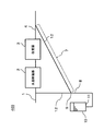
- FIG. 1 is a schematic diagram illustrating an example of a schematic configuration of the hydrogen generator according to the first embodiment.
- the hydrogen generator 100 of this embodiment includes a raw material supply path 1, a hydrodesulfurizer 2, a reformer 3, a recycle path 12, and a drainage path 8.
- the raw material supply path 1 is a flow path through which the raw material supplied to the hydrodesulfurizer 2 flows.
- the raw material supply path 1 connects, for example, a raw material supply source (not shown) and the hydrodesulfurizer 2.
- the hydrodesulfurizer 2 removes sulfur compounds in the raw material. More specifically, the sulfur compound in the raw material supplied to the reformer 3 is removed.
- the sulfur compound may be artificially added to the raw material as an odorous component, or may be a natural sulfur compound derived from the raw material itself.
- TBM tertiary-butylmercaptan
- DMS dimethyl sulfide
- THT tetrahydrothiophene
- COS carbonyl sulfide
- hydrogen sulfide hydrogen sulfide (hydrogen sulfide), etc.
- the hydrodesulfurizer 2 can be configured, for example, by filling a container with a hydrodesulfurization agent.
- a hydrodesulfurization agent for example, a CuZn-based catalyst having both a function of converting a sulfur compound into hydrogen sulfide and a function of adsorbing hydrogen sulfide is used.
- the hydrodesulfurization agent is not limited to this example.
- the reformer 3 generates a hydrogen-containing gas by a reforming reaction using raw materials.
- the raw material is, for example, a raw material containing an organic compound having at least carbon and hydrogen as constituent elements.
- Specific examples of the raw material include natural gas, city gas, hydrocarbons such as LPG and LNG, and alcohols such as methanol and ethanol.
- City gas refers to gas supplied from a gas company to households through piping.
- the reforming reaction may take any form, and examples thereof include a steam reforming reaction, an autothermal reaction, and a partial oxidation reaction.
- the reforming reaction is a steam reforming reaction
- a combustor (not shown) that heats the reformer 3
- an evaporator (not shown) that generates steam
- water that supplies water to the evaporator A feeder (not shown)
- the hydrogen generator 100 may be further provided with an air supply device (not shown) that supplies air to the reformer 3.
- a CO reducer that reduces carbon monoxide in the hydrogen-containing gas generated by the reformer 3 may be provided downstream of the reformer 3.
- the CO reducer includes, for example, at least one of a converter that reduces carbon monoxide by a shift reaction and a CO remover that reduces carbon monoxide by at least one of an oxidation reaction and a methanation reaction. Also good.
- the hydrogen-containing gas channel 4 is a channel through which the hydrogen-containing gas discharged from the reformer 3 flows.
- the recycling channel 12 has an upstream end connected to the hydrogen-containing gas channel 4 and a downstream end connected to the raw material supply channel 1.
- the upstream end of the recycle channel 12 is not necessarily connected to the hydrogen-containing gas channel 4, and the recycle channel 12 may be directly connected to the reformer 3.
- the upstream end of the recycle channel 12 may be directly connected to the CO reducer, or provided in the hydrogen-containing gas channel 4 downstream of the CO reducer. May be.
- the CO reducer includes a transformer and a CO remover
- the upstream end of the recycle flow path 12 may be connected to the flow path between the transformer and the CO reducer.
- the upstream end of the recycle flow path 12 may be connected to a flow path of exhaust gas containing hydrogen discharged from a hydrogen utilization device (for example, a fuel cell).
- downstream end of the recycle channel 12 is not necessarily connected to the raw material supply channel 1, and the recycle channel 12 may be directly connected to the hydrodesulfurizer 2.
- the downward gradient 7 is formed in a part of the recycling flow path 12, but the entire recycling flow path 12 may be downward gradient.
- the raw material inlet of the hydrodesulfurizer 2 is arranged below the hydrogen-containing gas outlet of the reformer 3 in the vertical direction.
- the descending gradient 7 is formed in at least a part of the recycle channel 12. That is, it is sufficient that the descending gradient 7 is formed in at least a part of the recycle channel 12. Part or all of the downward slope 7 may be part of the U-shaped tube.
- the recycle channel 12 is formed as a pipe, for example.
- the recycle channel 12 may be made of a metal such as stainless steel, for example.
- the recycle channel 12 may be provided with at least one of an on-off valve and a flow rate adjustment valve (not shown).
- the inclination ⁇ formed by the downward gradient 7 of the recycle channel 12 and the horizontal plane can be, for example, 5 degrees or more and 90 degrees or less. It is desirable that the inclination ⁇ formed by the descending slope 7 and the horizontal plane is 10 degrees or more and 90 degrees or less. It is desirable that the inclination ⁇ formed by the descending slope 7 and the horizontal plane is 15 degrees or more and 90 degrees or less.
- the flow direction of the hydrogen-containing gas coincides with the flow direction of the droplets generated by condensation inside the flow path. Since the effect of the gas flowing away the droplet is expected, the droplet can be caused to flow even when the inclination is less than the sliding angle of the droplet in a stationary state.
- the sliding speed of the droplet is low, the droplets generated on the inner surface of the pipe due to condensation can be united and grow into a large droplet.
- the droplets generated at the descending gradient 7 are prevented from entering the downstream side of the recycling flow path 12 beyond the branching portion to the drainage path 8 by the recycle gas. It can be smoothly led to the drainage channel 8.
- other means such as an obstacle plate for allowing droplets to flow down may be arranged at a branch portion from the descending slope 7 to the drainage channel 8.
- the drainage channel 8 drains the condensed water condensed in the recycle channel 12 with the downward slope 7.
- the drainage channel 8 is provided so as to branch at the downstream end of the downward gradient 7. With this configuration, the condensed water generated in the recycle channel 12 can be drained efficiently.
- the drainage channel 8 is not limited to the example shown in FIG. 1 and may be provided at any location as long as it is on the down-gradient recycling channel 12.
- the drainage channel 8 may be provided so as to branch from the middle of the downward gradient 7.
- the downstream end of the drainage channel 8 may be connected to, for example, a condensed water tank that stores condensed water.
- the downstream end of the drainage channel 8 may be connected to a drainage groove outside the hydrogen generator 100.
- the drainage channel 8 may be provided, for example, in a portion of the recycle channel 12 that extends in the horizontal direction from the downstream end of the downward gradient 7.
- the drainage path 8 may be provided in a part extending in the horizontal direction. That is, the drainage channel 8 may be provided in at least one of the downward gradient 7 of the recycle channel 12 and the recycle channel 12 on the downstream side of the downward gradient 7.
- the hydrogen-containing gas immediately after being discharged from the reformer 3 is high temperature (for example, 600 ° C.) and contains a large amount of water vapor.
- the hydrogen-containing gas flows through the inside of the recycle channel 12, the hydrogen-containing gas dissipates heat and the temperature decreases. As a result, condensed water that is liquid water is generated.
- the condensed water generated in the downward gradient 7 of the recycle channel 12 flows down the downward gradient 7 and is drained through the drainage channel 8.
- the downward slope 7 has a slope that goes down along the gas flow, and the direction of the gas flow and the direction of the flow of the condensed water is the same, so that the condensed water is drained from the recycle channel 12 more efficiently. it can. Therefore, compared with the conventional hydrogen generator provided with the condenser, the possibility that the recycle flow path 12 is blocked by the condensed water is reduced at a simpler and lower cost.
- the recycle channel 12 may be provided with a condenser or may not be provided. When a condenser is provided, condensed water is generated in the recycle flow path 12 configured as described above. Therefore, the recycle flow path 12 is smaller and simpler than the condenser of the conventional hydrogen generator. It becomes possible to suppress occlusion.
- the inclination ⁇ formed by the downward gradient 7 of the recycle channel 12 with respect to the horizontal plane is less than 90 degrees, for example, the following effects can be obtained. That is, the moisture condensed at the portion of the recycle channel 12 that has the downward gradient 7 becomes droplets.
- the inclination ⁇ between the flow path and the horizontal plane is 90 degrees, the entire circumferential direction inside the pipe may get wet.
- the flow path is inclined with respect to the horizontal plane at an inclination ⁇ of less than 90 degrees, the liquid droplet moves to the lower region inside the pipe and a part of the liquid becomes wet. For this reason, it is difficult for liquid droplets to stick to the wall surface inside the pipe to form a liquid film.
- the pipe diameter may be such that a water film due to surface tension is not formed so that water condensed in the pipe does not completely block the inside of the pipe.
- the pipe diameter of the downward gradient 7 may be, for example, 3 mm or more and 20 mm or less.
- the piping material has sufficient margin for the sliding angle of water determined by the condition of the inner surface of the piping, piping material, water viscosity, etc. so that water is drained only by gravity acting on the condensed water droplets. It may be an angle. It is good also as a pipe internal diameter from which a gas flow rate becomes 0.3 m / sec or less, and it is good also as an angle which is 10 degree
- the hydrogen generation device is the hydrogen generation device according to the first embodiment, in which the downward gradient of the recycle flow path is connected to the first flow path having the downward gradient and the first flow path. And a second channel inclined at an obtuse angle with respect to the one channel.
- the condensed water can easily flow smoothly without convection, and the condensed water can be drained from the recycling flow path more efficiently than when the bent portion is formed at an acute angle.
- the obtuse angle is an angle larger than 90 degrees and smaller than 180 degrees (hereinafter, the same applies to other embodiments). “Inclined at an obtuse angle with respect to the first channel” means that an angle formed by the first channel and the second channel is an obtuse angle.
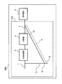
- FIG. 2 is a schematic diagram showing an example of a schematic configuration of the hydrogen generator according to the second embodiment.
- the hydrogen generator 200 of this embodiment can have the same configuration as the hydrogen generator 100 of the first embodiment, except that the configuration of the recycle channel 12 is different. Therefore, the same name and code
- the downward gradient of the recycle flow path is connected to the first flow path 7A extending vertically downward and the first flow path 7A, with respect to the first flow path 7A. And a second flow path 7B inclined at an obtuse angle ⁇ .
- the inclination ⁇ formed by the second flow path 7B with the horizontal plane can be 5 degrees or more and 90 degrees or less.
- the inclination ⁇ formed by the second flow path 7B and the horizontal plane is preferably 10 degrees or more and 90 degrees or less.
- the inclination ⁇ formed by the second flow path 7B with the horizontal plane is preferably 15 degrees or more and 90 degrees or less.
- the downstream portion of the second flow path 7B may extend in the horizontal direction.
- the drainage channel 8 may be provided in a downstream portion extending in the horizontal direction in the second channel 7B.
- the hydrogen-containing gas discharged from the reformer 3 contains water vapor, and condensation occurs when passing through the recycle flow path 12. At this time, the liquid droplets generated by the condensation travel down the gradient 7 and are guided to the drainage channel.
- the upstream portion where the distance from the reformer 3 is relatively close has a high saturated vapor pressure, the amount of condensed water increases, and the channel is likely to be blocked.
- the distance here refers to the length of the path through which the gas flows.
- the distance refers to the length of the pipe when the recycle channel 12 is formed of a pipe.
- the inclination that the first flow path 7A forms with the horizontal plane is not necessarily 90 degrees, and may be an angle that is larger than ⁇ and smaller than 90 degrees, for example.
- the angle formed by the hydrogen-containing gas flow path 4 and the first flow path 7A is 90 degrees, but may be an obtuse angle.
- the slope formed by the downward slope 7 of the recycle channel 12 and the horizontal plane may be reduced as the distance from the reformer 3 is increased.
- the discontinuous bent portion is not essential, and the inclination formed by the descending slope 7 of the recycle channel 12 with the horizontal plane may be continuously reduced as the distance from the reformer 3 increases.
- at least a part of the recycling flow path may be formed in a spiral shape. Even with such a configuration, it is possible to efficiently drop the droplets due to gravity in the upstream portion of the downward gradient 7. In the downstream side portion of the downward gradient 7, the droplets grow large, so that the dew condensation generated in the downward gradient 7 can be smoothly guided to the drainage channel 8.
- a part of the downward slope 7 may extend in the horizontal direction.
- a drainage channel 8 may be provided in a portion extending in the horizontal direction on the downward gradient 7.
- Part or all of the downward slope 7 may be part of the U-shaped tube.
- the hydrogen generation device according to the third embodiment is the hydrogen generation device according to any one of the first embodiment and the second embodiment, and the recycle channel is formed with an ascending gradient after a descending gradient is formed. .
- the branch point of the drainage channel is arranged at a higher position, and the recycling channel can be downsized in the vertical direction.
- the upward gradient of the recycle flow path is connected to the second flow path, and the third flow path is inclined at an obtuse angle with respect to the second flow path.
- a fourth channel that is connected to the channel, is inclined at an obtuse angle with respect to the third channel, and has an upward slope may be provided.
- the angle formed by the bent portion of the recycling flow path is an obtuse angle, gas turbulence is less likely to occur in the bent portion, and the condensed water can be drained from the recycling flow path more efficiently.
- the drainage channel may be branched from the recycle channel at the connection between the second channel and the third channel.
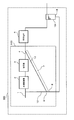
- FIG. 3 is a schematic diagram showing an example of a schematic configuration of the hydrogen generator according to the third embodiment.
- the hydrogen generator 300 of the present embodiment can have the same configuration as the hydrogen generator 100 of the first embodiment, except that the configuration of the recycle channel 12 is different. Therefore, the same name and code
- the downward gradient 7 of the recycle flow path is connected to the first flow path 7A that extends vertically downward and the first flow path 7A, with respect to the first flow path 7A.
- the upward gradient 17 of the recycle flow path is connected to the second flow path 7B, and the third flow path 17A is inclined with an obtuse angle ⁇ with respect to the second flow path 7B.
- the fourth channel 17B is connected to the third channel 17A, is inclined at an obtuse angle ⁇ with respect to the third channel 17A, and extends vertically upward.
- the inclination ⁇ formed by the second flow path 7B with the horizontal plane can be 5 degrees or more and 90 degrees or less.
- the inclination ⁇ formed by the second flow path 7B and the horizontal plane is preferably 10 degrees or more and 90 degrees or less.
- the inclination ⁇ formed by the second flow path 7B with the horizontal plane is preferably 15 degrees or more and 90 degrees or less.
- the inclination ⁇ formed by the third flow path 17A with the horizontal plane can be 5 degrees or more and 90 degrees or less.
- the inclination ⁇ formed by the third flow path 17A with the horizontal plane is preferably 10 degrees or more and 90 degrees or less.
- the inclination ⁇ formed by the third flow path 17A with the horizontal plane is preferably 15 degrees or more and 90 degrees or less.
- the inclination ⁇ formed by the second flow path 7B with the horizontal plane and the inclination ⁇ formed by the third flow path 17A with the horizontal plane may be ⁇ ⁇ .
- the flow direction of the second flow path 7B having a downward gradient is opposite to the flow direction of the liquid droplet, so that the liquid droplet is caused by the drag generated by the gas flow. It becomes difficult to flow down.
- the hydrogen-containing gas flowing through the recycle channel 12 contains a lot of steam on the upstream side. Therefore, in order to drain the water droplets, first, the hydrogen-containing gas passes through the downward gradient 7. The water droplets that slide down the descending slope 7 reach the branching portion that branches into the drainage channel 8, flow down vertically by gravity, and are introduced into the drainage channel 8. On the other hand, the hydrogen-containing gas that has passed through the branching portion that branches into the drainage channel 8 still contains water vapor, so that condensation occurs in the recycling channel. Therefore, after the hydrogen-containing gas passes through the branch portion, an ascending gradient 17 is provided to guide droplets generated by condensation to the drainage channel 8.
- the said branch part becomes the lowest part in the part through which the hydrogen containing gas containing water vapor
- the ascending gradient 17 and the descending gradient 7 may constitute the entire recycle channel 12 or a part of the recycle channel 12.
- a part or all of the upward gradient 17 may be a part of a U-shaped tube.
- a U-shaped tube may be configured by a part or all of the ascending gradient 17 and a part or all of the descending gradient 7.
- At least a part of the descending gradient 7 and the ascending gradient 12 may be installed in the middle of the ventilation path in the system housing in which the reformer and the fuel cell are stored, and may be configured to be cooled by the flow of ventilation air. If at least one of the descending slope 7 and the ascending slope 12 is arranged on the ventilation path connecting the intake port and the exhaust port in the system housing, the cooling is more efficiently performed, and the discharge efficiency of the condensed water is improved. desirable.
- FIG. 4 is a cross-sectional view showing an example of a schematic configuration in the vicinity of the drainage channel in the hydrogen generator according to the third embodiment.
- the droplet 14 generated by the dew condensation at the downward slope 7 is guided to the drainage channel 8 through the branching portion to the drainage channel 8. Thereafter, the recycle gas proceeds on the upward gradient 17. Since the droplets generated by the dew condensation on the downward gradient 7 are removed, the vapor pressure of the recycle gas is reduced, but still contains water vapor. For this reason, dew condensation occurs inside the ascending slope 17, and condensed water 15 is generated.
- the condensate 15 in the ascending gradient 17 is subjected to a drag in the direction opposite to that caused by gravity due to the flow of the recycle gas. Due to this drag, the flow of the condensed water 15 is hindered, and the possibility that the flow path is blocked by the condensed water increases.
- the inner diameter of the pipes constituting the ascending gradient 17 may be increased so that the flow rate of the recycle gas flowing through the ascending gradient 17 is reduced to the flow velocity at which the condensed water flows down on the ascending gradient 17.
- the inner diameter of the pipe constituting the ascending gradient 17 may be set so that the gas flow rate is greater than 0 m / sec and equal to or less than 1 m / sec.
- the inner diameter of the pipe constituting the ascending gradient 17 is desirably set so that the gas flow rate is greater than 0 m / sec and equal to or less than 0.6 m / sec. It is desirable to set the gas flow rate to be greater than 0 m / sec and less than or equal to 0.3 m / sec.
- the gas flow rate is a gas flow rate when the hydrogen generation amount of the hydrogen generator 100 is maximum.
- the inclination angle of the ascending slope may be set so that the force by which the condensate of the ascending slope 17 slides down is increased to a magnitude that flows down against the flow of the recycle gas.
- the inclination ⁇ formed with the horizontal plane may be 15 degrees or more and 90 degrees or less.
- the recycle gas After draining the droplets generated in the ascending gradient 17, the recycle gas is connected to the fourth channel 17B that is vertically upward at the downstream end of the third channel 17A.
- the recycle gas that has reached the fourth flow path 17B has already reduced its vapor pressure by generating condensed water.
- the fourth flow channel 17B is not provided with a gradient so that the droplet slides down on the wall surface of the flow channel, but rather, the droplet fine particles generated in the gas flow without contacting the wall surface of the flow channel. It may be installed vertically upward so as to fall inside the road.
- the connecting portion between the ascending gradient 17 and the descending gradient 7 is the lowermost part in the recycling flow path.
- the hydrogen generator of the fourth embodiment is any one of the hydrogen generator of the first embodiment, the second embodiment, and the third embodiment, and the downstream end of the drainage channel is sealed with water.
- downstream end of the drainage channel is sealed with water includes both cases where the downstream end of the drainage channel is directly or indirectly sealed with water. Indirectly water-sealed is exemplified by a case where the water is sealed with a sealed space in between.
- FIG. 5 is a schematic diagram showing an example of a schematic configuration of the hydrogen generator according to the fourth embodiment.
- the hydrogen generator 400 of this embodiment can have the same configuration as the hydrogen generator 100 of the first embodiment, except that the drainage channel 8 is sealed with water. Therefore, the same name and code
- FIG. 6 is a cross-sectional view showing an example of a schematic configuration near the tank in the hydrogen generator according to the fourth embodiment.
- the water tank 10 is connected to the drainage channel 8
- the drainage channel 8 is connected to the drainage channel below the water surface of the water tank 10. 8 is sealed with water.
- the water tank 10 may be shared with other water storage tanks.
- a tank for storing water recovered from the exhaust gas of the fuel cell a tank for storing cooling water for cooling the fuel cell, and the like can be mentioned.
- a drain port (not shown) may be formed in the tank. In this case, for example, it may be a drainage port (overflow port) through which water overflowing from the tank is drained.
- a drain outlet may be provided below the water surface of the tank, and drainage may be performed by appropriately opening a valve provided in a drain passage (not shown) connected to the drain outlet.
- the configuration of the water sealer or the water seal means is not limited to the water tank 10 and may be other configurations.
- the downstream end of the drainage channel 8 may be sealed with a U-shaped tube.
- the above is an example of a configuration in which the downstream end of the drainage channel 8 is directly sealed with water.
- a tank for storing water drained from the downstream end of the drainage channel 8 is provided below the drainage channel 8.
- the form provided above the water surface of the tank is mentioned.
- the fuel cell system according to the fifth embodiment includes a hydrogen generator according to any one of the first embodiment, the second embodiment, the third embodiment, and the fourth embodiment, and a hydrogen-containing gas supplied from the hydrogen generator. And a fuel cell for generating electricity.
- FIG. 7 is a conceptual diagram showing an example of a schematic configuration of a fuel cell system according to the fifth embodiment.
- the fuel cell system 500 of the present embodiment includes the hydrogen generator 100 of the first embodiment and the fuel cell 6. Since the configuration of the hydrogen generator 100 can be the same as that of the first embodiment, the same reference numerals and names are used for the same components in FIG. 7 and FIG. .
- the hydrogen generator may be any of the hydrogen generators of the first embodiment, the second embodiment, the third embodiment, the fourth embodiment, and modifications thereof.
- the fuel cell 6 generates power using the hydrogen-containing gas supplied from the hydrogen generator.
- the fuel cell may be of any type, and examples include a polymer electrolyte fuel cell, a solid oxide fuel cell, and a phosphoric acid fuel cell.
- the reformer 3 and the fuel cell 6 in the hydrogen generator 100 are configured to be built in one container.
- the fuel cell system according to the sixth embodiment is the fuel cell system according to the fifth embodiment.
- the fuel cell system includes a water tank that stores moisture in the exhaust gas discharged from the fuel cell system, and the drainage channel is water below the water surface of the water tank. Connected with tank.
- a water tank normally provided in the fuel cell system is used to realize water sealing of the drainage channel, so that the configuration can be further simplified as compared with the case where the water tank is not used.
- the exhaust gas discharged in the fuel cell system is obtained by burning off-oxidant gas discharged from the fuel cell, off-fuel gas discharged from the fuel cell, and off-fuel gas discharged from the fuel cell, for example. It can be at least one of combustion exhaust gas.
- FIG. 8 is a conceptual diagram showing an example of a schematic configuration of the fuel cell system according to the sixth embodiment.
- the fuel cell system 600 includes the hydrogen generator 100 of the first embodiment, the fuel cell 6, and the water tank 19. Since the configuration of the hydrogen generator 100 can be the same as that of the first embodiment, the same reference numerals and names are used for the same components in FIG. 8 and FIG. .
- the hydrogen generator may be any one of the hydrogen generators of the first embodiment, the second embodiment, the third embodiment, the fourth embodiment, and their modifications.
- the fuel cell 6 can be the same as the fuel cell 6 of the fifth embodiment, a detailed description thereof will be omitted.
- the water tank 19 stores moisture in the exhaust gas discharged from the fuel cell system 600.
- the water tank 19 is a water tank that stores moisture in the off-fuel gas discharged from the fuel cell 6.
- the off fuel gas discharged from the water tank 19 is discharged to the outside of the fuel cell system 600.
- the off fuel gas is supplied to a combustor (not shown). It may be burned.
- the drainage channel 8 is connected to the bottom of the water tank 19, but is not limited to this example. As long as it is below the water surface of the water tank 19, it may be connected to any location. Specifically, the drainage channel 8 may be connected to the side surface of the water tank 19.
- the lower end of the drainage channel 8 configured as described above is always sealed with water.
- the hydrogen-containing gas that has passed through the downward gradient 7 does not flow into the drainage channel 8 but smoothly flows into the recycle channel 12 on the downstream side of the branch portion 9. Accordingly, the possibility that the hydrogen-containing gas leaks outside through the drainage channel 8 and comes into contact with the outside air is reduced.
- the hydrogen-containing gas can be sent stably to the hydrodesulfurizer.
- the drainage channel 8 When the fuel cell system 600 is continuously operated, condensed water accumulates in the drainage channel 8 and needs to be discharged periodically.
- the pressure inside the recycling pipe may fluctuate due to a change in the water level, and the flow rate of the recycling gas may vary.
- the drainage channel 8 communicates with the water tank 19 and drains from both the drainage channel 8 and the water tank 19. Water surface fluctuations are suppressed. Thereby, the pressure fluctuation in the recycling flow path 12 can be suppressed, and the hydrogen-containing gas can be stably supplied to the hydrodesulfurizer.
- the fuel cell system according to this embodiment is the same as the fuel cell system according to the sixth embodiment, in which the on-off valve provided in the recycle channel and the water surface of the water tank are positioned above the connection between the drainage channel and the water tank. And a controller that opens the on-off valve after water filling is performed.
- the hydrogen-containing gas flows through the recycle gas channel, so that the possibility that the hydrogen-containing gas leaks outside through the drainage channel and comes into contact with the outside air is reduced.
- the hydrogen-containing gas can be sent stably to the hydrodesulfurizer.
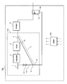
- FIG. 9 is a conceptual diagram showing an example of a schematic configuration of a fuel cell system according to the seventh embodiment.
- the fuel cell system 700 includes the hydrogen generator 100, the fuel cell 6, the water tank 19, and the controller 20.
- generation apparatus 100 since it can be the same as that of 1st Embodiment except the on-off valve 21 being provided in the recycle flow path 12, about the component which is common in FIG. 9 and FIG. Are denoted by the same reference numerals and names, and detailed description thereof is omitted.
- the hydrogen generation apparatus is one of the first embodiment, the second embodiment, the third embodiment, the fourth embodiment, and their modifications, except that the on-off valve 21 is provided in the recycle channel 12.
- a configuration similar to that of the hydrogen generator may be employed.
- the fuel cell 6 may be the same as the fuel cell 6 of the fifth embodiment.
- the water tank 19 may be the same as the water tank 19 of the sixth embodiment.
- the on-off valve 21 is an on-off valve provided in the recycle channel. The on-off valve 21 is connected to the controller 20 in a communicable manner.
- the controller 20 opens the on-off valve 21 after water filling is performed so that the water surface of the water tank 19 is positioned above the connecting portion 18 between the drainage channel 8 and the water tank 19.
- the controller 20 only needs to have a control function, and includes, for example, an arithmetic processing unit (not shown) and a storage unit (not shown) that stores a control program. Examples of the arithmetic processing unit include an MPU and a CPU. An example of the storage unit is a memory.
- the controller may be composed of a single controller that performs centralized control, or may be composed of a plurality of controllers that perform distributed control in cooperation with each other.
- FIG. 10 is a flowchart showing an example of an operation method of the fuel cell system according to the seventh embodiment. Such an operation method can be executed under the control of the controller 20.
- step S101 the controller 20 closes the on-off valve 21 (step S101). Note that this step may be omitted if the on-off valve 21 has already been closed before activation.
- the controller 20 performs water filling so that the water surface of the water tank 19 is positioned above the connection portion between the drainage channel 8 and the water tank 19 (step S102).
- the controller 20 opens the on-off valve 21 at a predetermined timing (step S104).
- the predetermined timing is at least after the generation of the hydrogen-containing gas is started in the reformer 3.
- the on-off valve 21 is opened, there is a possibility that the recycle gas flows into the drainage channel 8 and the hydrogen-containing gas flowing into the hydrodesulfurizer 2 is insufficient. Therefore, before opening the on-off valve 21 and allowing the hydrogen-containing gas to flow through the recycle channel 12, the water tank 19 is filled with water, and after the water-sealed structure is secured, the on-off valve 21 is opened to allow the hydrogen-containing gas to flow. .
- the hydrogen-containing gas can be stably supplied to the hydrodesulfurizer.
- the present invention since it is simplified and cost-reduced as compared with the prior art, it is useful as a hydrogen generator and a fuel cell system.
Landscapes
- Chemical & Material Sciences (AREA)
- Chemical Kinetics & Catalysis (AREA)
- Engineering & Computer Science (AREA)
- Organic Chemistry (AREA)
- General Chemical & Material Sciences (AREA)
- Sustainable Energy (AREA)
- Sustainable Development (AREA)
- Electrochemistry (AREA)
- Life Sciences & Earth Sciences (AREA)
- Manufacturing & Machinery (AREA)
- Health & Medical Sciences (AREA)
- General Health & Medical Sciences (AREA)
- Combustion & Propulsion (AREA)
- Inorganic Chemistry (AREA)
- Fuel Cell (AREA)
- Hydrogen, Water And Hydrids (AREA)
Abstract
Description
第1実施形態の水素生成装置は、原料を用いて改質反応により水素含有ガスを生成する改質器と、原料中の硫黄化合物を除去する水添脱硫器と、水添脱硫器に流入する前の原料に添加される水素含有ガスが流れるとともに下り勾配が形成されているリサイクル流路と、下り勾配のリサイクル流路において凝縮した凝縮水を排水する排水路とを備える。
図1は、第1実施形態にかかる水素生成装置の概略構成の一例を示す模式図である。
第2実施形態の水素生成装置は、第1実施形態の水素生成装置であって、リサイクル流路の下り勾配は、下り勾配の第1の流路と、第1の流路に接続され、第1の流路に対して鈍角に傾斜する第2の流路とを備えている。
第3実施形態の水素生成装置は、第1実施形態及び第2実施形態のいずれかの水素生成装置であって、リサイクル流路は、下り勾配が形成された後、上り勾配が形成されている。
(第4実施形態)
第4実施形態の水素生成装置は、第1実施形態、第2実施形態、及び第3実施形態のいずれかの水素生成装置であって、排水路の下流端は水封されている。
第5実施形態の燃料電池システムは、第1実施形態、第2実施形態、第3実施形態、及び第4実施形態のいずれかの水素生成装置と、水素生成装置より供給される水素含有ガスを用いて発電する燃料電池とを備える。
第6実施形態の燃料電池システムは、第5実施形態の燃料電池システムにおいて、燃料電池システムにおいて排出される排ガス中の水分を貯える水タンクを備え、排水路が、水タンクの水面より下方において水タンクと接続されている。
本実施形態の燃料電池システムは、第6実施形態の燃料電池システムにおいて、リサイクル流路に設けられた開閉弁と、水タンクの水面が、排水路と水タンクとの接続部よりも上方に位置するよう水張りが行われた後、開閉弁を開放する制御器とを備える。
2 水添脱硫器
3 改質器
4 水素含有ガス流路
6 燃料電池
7 下り勾配
7A 第1の流路
7B 第2の流路
8 排水路
9 分岐部
10 タンク
11 接続部
12 リサイクル流路
14 液滴
15 液滴
17 上り勾配
17A 第3の流路
17B 第4の流路
18 接続部
19 水タンク
20 制御器
21 開閉弁
100 水素生成装置
200 水素生成装置
300 水素生成装置
400 水素生成装置
500 燃料電池システム
600 燃料電池システム
700 燃料電池システム
Claims (9)
- 原料を用いて改質反応により水素含有ガスを生成する改質器と、原料中の硫黄化合物を除去する水添脱硫器と、前記水添脱硫器に流入する前の原料に添加される水素含有ガスが流れるとともに下り勾配が形成されているリサイクル流路と、下り勾配の前記リサイクル流路において凝縮した凝縮水を排水する排水路とを備える、水素生成装置。
- 前記リサイクル流路の下り勾配は、下り勾配の第1の流路と、前記第1の流路に接続され、前記第1の流路に対して鈍角に傾斜する第2の流路とを備えている、請求項1に記載の水素生成装置。
- 前記リサイクル流路は、前記下り勾配が形成された後、上り勾配が形成されている、請求項1または2記載の水素生成装置。
- 前記リサイクル流路の上り勾配は、前記第2の流路に接続され、前記第2の流路に対して鈍角に傾斜する第3の流路と、前記第3の流路に接続され、前記第3の流路に対して鈍角に傾斜し、上り勾配の第4の流路とを備えている、請求項3記載の水素生成装置。
- 前記排水路は、前記第2の流路と前記第3の流路との接続部で前記リサイクル流路より分岐している、請求項4記載の水素生成装置。
- 前記排水路の下流端は水封されている、請求項1-5のいずれかに記載の水素生成装置。
- 請求項1-6のいずれかに記載の水素生成装置と、前記水素生成装置より供給される水素含有ガスを用いて発電する燃料電池とを備える燃料電池システム。
- 前記燃料電池システムにおいて排出される排ガス中の水分を貯える水タンクを備え、前記排水路が、前記水タンクの水面より下方において前記水タンクと接続されている、請求項7記載の燃料電池システム。
- 前記リサイクル流路に設けられた開閉弁と、前記水タンクの水面が、前記排水路と前記水タンクとの接続部よりも上方に位置するよう水張りが行われた後、前記開閉弁を開放する制御器とを備える、請求項8記載の燃料電池システム。
Priority Applications (2)
| Application Number | Priority Date | Filing Date | Title |
|---|---|---|---|
| US14/389,952 US9437891B2 (en) | 2012-04-19 | 2013-04-19 | Hydrogen generator and fuel cell system |
| EP13778085.4A EP2840061B1 (en) | 2012-04-19 | 2013-04-19 | Hydrogen generation device and fuel cell system |
Applications Claiming Priority (2)
| Application Number | Priority Date | Filing Date | Title |
|---|---|---|---|
| JP2012-095680 | 2012-04-19 | ||
| JP2012095680 | 2012-04-19 |
Publications (1)
| Publication Number | Publication Date |
|---|---|
| WO2013157274A1 true WO2013157274A1 (ja) | 2013-10-24 |
Family
ID=49383244
Family Applications (1)
| Application Number | Title | Priority Date | Filing Date |
|---|---|---|---|
| PCT/JP2013/002648 Ceased WO2013157274A1 (ja) | 2012-04-19 | 2013-04-19 | 水素生成装置及び燃料電池システム |
Country Status (4)
| Country | Link |
|---|---|
| US (1) | US9437891B2 (ja) |
| EP (1) | EP2840061B1 (ja) |
| JP (10) | JPWO2013157274A1 (ja) |
| WO (1) | WO2013157274A1 (ja) |
Cited By (5)
| Publication number | Priority date | Publication date | Assignee | Title |
|---|---|---|---|---|
| JP2017062973A (ja) * | 2015-09-25 | 2017-03-30 | アイシン精機株式会社 | 燃料電池システム |
| JP2018035061A (ja) * | 2012-04-19 | 2018-03-08 | パナソニックIpマネジメント株式会社 | 水素生成装置及び燃料電池システム |
| JP2018073627A (ja) * | 2016-10-28 | 2018-05-10 | パナソニックIpマネジメント株式会社 | 燃料電池システム |
| JP2019040762A (ja) * | 2017-08-25 | 2019-03-14 | アイシン精機株式会社 | 燃料電池システム |
| JP2022123553A (ja) * | 2021-02-12 | 2022-08-24 | 株式会社デンソー | 水素生成装置および燃料電池システム |
Families Citing this family (3)
| Publication number | Priority date | Publication date | Assignee | Title |
|---|---|---|---|---|
| US10770741B2 (en) | 2016-08-31 | 2020-09-08 | Toshiba Energy Systems & Solutions Corporation | Fuel cell module with hydrodesulfurizer and preheating |
| KR102580065B1 (ko) * | 2021-05-06 | 2023-09-19 | (주)이노시스 | 수소호흡발생기 구동 제어 시스템 |
| CN114471070B (zh) * | 2022-02-18 | 2023-05-16 | 广东韶钢松山股份有限公司 | 一种冷凝液收集单元及制酸系统 |
Citations (9)
| Publication number | Priority date | Publication date | Assignee | Title |
|---|---|---|---|---|
| JP2003017109A (ja) | 2001-03-28 | 2003-01-17 | Osaka Gas Co Ltd | 固体高分子型燃料電池発電システム及び固体高分子型燃料電池発電方法 |
| JP2003031245A (ja) * | 2001-07-13 | 2003-01-31 | Honda Motor Co Ltd | 燃料電池の加湿システム |
| JP2004060729A (ja) * | 2002-07-26 | 2004-02-26 | Osaka Gas Co Ltd | ドレイン抜き装置 |
| JP2005206414A (ja) * | 2004-01-22 | 2005-08-04 | Matsushita Electric Ind Co Ltd | 水素生成装置 |
| JP2006104003A (ja) * | 2004-10-04 | 2006-04-20 | Fuji Electric Holdings Co Ltd | 燃料改質システム |
| JP2006213566A (ja) * | 2005-02-04 | 2006-08-17 | Matsushita Electric Ind Co Ltd | 水素生成器 |
| JP2008251447A (ja) * | 2007-03-30 | 2008-10-16 | Ihi Corp | 燃料電池発電装置のドレン処理装置 |
| JP2009043527A (ja) * | 2007-08-08 | 2009-02-26 | Panasonic Corp | 燃料電池システム |
| JP2011113918A (ja) * | 2009-11-30 | 2011-06-09 | Toshiba Corp | 燃料電池システム |
Family Cites Families (33)
| Publication number | Priority date | Publication date | Assignee | Title |
|---|---|---|---|---|
| JP2920297B2 (ja) * | 1989-09-22 | 1999-07-19 | ヤマハ発動機株式会社 | 燃料電池発電装置 |
| JP2842517B2 (ja) * | 1994-12-27 | 1999-01-06 | 三菱電機株式会社 | 燃料電池発電設備 |
| US5686196A (en) | 1996-10-09 | 1997-11-11 | Westinghouse Electric Corporation | System for operating solid oxide fuel cell generator on diesel fuel |
| JP2002042847A (ja) * | 2000-07-26 | 2002-02-08 | Toshiba Corp | 固体高分子型燃料電池システム |
| JP4036607B2 (ja) * | 2000-09-25 | 2008-01-23 | 三洋電機株式会社 | 燃料ガス改質装置及び燃料電池システム |
| JP4493257B2 (ja) * | 2001-03-26 | 2010-06-30 | 大阪瓦斯株式会社 | 燃料改質システム |
| JP4162422B2 (ja) * | 2001-04-24 | 2008-10-08 | 大阪瓦斯株式会社 | 燃料改質システム |
| JP3753055B2 (ja) * | 2001-11-27 | 2006-03-08 | トヨタ自動車株式会社 | 気液分離装置 |
| JP2003197245A (ja) * | 2001-12-27 | 2003-07-11 | Toyota Motor Corp | 燃料電池 |
| JP4304975B2 (ja) * | 2002-12-18 | 2009-07-29 | 富士電機ホールディングス株式会社 | 燃料電池発電装置 |
| JP2004213566A (ja) * | 2003-01-08 | 2004-07-29 | Imobile Inc | 勤務シフト変更依頼システム、勤務シフト変更依頼方法 |
| JP2005071926A (ja) * | 2003-08-27 | 2005-03-17 | Matsushita Electric Ind Co Ltd | 燃料電池システム |
| US7892511B2 (en) * | 2004-07-02 | 2011-02-22 | Kellogg Brown & Root Llc | Pseudoisothermal ammonia process |
| JP2006120522A (ja) * | 2004-10-22 | 2006-05-11 | Babcock Hitachi Kk | 燃料電池システム |
| JP2006164837A (ja) * | 2004-12-09 | 2006-06-22 | Toshiba Fuel Cell Power Systems Corp | 固体高分子型燃料電池システム |
| PL1843840T3 (pl) * | 2005-01-06 | 2019-11-29 | Res Triangle Inst | Sorbenty na bazie tlenku cynku oraz procesy ich wytwarzania i stosowania |
| JP2006206947A (ja) * | 2005-01-27 | 2006-08-10 | Nisshin Steel Co Ltd | 固体高分子型燃料電池システム用ステンレス鋼製接水部材 |
| JP2006278117A (ja) * | 2005-03-29 | 2006-10-12 | Ishikawajima Harima Heavy Ind Co Ltd | 固体高分子型燃料電池発電装置 |
| JP4087877B2 (ja) * | 2006-05-10 | 2008-05-21 | アイシン精機株式会社 | 燃料電池システム |
| KR20080053886A (ko) * | 2006-12-11 | 2008-06-16 | 후지 덴키 홀딩스 가부시키가이샤 | 연료전지 발전장치 |
| JP2008198400A (ja) * | 2007-02-08 | 2008-08-28 | Toshiba Fuel Cell Power Systems Corp | 燃料電池発電システム |
| JP2009016151A (ja) * | 2007-07-04 | 2009-01-22 | Ihi Corp | 燃料電池発電装置のドレン回収装置 |
| WO2009047897A1 (ja) * | 2007-10-11 | 2009-04-16 | Panasonic Corporation | 燃料電池システム |
| EP2228342B1 (en) * | 2008-01-09 | 2014-11-05 | Panasonic Corporation | Method of operating a hydrogen generation apparatus and fuel battery system |
| CA2718082C (en) * | 2008-03-14 | 2013-09-17 | Cosmo Oil Co., Ltd. | Method of extracting contents from the inside of a reactor kept at high temperature and high pressure, and synthesis reaction system of hydrocarbon compound |
| KR20110016432A (ko) * | 2008-05-22 | 2011-02-17 | 유티씨 파워 코포레이션 | 처리기 원료 가압 장치의 상류에 적용되는 수력 탈황기 재순환 |
| JP2010129454A (ja) * | 2008-11-28 | 2010-06-10 | Mitsubishi Electric Corp | 燃料電池ユニット |
| CN102395523B (zh) | 2009-12-25 | 2015-04-22 | 松下电器产业株式会社 | 氢生成装置和燃料电池系统 |
| JP5588689B2 (ja) * | 2010-02-01 | 2014-09-10 | 大阪瓦斯株式会社 | 固体酸化物形燃料電池 |
| JP5818227B2 (ja) * | 2010-10-25 | 2015-11-18 | 日産自動車株式会社 | 燃料電池システム |
| EP2637241B1 (en) * | 2011-05-06 | 2014-11-12 | Panasonic Corporation | Power generation system, and method for operating same |
| EP2840061B1 (en) * | 2012-04-19 | 2021-09-15 | Panasonic Intellectual Property Management Co., Ltd. | Hydrogen generation device and fuel cell system |
| JP2017163672A (ja) * | 2016-03-08 | 2017-09-14 | 富士電機株式会社 | 電力変換装置および電力変換装置の制御方法 |
-
2013
- 2013-04-19 EP EP13778085.4A patent/EP2840061B1/en active Active
- 2013-04-19 US US14/389,952 patent/US9437891B2/en active Active
- 2013-04-19 JP JP2014511116A patent/JPWO2013157274A1/ja active Pending
- 2013-04-19 WO PCT/JP2013/002648 patent/WO2013157274A1/ja not_active Ceased
-
2017
- 2017-04-04 JP JP2017074740A patent/JP6369731B2/ja active Active
- 2017-06-30 JP JP2017128610A patent/JP6410160B2/ja active Active
- 2017-08-28 JP JP2017163672A patent/JP2018035061A/ja active Pending
- 2017-08-28 JP JP2017163684A patent/JP6252963B1/ja active Active
- 2017-08-28 JP JP2017163680A patent/JP6350956B2/ja active Active
- 2017-10-03 JP JP2017193588A patent/JP6252964B1/ja active Active
- 2017-12-28 JP JP2017253956A patent/JP6473956B2/ja active Active
-
2018
- 2018-04-19 JP JP2018080622A patent/JP6478178B2/ja active Active
- 2018-04-24 JP JP2018083117A patent/JP2018160458A/ja active Pending
Patent Citations (9)
| Publication number | Priority date | Publication date | Assignee | Title |
|---|---|---|---|---|
| JP2003017109A (ja) | 2001-03-28 | 2003-01-17 | Osaka Gas Co Ltd | 固体高分子型燃料電池発電システム及び固体高分子型燃料電池発電方法 |
| JP2003031245A (ja) * | 2001-07-13 | 2003-01-31 | Honda Motor Co Ltd | 燃料電池の加湿システム |
| JP2004060729A (ja) * | 2002-07-26 | 2004-02-26 | Osaka Gas Co Ltd | ドレイン抜き装置 |
| JP2005206414A (ja) * | 2004-01-22 | 2005-08-04 | Matsushita Electric Ind Co Ltd | 水素生成装置 |
| JP2006104003A (ja) * | 2004-10-04 | 2006-04-20 | Fuji Electric Holdings Co Ltd | 燃料改質システム |
| JP2006213566A (ja) * | 2005-02-04 | 2006-08-17 | Matsushita Electric Ind Co Ltd | 水素生成器 |
| JP2008251447A (ja) * | 2007-03-30 | 2008-10-16 | Ihi Corp | 燃料電池発電装置のドレン処理装置 |
| JP2009043527A (ja) * | 2007-08-08 | 2009-02-26 | Panasonic Corp | 燃料電池システム |
| JP2011113918A (ja) * | 2009-11-30 | 2011-06-09 | Toshiba Corp | 燃料電池システム |
Non-Patent Citations (1)
| Title |
|---|
| See also references of EP2840061A4 * |
Cited By (6)
| Publication number | Priority date | Publication date | Assignee | Title |
|---|---|---|---|---|
| JP2018035061A (ja) * | 2012-04-19 | 2018-03-08 | パナソニックIpマネジメント株式会社 | 水素生成装置及び燃料電池システム |
| JP2017062973A (ja) * | 2015-09-25 | 2017-03-30 | アイシン精機株式会社 | 燃料電池システム |
| JP2018073627A (ja) * | 2016-10-28 | 2018-05-10 | パナソニックIpマネジメント株式会社 | 燃料電池システム |
| JP2019040762A (ja) * | 2017-08-25 | 2019-03-14 | アイシン精機株式会社 | 燃料電池システム |
| JP2022123553A (ja) * | 2021-02-12 | 2022-08-24 | 株式会社デンソー | 水素生成装置および燃料電池システム |
| JP7400751B2 (ja) | 2021-02-12 | 2023-12-19 | 株式会社デンソー | 水素生成装置および燃料電池システム |
Also Published As
| Publication number | Publication date |
|---|---|
| EP2840061A1 (en) | 2015-02-25 |
| JP6350956B2 (ja) | 2018-07-04 |
| JP2018150233A (ja) | 2018-09-27 |
| JP2018027887A (ja) | 2018-02-22 |
| JP6478178B2 (ja) | 2019-03-06 |
| US20150072253A1 (en) | 2015-03-12 |
| JP2018095549A (ja) | 2018-06-21 |
| JP6252963B1 (ja) | 2017-12-27 |
| JP2018024576A (ja) | 2018-02-15 |
| JP2018052808A (ja) | 2018-04-05 |
| JP2017200870A (ja) | 2017-11-09 |
| EP2840061B1 (en) | 2021-09-15 |
| US9437891B2 (en) | 2016-09-06 |
| JPWO2013157274A1 (ja) | 2015-12-21 |
| JP6410160B2 (ja) | 2018-10-24 |
| JP6252964B1 (ja) | 2017-12-27 |
| JP2018008874A (ja) | 2018-01-18 |
| EP2840061A4 (en) | 2015-05-20 |
| JP6473956B2 (ja) | 2019-02-27 |
| JP2018035061A (ja) | 2018-03-08 |
| JP6369731B2 (ja) | 2018-08-08 |
| JP2018160458A (ja) | 2018-10-11 |
Similar Documents
| Publication | Publication Date | Title |
|---|---|---|
| JP6478178B2 (ja) | 水素生成装置及び燃料電池システム | |
| JP6706742B2 (ja) | 燃料電池システム | |
| EP3028991A1 (en) | Hydrogen generator and fuel cell system | |
| JP2013184844A (ja) | 水素生成装置およびこれを備えた燃料電池システム | |
| JP2012204330A (ja) | 燃料電池発電装置及びその停止方法 | |
| JP6319555B2 (ja) | 水素生成装置及び燃料電池システム及び水素生成装置の運転方法 | |
| JP6751887B2 (ja) | 燃料電池システム | |
| KR101199134B1 (ko) | 선택적 산화반응장치 및 이를 포함하는 연료전지 시스템 | |
| JP2014058426A (ja) | 水素生成装置及び燃料電池システム | |
| JP2014139125A (ja) | 水素生成装置及び燃料電池システム | |
| JP2013224242A (ja) | 水素生成装置及び燃料電池システム | |
| WO2014147991A1 (ja) | 水素生成装置、それを備える燃料電池システム、水素生成装置の運転方法、及び燃料電池システムの運転方法 | |
| JP2015164886A (ja) | 水素生成装置及び燃料電池システム | |
| JP5544453B1 (ja) | 水素生成装置及び燃料電池システム | |
| JP5927498B2 (ja) | 水素生成装置 | |
| JP5451896B2 (ja) | 水素生成装置および燃料電池システム | |
| KR20130055761A (ko) | 연료 전지 발전 시스템 제어 방법 | |
| JP2015137211A (ja) | 水素生成装置及びその運転方法、燃料電池システム |
Legal Events
| Date | Code | Title | Description |
|---|---|---|---|
| DPE2 | Request for preliminary examination filed before expiration of 19th month from priority date (pct application filed from 20040101) | ||
| 121 | Ep: the epo has been informed by wipo that ep was designated in this application |
Ref document number: 13778085 Country of ref document: EP Kind code of ref document: A1 |
|
| ENP | Entry into the national phase |
Ref document number: 2014511116 Country of ref document: JP Kind code of ref document: A |
|
| WWE | Wipo information: entry into national phase |
Ref document number: 14389952 Country of ref document: US |
|
| WWE | Wipo information: entry into national phase |
Ref document number: 2013778085 Country of ref document: EP |
|
| NENP | Non-entry into the national phase |
Ref country code: DE |