WO2013157399A1 - Dispositif de mesure de la tension artérielle, dispositif de commande dans un dispositif de mesure de la tension artérielle et procédé de commande du dispositif de mesure de la tension artérielle - Google Patents
Dispositif de mesure de la tension artérielle, dispositif de commande dans un dispositif de mesure de la tension artérielle et procédé de commande du dispositif de mesure de la tension artérielle Download PDFInfo
- Publication number
- WO2013157399A1 WO2013157399A1 PCT/JP2013/060317 JP2013060317W WO2013157399A1 WO 2013157399 A1 WO2013157399 A1 WO 2013157399A1 JP 2013060317 W JP2013060317 W JP 2013060317W WO 2013157399 A1 WO2013157399 A1 WO 2013157399A1
- Authority
- WO
- WIPO (PCT)
- Prior art keywords
- pressure
- frequency
- piezoelectric pump
- cuff
- voltage
- Prior art date
- Legal status (The legal status is an assumption and is not a legal conclusion. Google has not performed a legal analysis and makes no representation as to the accuracy of the status listed.)
- Ceased
Links
Images







Classifications
-
- A—HUMAN NECESSITIES
- A61—MEDICAL OR VETERINARY SCIENCE; HYGIENE
- A61B—DIAGNOSIS; SURGERY; IDENTIFICATION
- A61B5/00—Measuring for diagnostic purposes; Identification of persons
- A61B5/02—Detecting, measuring or recording for evaluating the cardiovascular system, e.g. pulse, heart rate, blood pressure or blood flow
- A61B5/021—Measuring pressure in heart or blood vessels
- A61B5/022—Measuring pressure in heart or blood vessels by applying pressure to close blood vessels, e.g. against the skin; Ophthalmodynamometers
- A61B5/0225—Measuring pressure in heart or blood vessels by applying pressure to close blood vessels, e.g. against the skin; Ophthalmodynamometers the pressure being controlled by electric signals, e.g. derived from Korotkoff sounds
Definitions
- the present invention relates to a blood pressure measurement device, a control device in the blood pressure measurement device, and a control method for the blood pressure measurement device, and in particular, a blood pressure measurement device suitable for blood pressure measurement, a control device in the blood pressure measurement device, and a blood pressure measurement device. It relates to a control method.
- An electronic blood pressure monitor using an oscillometric method is used as a general electronic blood pressure monitor.
- an arm band with an air bag is evenly wrapped around a part of a living body, and the air bag is pressurized and depressurized with air, so that the volume change of the compressed arterial blood vessel is changed to air.
- the blood pressure is calculated by capturing the change in the amplitude of the bag pressure (cuff pressure).
- the drive frequency is generally determined by measuring the characteristic amount of the piezoelectric element.
- Patent Document 2 a frequency that sweeps between a specific frequency and a lower limit frequency and has the largest current consumption (impedance becomes low) is set as a drive frequency.
- the electronic blood pressure monitor has a problem that the way of winding the cuff, the thickness of the arm or wrist at the winding location, and the pressure load during the pressurization process vary.
- the present invention has been made in order to solve the above-described problems, and one of the purposes thereof is a blood pressure capable of easily and efficiently driving a piezoelectric pump in a cuff pressurizing process for compressing a measurement site.
- a measuring device, a control device in a blood pressure measuring device, and a control method of the blood pressure measuring device is a measuring device, a control device in a blood pressure measuring device, and a control method of the blood pressure measuring device.
- a blood pressure measurement device includes: a cuff that compresses an artery of a measurement site with the pressure of an internal fluid when the blood pressure measurement device is attached to the blood pressure measurement site; A pressure pump that pressurizes the pressure inside the cuff, a pressure reducing unit that reduces the pressure inside the cuff, a pressure detecting unit that detects the cuff pressure that is the pressure inside the cuff, and a control unit.
- the control unit includes a determination unit that determines the amplitude and frequency of the voltage applied to the piezoelectric pump, an applied voltage control unit that controls the amplitude and frequency determined by the determination unit to be applied to the piezoelectric pump, and a pressure detection unit.
- a blood pressure measurement unit that calculates a blood pressure value based on the detected cuff pressure.
- the applied voltage control unit applies the amplitude of the predetermined voltage and the control frequency determined by the determination unit.
- the determination unit acquires a relationship between the cuff pressure detected by the pressure detection unit and the battery voltage when the control frequency is changed when the voltage applied to the piezoelectric pump is a predetermined voltage, and the acquired cuff pressure
- the control frequency In the graph showing the relationship between the battery voltage and the graph showing the relationship between the cuff pressure and the battery voltage when the control frequency is not changed, the control frequency at a location where the distance is large, and pressurizing the pressure inside the cuff Determine as the initial control frequency of the process.
- the deciding unit in the pressurization process of pressurizing the pressure inside the cuff, the deciding unit generates a current that flows into the piezoelectric pump when a voltage applied to the piezoelectric pump is set to a predetermined voltage when supplying a necessary flow rate to the cuff. Determine the maximum control frequency.
- the determination unit determines the control frequency determined before the blood pressure value is calculated by the blood pressure measurement unit as the initial control frequency of the pressurization process.
- the deciding unit controls the control frequency when the power supply voltage becomes minimum while changing the frequency when the voltage applied to the piezoelectric pump is set to a predetermined voltage, and the initial control of the pressurizing process for pressurizing the pressure inside the cuff Determine as frequency.
- the applied voltage control unit applies a frequency changed from the initial control frequency according to the amount of change in voltage when changing the voltage applied to the piezoelectric pump in the pressurizing process in which the cuff pressure is increased by the piezoelectric pump. To do.
- the determination unit determines the control frequency of the current pressurization process as the control frequency at the start of determination of the next control frequency.
- a method for controlling a blood pressure measurement device includes a cuff that compresses an artery of a measurement site with the pressure of an internal fluid when the blood pressure measurement device is attached to the blood pressure measurement site, and a pressure inside the cuff.
- a method for controlling a blood pressure measurement apparatus comprising: a piezoelectric pump for pressurization; a decompression unit that decompresses pressure inside the cuff; a pressure detection unit that detects cuff pressure that is the pressure inside the cuff; and a control unit.
- the control method is detected by the pressure detection unit, the control unit determining the amplitude and frequency of the voltage applied to the piezoelectric pump, controlling the determined amplitude and frequency to be applied to the piezoelectric pump, and the pressure detection unit. Calculating a blood pressure value based on the cuff pressure.
- the controlling step includes applying a predetermined voltage amplitude and a determined control frequency.
- the determining step obtains the relationship between the cuff pressure detected by the pressure detection unit and the battery voltage when the control frequency is changed when the voltage applied to the piezoelectric pump is a predetermined voltage, and obtains the obtained cuff pressure.
- the control frequency at a location where the distance is larger than the graph showing the relationship between the cuff pressure and the battery voltage when the control frequency is not changed is added to the pressure inside the cuff. Determining the initial control frequency of the pressure process.
- the determining step is a current consumption that flows into the piezoelectric pump when the voltage applied to the piezoelectric pump is set to a predetermined voltage when a necessary flow rate is supplied to the cuff in the pressurizing process of increasing the pressure inside the cuff. Determining a control frequency that maximizes.
- the control frequency when the power supply voltage becomes minimum while changing the frequency when the voltage applied to the piezoelectric pump is set to a predetermined voltage is set to the initial stage of the pressurizing process of pressurizing the pressure inside the cuff. Determining the control frequency.
- the control device in the blood pressure measurement device determines the amplitude and frequency of the voltage applied to the piezoelectric pump, and the amplitude and frequency determined by the determination unit to the piezoelectric pump. And a blood pressure measurement unit that calculates a blood pressure value based on a discharge pressure of the piezoelectric pump detected by a pressure detection unit that detects a discharge pressure of the piezoelectric pump. .
- the applied voltage control unit applies the amplitude of the predetermined voltage and the control frequency determined by the determination unit in the pressurization process in which pressurization is performed using the piezoelectric pump.
- the determination unit acquires and acquires the relationship between the discharge pressure of the piezoelectric pump and the battery voltage detected by the pressure detection unit when the control frequency is changed when the voltage applied to the piezoelectric pump is a predetermined voltage.
- the control frequency at a location where the distance is large is added to the graph showing the relationship between the discharge pressure of the piezoelectric pump and the battery voltage when the control frequency is not changed. It is determined as the initial control frequency of the pressure process.
- the determination unit sets the voltage applied to the piezoelectric pump to a predetermined voltage when the necessary flow rate is discharged from the piezoelectric pump in the pressurizing process using the piezoelectric pump.
- a control frequency at which the current consumption flowing into the piezoelectric pump is sometimes maximized is determined.
- the applied voltage control unit applies the amplitude of the predetermined voltage and the control frequency determined by the determination unit.
- the applied voltage control unit applies the amplitude of the predetermined voltage and the control frequency determined by the determination unit in the pressurization process in which pressurization is performed using the piezoelectric pump.
- the determining unit determines the control frequency at which the power supply voltage is minimized while changing the frequency when the voltage applied to the piezoelectric pump is a predetermined voltage as the initial control frequency of the pressurizing process.
- the determination unit sweeps the frequency from the initial control frequency in a direction in which the frequency decreases.
- the determination unit uses the control frequency at the completion of the pressurization process as the control frequency at the start of the next pressurization process.
- the determination unit includes a drive frequency determination unit that obtains an optimum drive frequency of the piezoelectric pump according to the voltage.
- a blood pressure measuring device capable of simply and efficiently driving the piezoelectric pump in the process of pressurizing the cuff that compresses the measurement site. be able to.
- an embodiment of the invention for driving control of a piezoelectric pump when pressurization measurement is performed in an oscillometric pressurization type blood pressure monitor will be described.
- the present invention is not limited to this, and the present invention can be applied to other types of sphygmomanometers as long as the sphygmomanometer has a pressurizing process using a piezoelectric pump. Is also applicable.
- FIG. 1 is a perspective view showing an appearance of a sphygmomanometer 1 according to the embodiment of the present invention.
- sphygmomanometer 1 in this embodiment includes a main body 10, a cuff 40, and an air tube 50.
- the main body 10 has a box-shaped housing, and has a display unit 21 and an operation unit 23 on an upper surface thereof.
- the main body 10 is used by being placed on a placement surface such as a table at the time of measurement.
- the cuff 40 mainly has a belt-like and bag-like outer cover 41 and a compression air bag 42 as a compression fluid bag contained in the outer cover 41 and has a substantially annular shape as a whole. is doing.
- the cuff 40 is used by being wound around the upper arm of the subject at the time of measurement.
- the air pipe 50 connects the main body 10 and the cuff 40 which are configured separately.
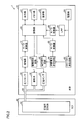
- FIG. 2 is a block diagram showing an outline of the configuration of the sphygmomanometer 1 in this embodiment.
- main body 10 includes control unit 20, memory unit 22, power supply unit 24, LPF (Low Pass Filter) 25, A / D in addition to display unit 21 and operation unit 23 described above.
- Converter 26, piezoelectric pump 31, exhaust valve 32, pressure sensor 33, DC-DC booster circuit 61, voltage control circuit 62, drive control circuit 63, current consumption measurement circuit 64, A / D A converter 65, an amplifier 71, and an A / D converter 72 are included.
- the piezoelectric pump 31 and the exhaust valve 32 correspond to a pressure increasing / decreasing mechanism for increasing / decreasing the internal pressure of the compression air bladder 42.
- the compression air bag 42 is for compressing the upper arm in the mounted state, and has a lumen inside thereof.
- the compression air bag 42 is connected to each of the piezoelectric pump 31, the exhaust valve 32, and the pressure sensor 33 described above via the air pipe 50 described above. Thereby, the compression air bag 42 is pressurized and expanded by driving the piezoelectric pump 31, and the internal pressure is maintained or reduced by controlling the driving of the exhaust valve 32 as a discharge valve. To do.
- the control unit 20 is configured by, for example, a CPU (Central Processing Unit), and is a part for controlling the entire blood pressure monitor 1.
- the control unit 20 may be a “control device”.
- the display unit 21 is composed of, for example, an LCD (Liquid Crystal Display) and is a part for displaying measurement results and the like.
- LCD Liquid Crystal Display
- the memory unit 22 is composed of, for example, a ROM (Read-Only Memory) or a RAM (Random-Access Memory), and stores a program for causing the control unit 20 or the like to execute a processing procedure for blood pressure value measurement or measurement. It is a part for memorizing results and the like.
- the operation unit 23 is a part for accepting an operation by a subject or the like and inputting a command from the outside to the control unit 20 or the power supply unit 24.
- the power supply unit 24 is a part for supplying electric power to each unit of the sphygmomanometer 1 such as the control unit 20 and the piezoelectric pump 31, and is a battery in this embodiment.
- the present invention is not limited to this, and the power source unit 24 may receive power from an external power source such as a commercial power source.
- the LPF 25 removes the high frequency component of the current from the power supply unit 24.
- the A / D converter 26 converts the voltage value of the current from the power supply unit 24 from which the high frequency component has been removed by the LPF 25 into a digital signal, and inputs the digital signal to the control unit 20.
- the control unit 20 inputs control signals for driving the piezoelectric pump 31 and the exhaust valve 32 to the voltage control circuit 62 and the drive control circuit 63, respectively, and displays blood pressure values as measurement results on the display unit 21 and the memory unit 22.
- type in The control unit 20 includes a blood pressure information acquisition unit (not shown) that acquires the blood pressure value of the subject based on the pressure value detected from the pressure sensor 33 via the amplifier 71 and the A / D converter 72.
- the blood pressure value acquired by the blood pressure information measuring unit is input to the display unit 21 and the memory unit 22 described above as a measurement result.
- the sphygmomanometer 1 may further include an output unit that outputs a blood pressure value as a measurement result to an external device such as a PC (Personal Computer) or a printer.
- an output unit for example, a serial communication line, a writing device for various recording media, or the like can be used.
- the DC-DC booster circuit 61 is a circuit that boosts the voltage of the battery serving as the power supply unit 24 to a voltage suitable for driving the piezoelectric pump 31.
- the voltage control circuit 62 controls the voltage supplied to the piezoelectric pump 31 based on the voltage value indicated by the control signal input from the control unit 20.
- the current consumption measuring circuit 64 measures the current value of the current consumed by the piezoelectric pump 31 via the voltage control circuit 62 and the drive control circuit 63.
- the A / D converter 65 converts the current value measured by the current consumption measuring circuit 64 into a digital signal and inputs the digital signal to the control unit 20.
- the drive control circuit 63 controls the piezoelectric pump 31 and the exhaust valve 32 based on the control signal input from the control unit 20. Specifically, the drive control circuit 63 controls the frequency of the current supplied to the piezoelectric pump 31 based on the control frequency indicated by the control signal input from the control unit 20. The drive control circuit 63 controls the opening / closing operation of the exhaust valve 32 based on the control signal input from the control unit 20.
- the piezoelectric pump 31 is for pressurizing the internal pressure (hereinafter also referred to as “cuff pressure”) of the compression air bag 42 by supplying air to the inner cavity of the compression air bag 42, and the operation thereof is described above.
- the drive control circuit 63 is controlled.
- the piezoelectric pump 31 discharges air with a predetermined flow rate by applying an alternating current with a predetermined drive frequency f0 and a predetermined amplitude V0.
- the alternating current may be a sinusoidal alternating current or a rectangular wave alternating current.
- the value of the peak-to-peak potential difference Vp-p may be used.
- the amplitude is half of the value of Vp-p. In the case of Vp-p, for example, the voltage value changes with a value from ⁇ Vp-p / 2 to Vp-p / 2.
- the exhaust valve 32 is for maintaining the internal pressure of the compression air bag 42 or opening the lumen of the compression air bag 42 to the outside to reduce the cuff pressure. It is controlled by the control circuit 63.
- the pressure sensor 33 detects the internal pressure of the compression air bladder 42 and inputs an output signal corresponding to the pressure to the amplifier 71.
- the amplifier 71 amplifies the level of the signal input from the pressure sensor 33.
- the A / D converter 72 converts the signal amplified by the amplifier 71 into a digital signal, and inputs the generated digital signal to the control unit 20.
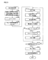
- FIG. 3 is a flowchart showing the blood pressure measurement process executed by the sphygmomanometer 1 according to the first embodiment.
- control unit 20 performs initialization. Specifically, the voltage value indicated by the calibration of the pressure sensor 33, the blockage of the exhaust valve 32, and the voltage control signal input to the voltage control circuit 62 is set to the minimum value V0.
- f0 is a specific frequency.
- the specific frequency is, for example, the upper limit frequency of the piezoelectric pump 31 or the driving frequency when the previous blood pressure measurement is completed.
- step S111 the control unit 20 adds 1 to t.
- step S112 a signal indicating the voltage value is transmitted to the voltage control circuit 62 and a signal indicating the drive frequency is transmitted to the drive control circuit 63 so as to drive the piezoelectric pump 31 with the voltage value V0 and the drive frequency f (k). Send.
- step S113 the control unit 20 is detected by the pressure sensor 33, and based on the change in the cuff pressure indicated by the signal input to the control unit 20 via the amplifier 71 and the A / D converter 72, The blood pressure value is calculated by a conventional method.
- step S114 the control unit 20 measures the current value I (t) based on the digital signal measured by the current consumption measurement circuit 64 and input to the control unit 20 via the A / D converter 65. To do.
- FIG. 4 is a graph showing the voltage value and current value of the current output from the DC-DC booster circuit 61.
- the voltage value of the current output from DC-DC boost circuit 61 takes a constant value obtained by boosting the voltage of the battery that is power supply unit 24.
- the current value of the current output from the DC-DC booster circuit 61 varies as shown in the graph according to the power consumption in the piezoelectric pump 31 connected to the subsequent stage of the circuit.
- FIG. 5 is a graph showing the voltage value and the current value of the current applied to the piezoelectric pump 31.
- the current boosted by DC-DC booster circuit 61 is converted into a predetermined voltage value and a predetermined frequency by voltage control circuit 62 and drive control circuit 63, as shown in the graph. , Voltage and current.
- the current value I (t) measured in step S114 is the peak value of the current described in FIG.
- step S115 the control unit 20 determines whether or not the previous current value I (t-1) is smaller than the current value I (t), that is, whether or not the current value has started to decrease. .
- the control unit 20 determines a predetermined value from the current drive frequency f (k). The value obtained by subtracting the value A is set as the next drive frequency f (k + 1).
- the predetermined value A is a frequency with the minimum resolution that can be controlled by the control unit 20, and is, for example, 50 Hz.
- step S117 the control unit 20 adds 1 to k. Then, the control part 20 returns the process to perform to the process of step S111.
- step S118 the control unit 20 determines whether or not the blood pressure measurement has been completed. If it is determined that the process has not been completed (NO in step S118), the control unit 20 returns the process to be executed to the process in step S111.
- step S121 the control unit 20 causes the voltage control circuit 62 and the drive control circuit to stop driving the piezoelectric pump 31. 63 is controlled.
- step S122 the control unit 20 controls the display unit 21 to display the blood pressure measurement result.
- step S118 the control unit 20 ends the blood pressure measurement process.
- step S115 As shown in FIG. 3, the drive frequency (control frequency) of the piezoelectric pump is obtained from the point at which the current consumption is maximized (that is, the point at which the impedance of the piezoelectric pump is minimized).
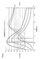
- FIG. 6 is a graph showing impedance characteristics and discharge pressure characteristics of the piezoelectric pump 31.
- the thin line indicates the impedance characteristic of the piezoelectric pump 31, and the thick line indicates the discharge pressure characteristic of the piezoelectric pump 31. Further, the voltage applied to the piezoelectric pump 31 differs for each line type.
- the piezoelectric pump has a relationship as shown in FIG.
- the impedance characteristic the higher the voltage to the piezoelectric pump, the lower the resonance frequency while lowering the impedance.
- the pressure characteristic the maximum pressure increases as the voltage increases, while the optimum frequency decreases.
- the frequency used as the maximum pressure at each voltage is near the resonance frequency. It is clear that no matter what voltage is applied, the peak of the maximum pressure exists near the impedance resonance point.
- the drive frequency at which the discharge pressure of the piezoelectric pump 31 is highest (hereinafter referred to as the optimum pressure frequency) is obtained from the point at which the current consumption is maximum (that is, the point at which the impedance of the piezoelectric pump 31 is minimum). is there.
- the determination unit sweeps the drive frequency from the initial control frequency in a direction in which the frequency decreases.
- step S116 the control unit 20 sets a value obtained by subtracting the predetermined value A from the current drive frequency f (k) as the next drive frequency f (k + 1). That is, when it is determined that the current value has started to decrease, the next drive frequency is swept from the current control frequency in a direction in which the frequency decreases.
- the frequency of the piezoelectric pump 31 when the drive frequency of the piezoelectric pump 31 according to the present embodiment is swept in an arbitrary frequency range from the upper limit frequency to the lower limit frequency of the frequency range in the direction of decreasing the frequency, the frequency The impedance characteristics of the piezoelectric pump 31 were compared with the case where the drive frequency was swept from the lower limit frequency to the upper limit frequency of the range in the direction of increasing the frequency.
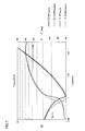
- FIG. 7 is a graph showing a comparison result of impedance characteristics of the piezoelectric pump 31.
- a thick line indicates a case where the drive frequency is swept in the direction of increasing the frequency
- a thin line indicates a case where the drive frequency is swept in the direction of decreasing the frequency.
- Impedance characteristics are shown on the left vertical axis, and phases are shown on the right vertical axis.
- a solid line indicates impedance characteristics.
- a broken line shows a phase.
- the optimum pressure frequency is obtained from the point at which the current consumption is maximized (that is, the point at which the impedance of the piezoelectric pump 31 is minimized).
- the amplitude of the piezoelectric pump 31 is maximized at the optimum pressure frequency.
- the piezoelectric pump 31 self-heats and is in a steady state (the piezoelectric pump is driven to some extent and the characteristics are stable). ) Frequency characteristics.
- the drive frequency when the drive frequency is swept in the direction of increasing the frequency, it does not pass through the optimum pressure frequency during the sweep, so that it is not driven in a steady state. Also, driving at such a frequency is not desirable because it may cause irregular vibrations near the point where the impedance is minimized.
- the determination unit preferably sweeps the drive frequency from the initial control frequency in a direction in which the frequency decreases.
- the blood pressure value can be measured at the drive frequency f (k) at which the current consumed by the piezoelectric pump 31 is maximized. For this reason, when pressurizing using the piezoelectric pump 31 in the pressurization process of the cuff pressure for blood pressure measurement, the piezoelectric pump 31 can be driven simply and efficiently.
- the determination unit uses the control frequency at the completion of the pressurization process as the control frequency at the start of the next pressurization process (that is, the specific frequency f0). In this way, when the sphygmomanometer 1 is used a plurality of times, the time required for blood pressure measurement processing can be further shortened.
- the determining unit includes a driving frequency determining unit that obtains the optimum driving frequency of the piezoelectric pump according to the voltage. By doing in this way, a piezoelectric pump can be driven simply and efficiently.
- the drive frequency is controlled so that the current consumed by the piezoelectric pump 31 is maximized while measuring the blood pressure value.
- the drive frequency at which the current consumed by the piezoelectric pump 31 is maximized is specified before blood pressure measurement is started.
- FIG. 8 is a flowchart showing the flow of blood pressure measurement processing executed by the sphygmomanometer 1 in the second embodiment.
- steps S131 to S133 are the same as steps S101 to S103 described with reference to FIG.
- step S141 the control unit 20 adds 1 to t.
- step S142 the control unit 20 transmits a signal indicating the voltage value to the voltage control circuit 62 and drives the drive control circuit 63 so as to drive the piezoelectric pump 31 with the voltage value V0 and the drive frequency f (k). A signal indicating the frequency is transmitted.
- step S144 the control unit 20 measures the current value I (t) based on the digital signal measured by the current consumption measurement circuit 64 and input to the control unit 20 via the A / D converter 65. To do. Similar to step S114 in FIG. 3, the current value I (t) measured in step S144 is the peak value of the current described in FIG.
- step S145 the control unit 20 determines whether or not the previous current value I (t-1) is smaller than the current value I (t), that is, whether or not the current value has started to decrease. . If it is determined that the current value has not decreased (ie, if YES is determined in step S145), that is, if it is determined that the current value has not started to decrease, in step S146, as in step S116 in FIG. A value obtained by subtracting the predetermined value A from the drive frequency f (k) is set as the next drive frequency f (k + 1).
- the predetermined value A is a frequency with the minimum resolution that can be controlled by the control unit 20, and is, for example, 50 Hz.
- step S 149 the control unit 20 determines whether f (k + 1) has reached the lower limit frequency of the piezoelectric pump 31. If it is determined that the lower limit frequency has not been reached (NO in step S149), the control unit 20 adds 1 to k in step S147. Then, the control part 20 returns the process to perform to the process of step S141.
- control unit 20 returns the process to be executed to the process of step S141.
- step S151 the control unit 20 stores f (t) as the specific frequency f0, The initial drive frequency f in the blood pressure measurement from now on is assumed to be f (t).
- step S152 the control unit 20 calculates a voltage V to be applied to the piezoelectric pump 31 for pressurizing the cuff 40 according to f (t).
- FIG. 9 is a graph showing the relationship between the applied voltage of the piezoelectric pump 31 and the drive frequency. Referring to FIG. 9, the relationship between the applied voltage of the piezoelectric pump and the drive frequency when the maximum flow rate is discharged at a certain pressure is substantially linear.
- the voltage V is calculated from the drive frequency f (t) in step S152 using the relationship described in FIG.
- step S153 the control unit 20 transmits a signal indicating a voltage value to the voltage control circuit 62 so as to drive the piezoelectric pump 31 with the voltage V and the driving frequency f calculated in step S152, and the drive control circuit.
- a signal indicating the drive frequency is transmitted to 63.
- step S154 the control unit 20 is detected by the pressure sensor 33, and based on the change in the cuff pressure indicated by the signal input to the control unit 20 via the amplifier 71 and the A / D converter 72, The blood pressure value is calculated by a conventional method.
- step S155 the control unit 20 determines whether the blood pressure measurement is completed. If it is determined that the blood pressure measurement is not completed (NO in step S155), the control unit 20 adds a predetermined value B to the voltage V applied to the piezoelectric pump 31 in step S156, and in step S157. Using the relationship described in FIG. 9 above, the process of calculating and executing the drive frequency f of the piezoelectric pump 31 for the equal pressure pressurization of the cuff 40 according to the voltage V added with B is executed in step S153. Return to processing.
- step S158 the control unit 20 causes the voltage control circuit 62 and the drive control circuit 63 to stop driving the piezoelectric pump 31. To control.
- step S159 the control unit 20 controls the display unit 21 to display the blood pressure measurement result. After step S159, the control unit 20 ends the blood pressure measurement process.
- the blood pressure value can be measured using the drive frequency f (k) that maximizes the current consumed by the piezoelectric pump 31 as the initial drive frequency. For this reason, the piezoelectric pump 31 can be driven simply and efficiently.
- the determination unit sweeps the drive frequency from the initial control frequency in a direction in which the frequency decreases. In this way, the same effect as the first embodiment can be obtained.
- the determining unit uses the control frequency at the completion of the pressurization process as the control frequency at the start of the next pressurization process (that is, the specific frequency f0). In this way, the same effect as the first embodiment can be obtained.
- the determination unit has a drive frequency determination unit that obtains the optimum drive frequency of the piezoelectric pump according to the voltage. In this way, the same effect as the first embodiment can be obtained.
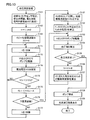
- the piezoelectric pump 31 is controlled based on the drive frequency at which the current consumed by the piezoelectric pump 31 is maximized. In the third embodiment, the piezoelectric pump 31 is controlled based on the drive frequency that maximizes the drop amount of the battery voltage.
- FIG. 10 is a flowchart showing the flow of blood pressure measurement processing executed by the sphygmomanometer 1 in the third embodiment.
- the processing from step S151 to step S159 is the same as the processing in FIG.
- the processing from step S161 to step S163, and step S171, step S172, step S176, step S179, and step S177 are the same as the processing from step S131 to step S133, and step S141, step S142, step S177 in FIG. It is the same as the process of S146, step S149, and step S147. For this reason, the overlapping description will not be repeated.
- step S ⁇ b> 144 the control unit 20 is measured by the current consumption measurement circuit 64 and based on the digital signal input to the control unit 20 via the A / D converter 65, the current value I (t ) Was measured.
- step S145 the control unit 20 determines whether or not the previous current value I (t-1) is smaller than the current value I (t).
- step S174 the control unit 20 is supplied from the power supply unit 24, the ripple noise that is a high-frequency component is removed by the LPF 25, and the voltage value converted into a digital signal by the A / D converter 26 is obtained. Based on this, the battery voltage V (t) is measured.
- step S175 the control unit 20 determines whether or not the previous battery voltage V (t-1) is greater than the current battery voltage V (t), that is, whether or not the battery voltage has started to increase. to decide.
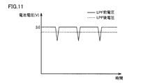
- FIG. 11 is a graph showing the battery voltage before and after the LPF 25.
- the voltage of the battery that is the power supply unit 24 before passing through the LPF 25 is supplied to the piezoelectric pump 31 via the DC-DC booster circuit 61, the voltage control circuit 62, and the drive control circuit 63 and consumed. Since the current that is generated is not constant, ripple noise is mixed. For this reason, as shown by the solid line in the graph of FIG.
- the battery voltage V (t) measured in step S174 is a voltage value indicated by a broken line in the graph described in FIG.
- step S175 When it is determined that the previous battery voltage V (t ⁇ 1) is greater than the current battery voltage V (t) (when YES is determined in step S175), that is, when it is determined that the battery voltage has not started to increase.
- step S176 processing similar to that in step S146 in FIG. 8 is executed.
- step S175 when it is determined that the previous battery voltage V (t ⁇ 1) is not greater than the current battery voltage V (t) (when NO is determined in step S175), that is, it is determined that the battery voltage has started to increase. In this case, the control unit 20 returns the process to be executed to the process of step S171.
- the blood pressure value is measured using the drive frequency f (k) that minimizes the battery voltage from the power supply unit 24 supplied to the piezoelectric pump 31 as the initial drive frequency. can do. For this reason, the piezoelectric pump 31 can be driven simply and efficiently.
- the determination unit sweeps the drive frequency from the initial control frequency in a direction in which the frequency decreases. In this way, the same effect as the first embodiment can be obtained.
- the determining unit uses the control frequency at the completion of the pressurization process as the control frequency at the start of the next pressurization process (that is, the specific frequency f0). In this way, the same effect as the first embodiment can be obtained.
- the determination unit has a drive frequency determination unit that obtains the optimum drive frequency of the piezoelectric pump according to the voltage. In this way, the same effect as the first embodiment can be obtained.
- the piezoelectric pump 31 is controlled based on the drive frequency at which the drop amount of the battery voltage supplied to the piezoelectric pump 31 is maximized.
- the drive frequency is swept to measure the battery voltage and the cuff pressure, and the piezoelectric pump 31 is controlled based on the drive frequency specified from the relationship between the battery voltage and the cuff pressure.
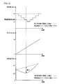
- FIG. 12 is a graph showing changes in power consumption when the drive frequency of the piezoelectric pump 31 is swept.
- the drive frequency of the piezoelectric pump 31 is decreased stepwise from 24 kHz, and when it reaches 23 kHz, it is swept by increasing stepwise. For example, it is increased or decreased in steps of 100 Hz.
- the cuff pressure controls the voltage applied to the piezoelectric pump 31 so as to be pressurized at a constant speed within a specified range from 0 to 30 mmHg.
- the piezoelectric pump 31 If the piezoelectric pump 31 is driven at the optimum driving frequency, which is the driving frequency at the time when the difference in power consumption between the case of driving at the same frequency and the case of driving by sweeping is maximized, the piezoelectric pump 31 discharges.
- the flow rate can be maximized.
- FIG. 13 is a graph showing the relationship between the cuff pressure and the battery voltage when the drive frequency of the piezoelectric pump is swept. Referring to FIG. 13, when the drive frequency is swept as shown in FIG. 12 and the cuff pressure and the battery voltage are plotted for each drive frequency, these plots are linear graphs when 24.0 kHz is not swept. Located at the lower left of.
- the drive frequency of the plot that is farthest from the straight line when not sweeping is equivalent to the optimum frequency described in FIG. That is, if the piezoelectric pump 31 is driven at the driving frequency, the flow rate discharged from the piezoelectric pump 31 can be maximized. This state is equivalent to the state where the current value consumed by the piezoelectric pump 31 is maximized and the state where the battery voltage value is minimized.
- FIG. 14 is a flowchart showing the flow of blood pressure measurement processing executed by the sphygmomanometer 1 in the fourth embodiment.
- the processing from step S151 to step S159 is the same as the processing of FIG. 8 and FIG.
- the process of step S181 is the same as step S131 of FIG. 8 and step S161 of FIG. For this reason, the overlapping description will not be repeated.
- f0 is a specific frequency.
- the specific frequency is, for example, the upper limit frequency of the piezoelectric pump 31 or the driving frequency when the previous blood pressure measurement is completed.
- step S184 the control unit 20 transmits a signal indicating the voltage value to the voltage control circuit 62 and sets the drive frequency to the drive control circuit 63 so as to drive the piezoelectric pump 31 with the voltage value V0 and the drive frequency f (k). Send the indicated signal.
- step S186 the control unit 20 is supplied from the power supply unit 24, the ripple noise that is a high frequency component is removed by the LPF 25, and the A / D converter 26 converts the digital signal into a digital signal.
- the battery voltage V (t) is measured, and the cuff pressure is measured based on a digital signal indicating the cuff pressure input from the pressure sensor 33 to the control unit 20 via the amplifier 71 and the A / D converter 72. .
- the control unit 20 stores the drive frequency at that time, the measured cuff pressure, and the battery voltage V (t) in the memory unit 22 in association with each other.
- step S187 the control unit 20 determines whether or not the drive frequency sweep has ended, that is, whether or not the drive frequency has been increased stepwise from 24 kHz to 23 kHz and then increased to 24 kHz. Judge whether or not.
- step S187 If it is determined that the sweep has not ended (NO in step S187), the control unit 20 adds 1 to k in step S188, and sets the next frequency of the sweep to f (k) in step S189. Then, the process to be executed is returned to the process of step S184.
- step S191 the control unit 20 stores the drive frequency, cuff pressure, and battery voltage V (t) stored in the memory unit 22. Based on the relationship, as described with reference to FIG. 13, the drive frequency of the plot of the cuff pressure and the battery voltage V (t) farthest from the straight line when not sweeping is specified as the optimum drive frequency f (t).
- the blood pressure value can be measured using the drive frequency f (k) specified based on the battery voltage supplied to the piezoelectric pump 31 as the initial drive frequency. For this reason, the piezoelectric pump 31 can be driven simply and efficiently.
- the sphygmomanometer 1 in the first to fourth embodiments exhibits the following effects.
- the sphygmomanometer 1 includes a cuff 40 that compresses the artery of the measurement site with the pressure of the internal fluid when attached to the blood pressure measurement site, a piezoelectric pump 31 that pressurizes the internal pressure of the cuff 40, and the cuff
- the exhaust valve 32 for reducing the pressure inside 40, the pressure sensor 33 for detecting the cuff pressure that is the pressure inside the cuff 40, and the control unit 20 are included.
- step S112 in FIG. 3 step S142 in FIG. 8, step S172 in FIG. 10, step S184 in FIG. 14, and step S153 in FIG. 8, FIG. 10, and FIG.
- the unit 20 controls to apply the determined amplitude and frequency to the piezoelectric pump.
- step S113 of FIG. 3 and step S154 of FIGS. 8, 10, and 14 the control unit 20 calculates a blood pressure value based on the cuff pressure detected by the pressure sensor 33.
- control unit 20 applies the amplitude of the predetermined voltage and the determined control frequency.
- the control unit 20 sets the control frequency when the voltage applied to the piezoelectric pump 31 is set to a predetermined voltage.
- the graph showing the relationship between the cuff pressure and the battery voltage detected by the pressure sensor 33 when changed, and the relationship between the acquired cuff pressure and the battery voltage, the cuff pressure and the battery when the control frequency is not changed The control frequency at a location where the distance is large with respect to the graph showing the relationship with the voltage is determined as the initial control frequency of the pressurizing process for pressurizing the pressure inside the cuff 40.
- control unit 20 changes the frequency when the voltage applied to the piezoelectric pump 31 is changed to a predetermined voltage.
- the control frequency at the minimum is determined as the initial control frequency of the pressurizing process for pressurizing the pressure inside the cuff 40.
- the sphygmomanometer 1 which is an example of the blood pressure measurement device determines the amplitude and frequency of the voltage to be applied to the piezoelectric pump 31, and is controlled to apply the determined amplitude and frequency to the piezoelectric pump 31.
- a blood pressure value is calculated based on the cuff pressure detected by the pressure sensor 33 which is an example of a detection unit.
- the amplitude of the predetermined voltage and the determined control frequency are applied to the piezoelectric pump 31.
- the relationship between the cuff pressure detected by the pressure sensor 33 and the battery voltage when the control frequency is changed when the voltage applied to the piezoelectric pump 31 is set to a predetermined voltage is acquired by the sphygmomanometer 1 and acquired.
- the control frequency at a location where the distance is larger than the graph showing the relationship between the cuff pressure and the battery voltage when the control frequency is not changed is It is determined as the initial control frequency of the pressurizing process for pressurizing the pressure.
- the voltage applied to the piezoelectric pump 31 is set to a predetermined voltage when a flow rate necessary for pressurizing the pressure inside the cuff 40 is supplied to the cuff 40. Then, the control frequency at which the consumption current flowing into the piezoelectric pump 31 is maximized is determined.
- the control frequency when the power supply voltage is minimized while changing the frequency increases the pressure in the cuff 40. Is determined as the initial control frequency.
- the piezoelectric pump 31 is driven so that the current consumption becomes maximum in the pressurizing process of the cuff 40 that compresses the measurement site.
- the piezoelectric pump 31 can be driven simply and efficiently during the pressurizing process of the cuff 40 that compresses the measurement site.
- steps S141 to S147 in FIG. 8 steps S171 to S177 in FIG. 10, and steps S184 to S189 in FIG. 20 determines the control frequency determined before the blood pressure value is calculated in step S154 as the initial control frequency of the pressurization process.
- control unit 20 specifies the control frequency f (t) of the current pressurization process at the start of determination of the next control frequency.
- the frequency is determined as f0.
- the drive frequency can be determined efficiently.
- step S116 and step S117 in FIG. 3 step S146 and step S147 in FIG. 8, and step S176 and step S177 in FIG. 10, the control unit 20 determines the frequency from the initial control frequency. The frequency is swept in the direction of lowering.
- control unit 20 uses the control frequency at the completion of the pressurization process as the control frequency at the start of the next pressurization process.
- the drive frequency can be determined efficiently.
- step S157 of FIG. 8, FIG. 10, and FIG. 14 the control unit 20 obtains the optimum drive frequency of the piezoelectric pump 31 according to the voltage.
- the cuff pressure that is the pressure inside the cuff 40 is equal to the discharge pressure of the piezoelectric pump 31.
- the fluid supplied from the piezoelectric pump 31 to the cuff 40 is air.
- the present invention is not limited to this, and the fluid supplied from the piezoelectric pump 31 to the cuff 40 may be another fluid, for example, a liquid.
- the invention has been described as the device of the sphygmomanometer 1.
- the present invention is not limited to this, and the invention can be understood as a method for controlling the sphygmomanometer 1.
- the invention can be understood as a control program for the sphygmomanometer 1.
Landscapes
- Health & Medical Sciences (AREA)
- Life Sciences & Earth Sciences (AREA)
- Vascular Medicine (AREA)
- Cardiology (AREA)
- Biomedical Technology (AREA)
- Heart & Thoracic Surgery (AREA)
- Physiology (AREA)
- Biophysics (AREA)
- Pathology (AREA)
- Engineering & Computer Science (AREA)
- Ophthalmology & Optometry (AREA)
- Physics & Mathematics (AREA)
- Medical Informatics (AREA)
- Molecular Biology (AREA)
- Surgery (AREA)
- Animal Behavior & Ethology (AREA)
- General Health & Medical Sciences (AREA)
- Public Health (AREA)
- Veterinary Medicine (AREA)
- Measuring Pulse, Heart Rate, Blood Pressure Or Blood Flow (AREA)
Applications Claiming Priority (2)
| Application Number | Priority Date | Filing Date | Title |
|---|---|---|---|
| JP2012095787A JP2013220321A (ja) | 2012-04-19 | 2012-04-19 | 血圧測定装置、血圧測定装置における制御装置、および、血圧測定装置の制御方法 |
| JP2012-095787 | 2012-04-19 |
Publications (1)
| Publication Number | Publication Date |
|---|---|
| WO2013157399A1 true WO2013157399A1 (fr) | 2013-10-24 |
Family
ID=49383363
Family Applications (1)
| Application Number | Title | Priority Date | Filing Date |
|---|---|---|---|
| PCT/JP2013/060317 Ceased WO2013157399A1 (fr) | 2012-04-19 | 2013-04-04 | Dispositif de mesure de la tension artérielle, dispositif de commande dans un dispositif de mesure de la tension artérielle et procédé de commande du dispositif de mesure de la tension artérielle |
Country Status (2)
| Country | Link |
|---|---|
| JP (1) | JP2013220321A (fr) |
| WO (1) | WO2013157399A1 (fr) |
Cited By (3)
| Publication number | Priority date | Publication date | Assignee | Title |
|---|---|---|---|---|
| JP2013220320A (ja) * | 2012-04-19 | 2013-10-28 | Omron Healthcare Co Ltd | 圧電ポンプ制御装置、圧電ポンプ制御方法、圧電ポンプ制御プログラム、および、血圧測定装置 |
| GB2575945A (en) * | 2019-11-11 | 2020-01-29 | Ttp Ventus Ltd | System for non-invasive blood pressure measurement |
| EP4112193A4 (fr) * | 2020-03-31 | 2024-04-03 | Minebea Mitsumi Inc. | Dispositif de commande de pompe et procédé de commande de pompe |
Families Citing this family (3)
| Publication number | Priority date | Publication date | Assignee | Title |
|---|---|---|---|---|
| JP5907322B1 (ja) | 2014-07-11 | 2016-04-26 | 株式会社村田製作所 | 吸引装置 |
| WO2017094276A1 (fr) | 2015-11-30 | 2017-06-08 | オムロンヘルスケア株式会社 | Élément de serrage souple et brassard de tensiomètre le comprenant |
| JP7597437B2 (ja) * | 2020-12-25 | 2024-12-10 | ミネベアミツミ株式会社 | ポンプシステム、流体供給装置および圧力検出方法 |
Citations (3)
| Publication number | Priority date | Publication date | Assignee | Title |
|---|---|---|---|---|
| JP2000171320A (ja) * | 1998-12-04 | 2000-06-23 | Matsushita Electric Works Ltd | 圧電ダイアフラムポンプの圧力測定方法及びその装置とこれを用いた血圧測定装置 |
| JP2007049890A (ja) * | 2005-08-08 | 2007-02-22 | Samsung Electro Mech Co Ltd | 周波数制御型ピエゾアクチュエーター駆動回路及び方法 |
| JP2009089504A (ja) * | 2007-09-28 | 2009-04-23 | Murata Mfg Co Ltd | 圧電素子の駆動電圧周波数調整機構およびそれを用いた圧電マイクロブロア |
-
2012
- 2012-04-19 JP JP2012095787A patent/JP2013220321A/ja active Pending
-
2013
- 2013-04-04 WO PCT/JP2013/060317 patent/WO2013157399A1/fr not_active Ceased
Patent Citations (3)
| Publication number | Priority date | Publication date | Assignee | Title |
|---|---|---|---|---|
| JP2000171320A (ja) * | 1998-12-04 | 2000-06-23 | Matsushita Electric Works Ltd | 圧電ダイアフラムポンプの圧力測定方法及びその装置とこれを用いた血圧測定装置 |
| JP2007049890A (ja) * | 2005-08-08 | 2007-02-22 | Samsung Electro Mech Co Ltd | 周波数制御型ピエゾアクチュエーター駆動回路及び方法 |
| JP2009089504A (ja) * | 2007-09-28 | 2009-04-23 | Murata Mfg Co Ltd | 圧電素子の駆動電圧周波数調整機構およびそれを用いた圧電マイクロブロア |
Cited By (5)
| Publication number | Priority date | Publication date | Assignee | Title |
|---|---|---|---|---|
| JP2013220320A (ja) * | 2012-04-19 | 2013-10-28 | Omron Healthcare Co Ltd | 圧電ポンプ制御装置、圧電ポンプ制御方法、圧電ポンプ制御プログラム、および、血圧測定装置 |
| GB2575945A (en) * | 2019-11-11 | 2020-01-29 | Ttp Ventus Ltd | System for non-invasive blood pressure measurement |
| GB2575945B (en) * | 2019-11-11 | 2023-02-08 | Ttp Ventus Ltd | System for non-invasive blood pressure measurement |
| EP4112193A4 (fr) * | 2020-03-31 | 2024-04-03 | Minebea Mitsumi Inc. | Dispositif de commande de pompe et procédé de commande de pompe |
| US12486838B2 (en) | 2020-03-31 | 2025-12-02 | Minebea Mitsumi Inc. | Pump control device and pump control system |
Also Published As
| Publication number | Publication date |
|---|---|
| JP2013220321A (ja) | 2013-10-28 |
Similar Documents
| Publication | Publication Date | Title |
|---|---|---|
| JP5998486B2 (ja) | 血圧測定装置、および、血圧測定装置の制御方法 | |
| JP5884496B2 (ja) | 血圧測定装置、および、血圧測定装置の制御方法 | |
| CN103841883B (zh) | 电子血压计 | |
| CN103284712B (zh) | 血压测定装置 | |
| CN103889320B (zh) | 电子血压计 | |
| US8808189B2 (en) | Blood pressure measurement device including cuff to be wrapped around measurement site | |
| CN102256539B (zh) | 电子血压计 | |
| RU2522969C2 (ru) | Электронный сфигмоманометр и способ измерения кровяного давления | |
| CN101969839B (zh) | 血压测定装置 | |
| JP2013220321A (ja) | 血圧測定装置、血圧測定装置における制御装置、および、血圧測定装置の制御方法 | |
| CN103025231B (zh) | 电子血压计 | |
| CN102036604A (zh) | 血压测定装置 | |
| JP2010051658A (ja) | 血圧情報測定装置 | |
| JP6136111B2 (ja) | 血圧測定装置 | |
| CN101528120A (zh) | 电子血压计 | |
| JP2014014556A (ja) | 電子血圧計および血圧測定方法 | |
| JP6035838B2 (ja) | 圧電ポンプ制御装置、圧電ポンプ制御方法、圧電ポンプ制御プログラム、および、血圧測定装置 | |
| JP2013090824A (ja) | 電子血圧計 | |
| JP2012115413A (ja) | 電子血圧計 | |
| JP2010035775A (ja) | 電子血圧計 |
Legal Events
| Date | Code | Title | Description |
|---|---|---|---|
| 121 | Ep: the epo has been informed by wipo that ep was designated in this application |
Ref document number: 13777899 Country of ref document: EP Kind code of ref document: A1 |
|
| DPE1 | Request for preliminary examination filed after expiration of 19th month from priority date (pct application filed from 20040101) | ||
| NENP | Non-entry into the national phase |
Ref country code: DE |
|
| 122 | Ep: pct application non-entry in european phase |
Ref document number: 13777899 Country of ref document: EP Kind code of ref document: A1 |