WO2013161415A1 - エンジン制御装置 - Google Patents
エンジン制御装置 Download PDFInfo
- Publication number
- WO2013161415A1 WO2013161415A1 PCT/JP2013/056897 JP2013056897W WO2013161415A1 WO 2013161415 A1 WO2013161415 A1 WO 2013161415A1 JP 2013056897 W JP2013056897 W JP 2013056897W WO 2013161415 A1 WO2013161415 A1 WO 2013161415A1
- Authority
- WO
- WIPO (PCT)
- Prior art keywords
- engine
- ion signal
- combustion
- cylinder temperature
- misfire
- Prior art date
- Legal status (The legal status is an assumption and is not a legal conclusion. Google has not performed a legal analysis and makes no representation as to the accuracy of the status listed.)
- Ceased
Links
Images






Classifications
-
- G—PHYSICS
- G01—MEASURING; TESTING
- G01L—MEASURING FORCE, STRESS, TORQUE, WORK, MECHANICAL POWER, MECHANICAL EFFICIENCY, OR FLUID PRESSURE
- G01L23/00—Devices or apparatus for measuring or indicating or recording rapid changes, such as oscillations, in the pressure of steam, gas, or liquid; Indicators for determining work or energy of steam, internal-combustion, or other fluid-pressure engines from the condition of the working fluid
- G01L23/22—Devices or apparatus for measuring or indicating or recording rapid changes, such as oscillations, in the pressure of steam, gas, or liquid; Indicators for determining work or energy of steam, internal-combustion, or other fluid-pressure engines from the condition of the working fluid for detecting or indicating knocks in internal-combustion engines; Units comprising pressure-sensitive members combined with ignitors for firing internal-combustion engines
- G01L23/221—Devices or apparatus for measuring or indicating or recording rapid changes, such as oscillations, in the pressure of steam, gas, or liquid; Indicators for determining work or energy of steam, internal-combustion, or other fluid-pressure engines from the condition of the working fluid for detecting or indicating knocks in internal-combustion engines; Units comprising pressure-sensitive members combined with ignitors for firing internal-combustion engines for detecting or indicating knocks in internal combustion engines
- G01L23/225—Devices or apparatus for measuring or indicating or recording rapid changes, such as oscillations, in the pressure of steam, gas, or liquid; Indicators for determining work or energy of steam, internal-combustion, or other fluid-pressure engines from the condition of the working fluid for detecting or indicating knocks in internal-combustion engines; Units comprising pressure-sensitive members combined with ignitors for firing internal-combustion engines for detecting or indicating knocks in internal combustion engines circuit arrangements therefor
-
- F—MECHANICAL ENGINEERING; LIGHTING; HEATING; WEAPONS; BLASTING
- F02—COMBUSTION ENGINES; HOT-GAS OR COMBUSTION-PRODUCT ENGINE PLANTS
- F02D—CONTROLLING COMBUSTION ENGINES
- F02D13/00—Controlling the engine output power by varying inlet or exhaust valve operating characteristics, e.g. timing
- F02D13/02—Controlling the engine output power by varying inlet or exhaust valve operating characteristics, e.g. timing during engine operation
-
- F—MECHANICAL ENGINEERING; LIGHTING; HEATING; WEAPONS; BLASTING
- F02—COMBUSTION ENGINES; HOT-GAS OR COMBUSTION-PRODUCT ENGINE PLANTS
- F02D—CONTROLLING COMBUSTION ENGINES
- F02D35/00—Controlling engines, dependent on conditions exterior or interior to engines, not otherwise provided for
- F02D35/02—Controlling engines, dependent on conditions exterior or interior to engines, not otherwise provided for on interior conditions
- F02D35/021—Controlling engines, dependent on conditions exterior or interior to engines, not otherwise provided for on interior conditions using an ionic current sensor
-
- F—MECHANICAL ENGINEERING; LIGHTING; HEATING; WEAPONS; BLASTING
- F02—COMBUSTION ENGINES; HOT-GAS OR COMBUSTION-PRODUCT ENGINE PLANTS
- F02D—CONTROLLING COMBUSTION ENGINES
- F02D35/00—Controlling engines, dependent on conditions exterior or interior to engines, not otherwise provided for
- F02D35/02—Controlling engines, dependent on conditions exterior or interior to engines, not otherwise provided for on interior conditions
- F02D35/025—Controlling engines, dependent on conditions exterior or interior to engines, not otherwise provided for on interior conditions by determining temperatures inside the cylinder, e.g. combustion temperatures
- F02D35/026—Controlling engines, dependent on conditions exterior or interior to engines, not otherwise provided for on interior conditions by determining temperatures inside the cylinder, e.g. combustion temperatures using an estimation
-
- F—MECHANICAL ENGINEERING; LIGHTING; HEATING; WEAPONS; BLASTING
- F02—COMBUSTION ENGINES; HOT-GAS OR COMBUSTION-PRODUCT ENGINE PLANTS
- F02D—CONTROLLING COMBUSTION ENGINES
- F02D35/00—Controlling engines, dependent on conditions exterior or interior to engines, not otherwise provided for
- F02D35/02—Controlling engines, dependent on conditions exterior or interior to engines, not otherwise provided for on interior conditions
- F02D35/027—Controlling engines, dependent on conditions exterior or interior to engines, not otherwise provided for on interior conditions using knock sensors
-
- F—MECHANICAL ENGINEERING; LIGHTING; HEATING; WEAPONS; BLASTING
- F02—COMBUSTION ENGINES; HOT-GAS OR COMBUSTION-PRODUCT ENGINE PLANTS
- F02P—IGNITION, OTHER THAN COMPRESSION IGNITION, FOR INTERNAL-COMBUSTION ENGINES; TESTING OF IGNITION TIMING IN COMPRESSION-IGNITION ENGINES
- F02P17/00—Testing of ignition installations, e.g. in combination with adjusting; Testing of ignition timing in compression-ignition engines
- F02P17/12—Testing characteristics of the spark, ignition voltage or current
-
- G—PHYSICS
- G01—MEASURING; TESTING
- G01M—TESTING STATIC OR DYNAMIC BALANCE OF MACHINES OR STRUCTURES; TESTING OF STRUCTURES OR APPARATUS, NOT OTHERWISE PROVIDED FOR
- G01M15/00—Testing of engines
- G01M15/04—Testing internal-combustion engines
- G01M15/10—Testing internal-combustion engines by monitoring exhaust gases or combustion flame
- G01M15/102—Testing internal-combustion engines by monitoring exhaust gases or combustion flame by monitoring exhaust gases
-
- F—MECHANICAL ENGINEERING; LIGHTING; HEATING; WEAPONS; BLASTING
- F02—COMBUSTION ENGINES; HOT-GAS OR COMBUSTION-PRODUCT ENGINE PLANTS
- F02D—CONTROLLING COMBUSTION ENGINES
- F02D2200/00—Input parameters for engine control
- F02D2200/02—Input parameters for engine control the parameters being related to the engine
- F02D2200/10—Parameters related to the engine output, e.g. engine torque or engine speed
- F02D2200/1015—Engines misfires
-
- F—MECHANICAL ENGINEERING; LIGHTING; HEATING; WEAPONS; BLASTING
- F02—COMBUSTION ENGINES; HOT-GAS OR COMBUSTION-PRODUCT ENGINE PLANTS
- F02D—CONTROLLING COMBUSTION ENGINES
- F02D35/00—Controlling engines, dependent on conditions exterior or interior to engines, not otherwise provided for
- F02D35/02—Controlling engines, dependent on conditions exterior or interior to engines, not otherwise provided for on interior conditions
- F02D35/028—Controlling engines, dependent on conditions exterior or interior to engines, not otherwise provided for on interior conditions by determining the combustion timing or phasing
-
- F—MECHANICAL ENGINEERING; LIGHTING; HEATING; WEAPONS; BLASTING
- F02—COMBUSTION ENGINES; HOT-GAS OR COMBUSTION-PRODUCT ENGINE PLANTS
- F02D—CONTROLLING COMBUSTION ENGINES
- F02D37/00—Non-electrical conjoint control of two or more functions of engines, not otherwise provided for
- F02D37/02—Non-electrical conjoint control of two or more functions of engines, not otherwise provided for one of the functions being ignition
-
- F—MECHANICAL ENGINEERING; LIGHTING; HEATING; WEAPONS; BLASTING
- F02—COMBUSTION ENGINES; HOT-GAS OR COMBUSTION-PRODUCT ENGINE PLANTS
- F02P—IGNITION, OTHER THAN COMPRESSION IGNITION, FOR INTERNAL-COMBUSTION ENGINES; TESTING OF IGNITION TIMING IN COMPRESSION-IGNITION ENGINES
- F02P17/00—Testing of ignition installations, e.g. in combination with adjusting; Testing of ignition timing in compression-ignition engines
- F02P17/12—Testing characteristics of the spark, ignition voltage or current
- F02P2017/125—Measuring ionisation of combustion gas, e.g. by using ignition circuits
-
- Y—GENERAL TAGGING OF NEW TECHNOLOGICAL DEVELOPMENTS; GENERAL TAGGING OF CROSS-SECTIONAL TECHNOLOGIES SPANNING OVER SEVERAL SECTIONS OF THE IPC; TECHNICAL SUBJECTS COVERED BY FORMER USPC CROSS-REFERENCE ART COLLECTIONS [XRACs] AND DIGESTS
- Y02—TECHNOLOGIES OR APPLICATIONS FOR MITIGATION OR ADAPTATION AGAINST CLIMATE CHANGE
- Y02T—CLIMATE CHANGE MITIGATION TECHNOLOGIES RELATED TO TRANSPORTATION
- Y02T10/00—Road transport of goods or passengers
- Y02T10/10—Internal combustion engine [ICE] based vehicles
- Y02T10/12—Improving ICE efficiencies
Definitions
- the present invention relates to an engine control device, and more particularly to an abnormal combustion detection device using an ion signal.
- the average value of ion signals for the past several cycles is set as the background level, and a method of calculating the determination threshold based on the background level is taken, but when the engine load or the rotation speed changes, There is a problem that a certain delay occurs in the change of the determination threshold value.
- an ionic current value (background) at the time of normal combustion is stored on an engine operation map with the engine load and the rotational speed as axes, and a knock determination threshold value is set based on the value.
- a method of correcting and updating the determination threshold value for each driving region by learning is known.
- the in-cylinder state (gas composition or temperature) deviates transiently from steady operating conditions centered on the engine load and speed. ).
- the actual value of the EGR rate is overshoot or undershoot with respect to the target value.
- an in-cylinder state gas composition and gas temperature
- abnormal combustion is erroneously determined as abnormal combustion (knock, misfire).
- abnormal combustion knock, misfire
- an object of the present invention is to control an engine that can accurately determine knocking or misfire under any operating condition, including a transient condition in which the in-cylinder state rapidly changes.
- the engine control apparatus of the present invention comprises an ion signal detection means for detecting ions generated during combustion, and an abnormality for determining knock or misfire based on the ion signal detected by the detection means.
- An engine control device comprising a combustion determination means, comprising: an in-cylinder temperature estimating means for estimating an in-cylinder temperature of a normal combustion cycle under the current operating condition of the engine, and knocking an ion signal based on the estimated in-cylinder temperature information It is characterized by setting a judgment threshold value or a misfire judgment threshold value.
- in-cylinder temperature information correlated with the ion signal value is estimated for each cycle, and a determination threshold value is set based on the temperature information, thereby suppressing erroneous determination under any operating condition and causing abnormalities. It becomes possible to improve the detection accuracy of combustion.
- the in-cylinder temperature estimation means is configured to open and close an intake valve and an exhaust valve that control pressure inside the intake pipe of the engine and intake and exhaust of the engine.
- In-cylinder temperature is estimated using at least one of a timing, an air-fuel ratio that is a mass ratio of air and fuel supplied to the combustion chamber of the engine, and an ignition signal for controlling the ignition timing of the engine It is characterized by.
- in-cylinder temperature estimation allows more accurate in-cylinder temperature estimation by taking into account engine control parameter values that directly affect the in-cylinder temperature such as the intake / exhaust valve, air-fuel ratio, and ignition timing. .
- the abnormal combustion determination means is based on an integral value of an ion signal for a predetermined period in a combustion cycle or a peak value of an ion signal within a predetermined period. It is characterized by determining knock or misfire.
- the abnormal combustion determination means determines that the engine is knocking or misfiring, of the ignition timing of the engine and the closing timing of the intake valve, It is characterized by changing at least one.
- the engine control device further includes a steady operation determination unit that determines whether the current engine operation state is a steady operation state, and the steady operation determination unit determines that the operation is not steady operation.
- a knock determination threshold value or a misfire determination threshold value of the ion signal is set based on the in-cylinder temperature information.
- in-cylinder temperature estimation is performed because abnormal combustion determination based on the estimated in-cylinder temperature information is performed only under conditions that are determined not to be steady conditions, that is, transient conditions in which the behavior of in-cylinder gas changes significantly. Therefore, it is possible to minimize the increase in the calculation load on the ECU.
- the present invention even in a transient condition in which the in-cylinder state changes rapidly, by setting the abnormal combustion determination threshold value of the ionic current based on the estimated in-cylinder temperature information, knocking and misfire can be accurately performed. Thus, abnormal combustion can be minimized.
- the system block diagram of the control apparatus of the engine by the 1st Embodiment of this invention The ignition system block diagram of the control apparatus of the engine by the 1st Embodiment of this invention.
- Explanatory drawing of the knock detection principle of the abnormal combustion determination method of the control apparatus of the engine by the 1st Embodiment of this invention Explanatory drawing of the knock detection principle of the abnormal combustion determination method of the control apparatus of the engine by the 1st Embodiment of this invention.
- the system block diagram which shows the structure of the control apparatus of the engine by the 1st Embodiment of this invention.
- 1 is a schematic diagram of abnormal combustion determination and avoidance control logic that is performed in an ECU of an engine control apparatus according to a first embodiment of the present invention.
- the flowchart which shows the abnormal combustion determination by the ion signal of the engine control apparatus by the 1st Embodiment of this invention, and the avoidance control content.
- the system block diagram of the control apparatus of the engine by the 2nd Embodiment of this invention The representative example of the ignition signal and ion signal of the control apparatus of the engine by the 2nd Embodiment of this invention.
- the system block diagram which shows the structure of the control apparatus of the engine by the 2nd Embodiment of this invention.
- the schematic diagram of the abnormal combustion determination and avoidance control logic implemented within ECU of the control apparatus of the engine by the 2nd Embodiment of this invention.
- the flowchart which shows the abnormal combustion determination and the avoidance control content by the ion signal of the control apparatus of the engine by the 2nd Embodiment of this invention.
- the flowchart which shows the abnormal combustion determination and the avoidance control content by the ion signal of the control apparatus of the engine by the 3rd Embodiment of this invention.
- FIG. 1 is a system configuration diagram showing the configuration of a system in which an engine control apparatus according to a first embodiment of the present invention is applied to an in-cylinder gasoline injection engine for automobiles.
- Engine 100 is a four-cylinder gasoline engine for automobiles that performs spark ignition combustion.
- An airflow sensor 1 that measures the amount of intake air
- an electronic control throttle 2 that adjusts the intake pipe pressure
- an intake air temperature sensor 15 that is an aspect of the intake air temperature detector and measures the temperature of intake air
- An intake pressure sensor 21 for measuring the pressure in the pipe is provided at an appropriate position of each intake pipe 6.
- the engine 100 is provided with a fuel injection device (hereinafter referred to as an injector 3) for injecting fuel into the combustion chamber 12 of each cylinder and an ignition system 4 for supplying ignition energy for each cylinder.
- a cooling water temperature sensor 14 for measuring the temperature of the cylinder head 7 is provided at an appropriate position.
- Each of the cylinder heads 7 includes a variable valve 5 including an intake valve variable device 5a for adjusting the intake gas flowing into the cylinder and an exhaust valve variable device 5b for adjusting the exhaust gas discharged from the cylinder.
- a variable valve 5 including an intake valve variable device 5a for adjusting the intake gas flowing into the cylinder and an exhaust valve variable device 5b for adjusting the exhaust gas discharged from the cylinder.
- a high-pressure fuel pump 17 for supplying high-pressure fuel to the injector 3 is connected to the injector 3 by a fuel pipe.
- a fuel pressure sensor 18 for measuring the fuel injection pressure is provided in the fuel pipe.
- a three-way catalyst 10 for purifying exhaust and an air-fuel ratio detector, an air-fuel ratio sensor 9 for detecting the air-fuel ratio of the exhaust on the upstream side of the three-way catalyst 10, and an exhaust temperature detector
- an exhaust temperature sensor 11 that measures the temperature of the exhaust gas upstream of the three-way catalyst 10 is provided at each appropriate position of the exhaust pipe 8.
- the crankshaft is provided with a crank angle sensor 13 for calculating the rotation angle.
- a signal obtained from the variable valve 5 (phase angle sensor) is sent to an engine control unit (ECU) 20. Further, a signal obtained from the accelerator opening sensor 16 is sent to the ECU 20.
- the accelerator opening sensor 16 detects the amount of depression of the accelerator pedal, that is, the accelerator opening.
- the ECU 20 calculates the required torque based on the output signal of the accelerator opening sensor 16. That is, the accelerator opening sensor 16 is used as a required torque detection sensor that detects a required torque for the engine.
- the ECU 20 calculates the rotational speed of the engine based on the output signal of the crank angle sensor 13.
- the ECU 20 optimally calculates main operating amounts of the engine such as the air flow rate, the fuel injection amount, the ignition timing, and the fuel pressure based on the operating state of the engine obtained from the outputs of the various sensors.
- the fuel injection amount calculated by the ECU 20 is converted into a valve opening pulse signal and sent to the injector 3. Further, an ignition signal 4h is sent to the ignition system 4 so as to be ignited at the ignition timing calculated by the ECU 20.
- the throttle opening calculated by the ECU 20 is sent to the electronic control throttle 2 as a throttle drive signal. Further, the operation amount of the variable valve calculated by the ECU 20 is sent to the variable valve 5 as a variable valve drive signal.
- the fuel pressure calculated by the ECU 20 is sent to the high pressure fuel pump 17 as a high pressure fuel pump drive signal.
- Fuel is injected from the intake pipe 6 through the intake valve into the combustion chamber 12 to form an air-fuel mixture.
- the air-fuel mixture explodes by a spark generated from the spark plug 4a at a predetermined ignition timing, and the piston is pushed down by the combustion pressure to become the driving force of the engine. Further, the exhaust gas after the explosion is sent to the three-way catalyst 10 through the exhaust pipe 8, and the exhaust components are purified in the three-way catalyst 10 and discharged to the outside.
- FIG. 2 is a diagram showing a configuration of the ignition system 4 of the engine control apparatus according to the first embodiment of the present invention.
- a current flows through the primary ignition coil 4c via the igniter 4i.
- an electromotive force is generated in the secondary ignition coil 4b, a high voltage is applied to the tip of the spark plug 4a, and spark discharge occurs.
- spark discharge current flows in the direction of arrow I in the figure.
- the voltage of the secondary ignition coil 4b decreases and becomes lower than the breakdown voltage (for example, 100V) of the Zener diode 4e, the current flows into the capacitor 4d, and the capacitor 4d is charged.
- the breakdown voltage for example, 100V
- the spark discharge creates a flame kernel in the gap between the spark plugs, and then the flame propagates into the combustion chamber.
- ions such as chemical ions and thermal ions exist as intermediate products in the combustion process.
- a voltage in this case, 100 V
- ions are generated in the circuit.
- Current flows (direction II in the figure). This ionic current is voltage-converted by the voltage conversion resistor 4f and then sent to the ECU 20 as an ion signal 4g.
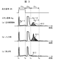
- FIG. 3 is a diagram showing representative examples of an ignition signal and an ion signal in the engine control apparatus according to the first embodiment of the present invention.
- the ion signal is characterized by three peaks.
- the first peak 4g-1 is a waveform that is seen when the ion signal detection circuit is built in the ignition system 4.
- a current flows through the ion signal detection unit and the ion flows.
- Output as a signal. In practice, this is treated as noise because there is no combustion flame in the combustion chamber.
- the second peak 4g-2 is a waveform that is seen after the ignition signal 4h is cut off at time t2 after the charging time ⁇ ta and a spark flies between the gaps of the spark plug 4a. Although the ion signal cannot be detected, the ion component in the initial combustion flame is subsequently detected.
- the third peak 4g-3 is a waveform that is detected when the combustion flame burns and spreads throughout the combustion chamber. It matches the pressure waveform in the combustion chamber and detects the ionic components in the flame of the main combustion portion. Yes.
- the integrated value of the signal at the third peak is used for determining abnormal combustion.
- the ignition signal 4h is interrupted at time t2, and the ion signal 4g from time t3 after the passage of ⁇ tb to time t4 after the passage of ⁇ tc is integrated. This is S (i).
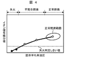
- FIG. 4 is an explanatory diagram of the misfire detection principle of the abnormal combustion determination method in the engine control apparatus according to the first embodiment of the present invention.
- the horizontal axis of the graph represents a value corresponding to the indicated mean effective pressure, that is, the engine torque, and the vertical axis represents the ion signal integrated value.
- the combustion state is stable, it is within the normal combustion range in the figure.
- the ion signal integrated value S (i) becomes small, and it can be determined that misfire occurs when the value falls below the set misfire determination threshold value.
- the black plot is a condition for determining a misfire. As described above, since the ion signal during normal combustion changes depending on operating conditions such as the engine speed, it is necessary to change the misfire determination threshold value depending on the operating conditions.
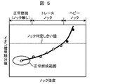
- FIG. 5 is an explanatory diagram of the knock detection principle of the abnormal combustion determination method in the engine control apparatus according to the first embodiment of the present invention.
- the horizontal axis of the graph is the knock intensity, for example, a value obtained by calculating the vibration intensity of the knock frequency component from the output signal of the knock sensor, and the vertical axis is the ion signal integrated value.
- the further to the left, the larger the knock strength, and the leftmost portion is a heavy knock state.
- knock does not occur, it is within the normal combustion range in the figure.
- the pressure / temperature in the combustion chamber rises and the ion signal integrated value S (i) increases.
- a knock can be determined when the set knock determination threshold is exceeded.
- Black plots in the figure are conditions for determining knocking. As described above, since the ion signal during normal combustion changes depending on operating conditions such as the engine speed, it is necessary to change the knock determination threshold value depending on the operating conditions.
- FIG. 6 is a diagram showing the relationship between the integrated value of the ion signal and the maximum temperature in the cylinder.
- the results obtained by changing various parameters such as engine load, engine speed, air-fuel ratio, EGR rate, etc. are plotted. From this figure, it is understood that the ion signal has a strong correlation with the maximum temperature in the cylinder, and the ion signal increases as the maximum temperature in the cylinder increases. For example, the deepest in-cylinder temperature rises under conditions where the engine load is large, so that the ion signal integrated value also increases. In addition, under a condition where the EGR rate is large, the heat capacity of the in-cylinder gas increases, so that the in-cylinder maximum temperature decreases and the ion signal integrated value decreases.
- the misfire and knock detection principles shown in FIGS. 4 and 5 also utilize the relationship between the in-cylinder maximum temperature and the ion signal.
- the engine control apparatus in the present embodiment predicts the maximum in-cylinder temperature during normal combustion in the target cycle, and calculates the ion signal during normal combustion using the relationship shown in FIG. Thereafter, an abnormal combustion determination threshold is calculated from the ion signal during normal combustion. For example, a value obtained by multiplying a signal during normal combustion by a constant is set as an abnormal combustion determination threshold value.
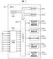
- FIG. 7 is a system block diagram showing the configuration of the engine control apparatus according to the first embodiment of the present invention.
- Airflow sensor 1, ion signal 4g, air-fuel ratio sensor 9, exhaust temperature sensor 11, crank angle sensor 13, cooling water temperature sensor 14, intake air temperature sensor 15, accelerator opening sensor 16, fuel pressure sensor 18, intake air pressure sensor 21, Is input to the input circuit 20a of the ECU 20.
- the input signal is not limited to these.
- the input signal of each input sensor is sent to the input port in the input / output port 20b.
- the value sent to the input / output port 20b is stored in the RAM 20c and processed by the CPU 20e.
- a control program describing the contents of the arithmetic processing is written in advance in the ROM 20d.
- the value indicating the operation amount of each actuator calculated in accordance with the control program is stored in the RAM 20c, then sent to the output port in the input / output port 20b, and sent to each actuator via each drive circuit.
- Each circuit controls the electronic control throttle 2, the injector 3, the ignition system 4, the variable valve 5, and the high-pressure fuel pump 17, respectively.
- the device includes the drive circuit in the ECU 20.
- the present invention is not limited to this, and any of the drive circuits may be provided in the ECU 20.
- ECU20 determines abnormal combustion based on an input signal, and when it determines with it being abnormal combustion, it controls ignition timing and a variable valve.
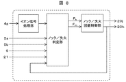
- FIG. 8 is a diagram showing an outline of the abnormal combustion determination and avoidance control logic executed in the ECU 20 of the engine control apparatus according to the first embodiment of the present invention. It comprises an ion signal processing unit, a knock / misfire determination unit, and a knock / misfire avoidance control unit.
- the ion signal 4g is input to the ion signal processing unit, and integration processing in a predetermined section is executed as shown in FIG.
- the knock / misfire determination unit includes the variable valve 5 to the current valve phase (especially the intake valve closing timing and the exhaust valve closing timing), the air-fuel ratio, the intake pipe pressure, and the ignition signal (ignition timing). Is entered.
- the maximum in-cylinder temperature during normal combustion is estimated based on the intake valve closing timing, the exhaust valve closing timing, the air-fuel ratio, the intake pipe pressure, and the ignition timing. Specifically, the in-cylinder air amount and the internal EGR amount are obtained from the exhaust valve closing timing and the intake pipe pressure.
- the in-cylinder temperature history of the air cycle in the compression / expansion stroke is obtained from the effective compression ratio obtained from the intake valve closing timing, the in-cylinder air amount, and the internal EGR amount. It is possible to estimate the maximum in-cylinder temperature during normal combustion based on the in-cylinder temperature history of this air cycle, the amount of heat generated during combustion obtained from the air-fuel ratio, and the combustion end timing that can be estimated from the ignition timing. it can.
- the ion signal integral value at the time of normal combustion is calculated using the relationship shown in FIG. 6, and the determination threshold value for knocking and misfire is calculated by multiplying it by a constant.
- Knock and misfire are determined by comparing the threshold value for determining knock and misfire with the input ion integration value. If it is determined that knocking 1 knock determination flag F k, is set to 1 misfire determination flag F m If it is determined that a misfire, and outputs the knock / misfire avoidance control section.
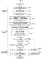
- FIG. 9 is a flowchart showing abnormal combustion determination and avoidance control contents based on ion signals in the engine control apparatus according to the first embodiment of the present invention.
- the control content shown in FIG. 9 is repeatedly executed by the ECU 20 at a predetermined cycle.
- step S901 the ECU 20 reads the ion signal 4g.
- step S902 a period for integrating the ion signal is set. Basically, the integration period is set from the elapse of a certain time (for example, 2 ms) from the ignition timing to the timing (for example, 90 deg. ATDC) at which combustion ends. This integration period is stored in advance as a map for each operating condition.
- step S903 an ion signal integrated value S (i) is calculated.
- the symbol i means the i-th cycle.
- the maximum in-cylinder temperature T max during normal combustion is calculated.
- the normal combustion ion signal integration value S b (i) is calculated from the maximum in-cylinder temperature T max during normal combustion.
- the ECU 20 stores in advance a formula (approximate formula) of the relationship between the maximum in-cylinder temperature and the ion signal shown in FIG. 6, and the calculation is performed using the formula.
- a knock determination threshold value S k (i) and a misfire determination threshold value S m (i) are calculated from the normal combustion ion signal integrated value S b (i). For example, a value obtained by multiplying a normal combustion ion signal integrated value S b (i) by a constant A, a knock determination threshold value S k (i), and a normal combustion ion signal integrated value S b (i) by a constant B.
- the multiplied value is defined as a misfire determination threshold value S m (i).
- A is set to about 1.2 to 2.0
- B is set to about 0.1 to 0.5.
- step S908 the ion signal integrated value S (i) and the knock determination threshold value S k (i) are compared to determine whether or not the knock is made. If S (i)> S k (i), it is determined that knocking has occurred, and the process proceeds to step S909. If S (i) ⁇ S k (i), it is determined that it is not knocking, and the process proceeds to step S911. In step S909, retard control of the ignition timing is performed in order to avoid knock, and in step S910, retard control of the intake valve close timing (decrease in the effective compression ratio) is performed in order to avoid knock. Then, a series of control is finished.
- step S911 by comparing the ion signal integral value S (i) and flameout determination threshold S m (i), determines whether or not misfire. If S (i) ⁇ S m (i), it is determined that there is no misfire, and the series of controls is terminated. If S (i) ⁇ S m (i), it is determined that a misfire has occurred, and the process proceeds to step S912. In step S912, ignition timing advance control is performed to avoid misfire, and in step S913, intake valve close timing advance control (increase in effective compression ratio) is performed to avoid misfire. Then, a series of control is finished.
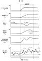
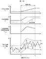
- FIG. 10 shows a time chart of the abnormal combustion determination by the ion signal by the engine control apparatus according to the first embodiment of the present invention. From the top in the figure, accelerator opening ⁇ , intake pipe pressure P in , air-fuel ratio A / F, intake valve closing timing ⁇ ivc , maximum in-cylinder temperature during normal combustion (estimated value) T max , ion signal integrated value S The time change of is shown. In the chart of the ion signal integrated value S, the normal combustion ion signal integrated value S b , the knock determination threshold value S k , and the misfire determination threshold value S m are also shown. In this example, it is assumed that no knock or misfire has occurred.
- an operation with a constant accelerator opening is performed, and the engine operating state (intake pipe pressure, air-fuel ratio, etc.) and the estimated maximum in-cylinder temperature during normal combustion are stable.
- the accelerator is depressed by the driver, first throttle is opened by receiving it, an intake pipe pressure starts rising.
- the intake pipe pressure rises with a certain time delay from the accelerator opening.
- the fuel injection amount is controlled so as to obtain a desired air-fuel ratio (for example, stoichiometric ratio) in accordance with the amount of air in the cylinder.
- the air-fuel ratio is In some cases, it may become temporarily rich.
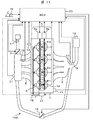
- FIG. 11 is a system configuration diagram showing a system configuration in which the engine control apparatus according to the second embodiment of the present invention is applied to an in-cylinder gasoline injection engine for automobiles.
- a bypass passage between the exhaust pipe and the intake pipe is provided, and the exhaust amount flowing into the intake pipe is controlled in the passage.
- An EGR valve 19 is provided.
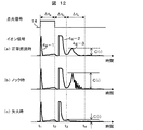
- FIG. 12 is a diagram showing a representative example of an ignition signal and an ion signal in the engine control apparatus according to the second embodiment of the present invention.
- the ion signals during normal combustion, knocking, and misfire are as shown in FIG.
- the pressure / temperature in the combustion chamber rises with the occurrence of knocking, so that the third peak signal becomes large, and a vibration component having a knocking frequency is on it.
- the peak value of the third peak signal is used for abnormal combustion determination in the present embodiment.
- the ignition signal 4h is cut off at time t2, and the peak value of the ion signal 4g from time t3 after the passage of ⁇ tb to time t4 after the passage of ⁇ tc is calculated. This is C (i).
- the determination principle of knocking and misfire using the ion signal in the present embodiment is the same as that described in FIGS. 4 to 6 (the ion signal integrated value may be replaced with the ion signal peak value).
- FIG. 13 is a system block diagram showing the configuration of the engine control apparatus according to the second embodiment of the present invention.
- the opening degree of the EGR valve 19 as an input signal and an EGR valve drive circuit 20l are provided. Is a feature.
- FIG. 14 is a diagram showing an outline of the abnormal combustion determination and avoidance control logic executed in the ECU 20 of the engine control apparatus according to the second embodiment of the present invention.
- the knock / misfire determination unit includes an EGR valve as an input signal.
- the calculation content in the ion signal processing unit is different from that in the first embodiment.
- the ion signal 4g is input to the ion signal processing unit, and the peak value of the ion signal in a predetermined section is output as shown in FIG.
- the knock / misfire determination unit starts from the variable valve 5 to the current valve phase (especially the intake valve closing timing and exhaust valve closing timing), the air-fuel ratio, the intake pipe pressure, and the ignition signal (ignition timing).
- EGR valve opening is input.
- the maximum in-cylinder temperature during normal combustion is estimated based on the intake valve closing timing, exhaust valve closing timing, air-fuel ratio, intake pipe pressure, ignition timing, and EGR valve opening.
- the in-cylinder air amount and the internal EGR amount are obtained from the exhaust valve closing timing, the intake pipe pressure, and the EGR valve opening.
- the in-cylinder temperature history of the air cycle in the compression / expansion stroke is obtained from the effective compression ratio obtained from the intake valve closing timing, the in-cylinder air amount, and the internal EGR amount. It is possible to estimate the maximum in-cylinder temperature during normal combustion based on the in-cylinder temperature history of this air cycle, the amount of heat generated during combustion obtained from the air-fuel ratio, and the combustion end timing that can be estimated from the ignition timing. it can. Based on the estimated maximum in-cylinder temperature at the time of normal combustion, the ion signal integral value at the time of normal combustion is calculated using the relationship shown in FIG.
- Knock and misfire are determined by comparing the threshold value for determining knock and misfire with the input ion integration value. If it is determined that knocking 1 knock determination flag F k, is set to 1 misfire determination flag F m If it is determined that a misfire, and outputs the knock / misfire avoidance control section.
- the knock / misfire avoidance control unit is the same as in the first embodiment.
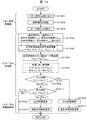
- FIG. 15 is a flowchart showing abnormal combustion determination and avoidance control contents based on ion signals in the engine control apparatus according to the second embodiment of the present invention.
- the control content shown in FIG. 15 is repeatedly executed by the ECU 20 at a predetermined cycle.
- step S1501 the ECU 20 reads the ion signal 4g.
- step S1502 an ion signal calculation period is set. Basically, the calculation period is set from the elapse of a certain time (for example, 2 ms) from the ignition timing to the timing (for example, 90 deg. ATDC) at which combustion ends. This calculation period is stored in advance as a map for each operating condition.
- step S1503 an ion signal peak value C (i) is calculated.
- the symbol i means the i-th cycle.
- step S1507 it calculates a knock determination threshold value C k (i) and flameout determination threshold C m (i) from the normal combustion ion signal peak value C b (i).
- the normal combustion ion signal integrated value C b (i) multiplied by the constant A is set to the knock determination threshold C k (i)
- the normal combustion ion signal integrated value C b (i) is set to the constant B.
- the multiplied value is defined as a misfire determination threshold value C m (i).
- A is set to about 1.2 to 2.0
- B is set to about 0.1 to 0.5.
- step S1508 the ion signal peak value C (i) is compared with the knock determination threshold value C k (i) to determine whether or not it is a knock. If C (i)> C k (i), it is determined that knocking has occurred, and the process proceeds to step S1509. If C (i) ⁇ C k (i), it is determined that it is not knocking, and the process proceeds to step S1511. In step S1509, ignition timing retardation control is performed to avoid knocking, and in step S1510, intake valve closing timing retardation control (decrease in the effective compression ratio) is performed to avoid knocking. Then, a series of control is finished.
- step S1508 If it is determined in step S1508 that the engine is not knocked, the process proceeds to step S1511, and the ion signal peak value C (i) is compared with the misfire determination threshold value C m (i) to determine whether misfire has occurred. If C (i) ⁇ C m (i), it is determined that there is no misfire, and the series of controls is terminated. If C (i) ⁇ C m (i), it is determined that a misfire has occurred, and the process proceeds to step S1512. In step S1512, ignition timing advance control is performed in order to avoid misfire, and in step S1513, intake valve close timing advance control (increase in effective compression ratio) is performed in order to avoid misfire. Then, a series of control is finished.
- FIG. 16 shows a time chart of the abnormal combustion determination by the ion signal by the engine control apparatus according to the second embodiment of the present invention. From the top of the figure, accelerator opening ⁇ , intake pipe pressure P in , air-fuel ratio A / F, intake valve closing timing ⁇ ivc , EGR valve opening ⁇ , maximum in-cylinder temperature during normal combustion (estimated value) T max The time change of the ion signal peak value C is shown. In the chart of the ion signal peak value C, the normal combustion ion signal integrated value C b , the knock determination threshold value C k , and the misfire determination threshold value C m are also shown. In this example, it is assumed that no knock or misfire has occurred.
- the knock / misfire determination threshold value C k is C m is calculated. Since the measured ion signal integrated value C is within the range of C k ⁇ C ⁇ C m within the illustrated period, it is determined that there is no knock / misfire.
- the abnormal combustion judgment threshold value of the ion signal that follows the change of the transient engine state, especially the EGR rate behavior in the engine system with external EGR. It becomes possible to suppress.
- the configuration of a system in which the engine control apparatus according to the third embodiment of the present invention is applied to an in-cylinder gasoline injection engine for automobiles is the same as that shown in FIG.
- the system block diagram showing the configuration of the engine control apparatus according to the third embodiment of the present invention is the same as that shown in FIG.
- the determination principle of knocking and misfire using the ion signal in the present embodiment is the same as that described in FIGS. 4 to 6 (the ion signal integrated value may be replaced with the ion signal peak value).
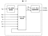
- FIG. 17 is a diagram showing an outline of the abnormal combustion determination and avoidance control logic executed in the ECU 20 of the engine control apparatus according to the third embodiment of the present invention.
- the knock / misfire determination unit is provided with an accelerator opening sensor 16 as an input signal. Is a feature. Based on the accelerator opening sensor 16, the knock / misfire determination unit determines whether or not the current operating state is a steady state, and changes the method for setting the knock / misfire determination threshold based on the result.
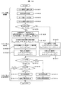
- step S1801 the ECU 20 reads the ion signal 4g.
- step S1802 an ion signal calculation period is set. Basically, the calculation period is set from the elapse of a certain time (for example, 2 ms) from the ignition timing to the timing (for example, 90 deg. ATDC) at which combustion ends. This calculation period is stored in advance as a map for each operating condition.
- step S1803 an ion signal peak value C (i) is calculated.
- the symbol i means the i-th cycle.
- step S1804 the accelerator opening ⁇ is read.
- step S1805 it is determined whether the current steady state is obtained by comparing the change amount d ⁇ / dt of the accelerator opening with the predetermined value X.
- step S1806 the intake pipe pressure P in , air-fuel ratio A / F, intake valve closing timing ⁇ IVC , exhaust valve closing timing ⁇ EVC , ignition
- the timing ⁇ spk and the EGR valve opening ⁇ are read.
- step S1807 the normal combustion maximum in-cylinder temperature Tmax is calculated from the read parameters. Specifically, first, the in-cylinder air amount and the internal EGR amount are obtained from the exhaust valve closing timing, the intake pipe pressure, and the EGR valve opening.
- the in-cylinder temperature history of the air cycle in the compression / expansion stroke is obtained from the effective compression ratio obtained from the intake valve closing timing, the in-cylinder air amount, and the internal EGR amount. Based on the in-cylinder temperature history of the air cycle, the amount of heat generated during combustion obtained from the air-fuel ratio, and the combustion end timing that can be estimated from the ignition timing, the maximum in-cylinder temperature T max during normal combustion is calculated. .
- the normal combustion ion signal peak value C b (i) is calculated from the maximum in-cylinder temperature T max during normal combustion.
- the ECU 20 stores in advance a formula (approximate formula) of the relationship between the maximum in-cylinder temperature and the ion signal shown in FIG. 6, and the calculation is performed using the formula.
- a knock determination threshold value C k (i) and a misfire determination threshold value C m (i) are calculated from the normal combustion ion signal peak value C b (i).
- the normal combustion ion signal integrated value C b (i) multiplied by the constant A is set to the knock determination threshold C k (i)
- the normal combustion ion signal integrated value C b (i) is set to the constant B.
- the multiplied value is defined as a misfire determination threshold value C m (i).
- A is set to about 1.2 to 2.0
- B is set to about 0.1 to 0.5.
- step S1810 the background level of the ion signal peak value is calculated.
- the background level means an average value of ion signal peak values for n cycles before the current cycle. Since the in-cylinder state is stable under steady conditions, the background level that is the average value for the past n cycles can be considered as the ion current peak value during normal combustion.
- n is set to about 5 to 30.
- step S1811 a knock determination threshold value C k (i) and a misfire determination threshold value C m (i) are calculated from the background level C bg (i).
- a value obtained by multiplying the background level C bg (i) by a constant A is a knock determination threshold value C k (i)
- a value obtained by multiplying the background level C bg (i) by a constant B is a misfire determination threshold value.
- C m (i) is set to about 1.2 to 2.0
- B is set to about 0.1 to 0.5.
- step S1812 When the steady state and the non-steady state are set, knock and misfire determination threshold values are set by different methods, respectively, and then, in step S1812, the ion signal peak value C (i) and the knock determination threshold value C k are set. By comparing (i), it is determined whether or not it is a knock. If C (i)> C k (i), it is determined that it is knocking, and the process proceeds to step S1813. If a C (i) ⁇ C k ( i) is determined not to be knocked, the process proceeds to step S1815. In step S1813, ignition timing retardation control is performed to avoid knocking, and in step S1814, intake valve closing timing retardation control (decrease in the effective compression ratio) is performed to avoid knocking.
- step S1812 If it is determined in step S1812 that the engine is not knocked, the process proceeds to step S1815, and the ion signal peak value C (i) is compared with the misfire determination threshold value C m (i) to determine whether or not the misfire has occurred. If C (i) ⁇ C m (i), it is determined that there is no misfire, and the series of controls is terminated. If C (i) ⁇ C m (i), it is determined that a misfire has occurred, and the process proceeds to step S1816. In step S1816, ignition timing advance control is performed to avoid misfire, and in step S1817, intake valve close timing advance control (increase in effective compression ratio) is performed to avoid misfire. Then, a series of control is finished.
- the present invention is not limited to this, and the time change amount of the intake pipe pressure or the intake valve closing timing is used. Also good.
- a certain period (for example, 100 ms) may be determined as a transient state from the time when the change in the accelerator opening occurs.
Landscapes
- Engineering & Computer Science (AREA)
- Chemical & Material Sciences (AREA)
- Combustion & Propulsion (AREA)
- Mechanical Engineering (AREA)
- General Engineering & Computer Science (AREA)
- Physics & Mathematics (AREA)
- General Physics & Mathematics (AREA)
- Combined Controls Of Internal Combustion Engines (AREA)
- Ignition Installations For Internal Combustion Engines (AREA)
- Output Control And Ontrol Of Special Type Engine (AREA)
- Electrical Control Of Ignition Timing (AREA)
Priority Applications (3)
| Application Number | Priority Date | Filing Date | Title |
|---|---|---|---|
| EP13781570.0A EP2843221B1 (de) | 2012-04-26 | 2013-03-13 | Motorsteuerungsvorrichtung |
| CN201380021946.XA CN104254682B (zh) | 2012-04-26 | 2013-03-13 | 发动机控制装置 |
| US14/396,508 US9702779B2 (en) | 2012-04-26 | 2013-03-13 | Engine control device |
Applications Claiming Priority (2)
| Application Number | Priority Date | Filing Date | Title |
|---|---|---|---|
| JP2012-100537 | 2012-04-26 | ||
| JP2012100537A JP6055608B2 (ja) | 2012-04-26 | 2012-04-26 | エンジン制御装置 |
Publications (1)
| Publication Number | Publication Date |
|---|---|
| WO2013161415A1 true WO2013161415A1 (ja) | 2013-10-31 |
Family
ID=49482755
Family Applications (1)
| Application Number | Title | Priority Date | Filing Date |
|---|---|---|---|
| PCT/JP2013/056897 Ceased WO2013161415A1 (ja) | 2012-04-26 | 2013-03-13 | エンジン制御装置 |
Country Status (5)
| Country | Link |
|---|---|
| US (1) | US9702779B2 (de) |
| EP (1) | EP2843221B1 (de) |
| JP (1) | JP6055608B2 (de) |
| CN (1) | CN104254682B (de) |
| WO (1) | WO2013161415A1 (de) |
Cited By (1)
| Publication number | Priority date | Publication date | Assignee | Title |
|---|---|---|---|---|
| RU2667096C1 (ru) * | 2013-12-12 | 2018-09-14 | Рено С.А.С. | Устройство и способ контроля работы клапана рециркуляции выхлопных газов с помощью механизма опережения зажигания |
Families Citing this family (22)
| Publication number | Priority date | Publication date | Assignee | Title |
|---|---|---|---|---|
| CN105008702B (zh) * | 2012-12-10 | 2017-11-17 | 沃尔沃卡车公司 | 燃料温度推定装置 |
| JP5931844B2 (ja) * | 2013-12-27 | 2016-06-08 | 三菱重工業株式会社 | 油圧機械の診断システム及び診断方法並びに油圧トランスミッション及び風力発電装置 |
| US9926904B2 (en) * | 2014-10-03 | 2018-03-27 | Cummins, Inc. | Variable ignition energy management |
| US10451523B2 (en) * | 2014-11-20 | 2019-10-22 | Ford Global Technologies, Llc | Misfire detection with crankshaft vibrations |
| CN104564483A (zh) * | 2015-01-04 | 2015-04-29 | 同济大学 | 一种检测火花塞点火式发动机早燃的检测装置和检测方法 |
| EP3362663B1 (de) | 2015-10-14 | 2026-03-11 | Cummins, Inc. | Referenzwertmotorsteuerungssysteme und -verfahren |
| WO2017065753A1 (en) * | 2015-10-14 | 2017-04-20 | Cummins Inc. | Reference value engine control systems and methods |
| CN108779729B (zh) | 2015-10-14 | 2021-11-30 | 康明斯公司 | 用于控制内燃机的系统以及控制器 |
| US10947914B2 (en) | 2015-10-14 | 2021-03-16 | Cummins Inc. | Reference value engine control systems and methods |
| WO2017065757A1 (en) | 2015-10-14 | 2017-04-20 | Cummins Inc. | Hierarchical engine control systems and methods |
| FR3048263B1 (fr) * | 2016-02-26 | 2018-03-16 | Peugeot Citroen Automobiles Sa | Procede de controle de combustion d'un moteur thermique par un procede de baisse de charge immediate |
| DE102016216531A1 (de) * | 2016-09-01 | 2018-03-01 | Robert Bosch Gmbh | Verfahren zur Klopferkennung einer Brennkraftmaschine |
| JP2019210834A (ja) * | 2018-06-01 | 2019-12-12 | トヨタ自動車株式会社 | 内燃機関の制御装置 |
| US10815919B2 (en) * | 2018-09-27 | 2020-10-27 | Cummins Inc. | Engine control based on combustion misfire of exhaust gas recirculation cylinder |
| WO2020236154A1 (en) | 2019-05-21 | 2020-11-26 | Cummins Inc. | Variable energy ignition methods, systems, methods, and apparatuses |
| JP6852754B2 (ja) * | 2019-06-17 | 2021-03-31 | トヨタ自動車株式会社 | 燃料噴射制御装置 |
| JP7222869B2 (ja) * | 2019-10-24 | 2023-02-15 | 日立Astemo株式会社 | 内燃機関制御装置 |
| WO2021260444A1 (en) * | 2020-06-25 | 2021-12-30 | Tvs Motor Company Limited | Event detection system |
| GB2597965B (en) * | 2020-08-12 | 2022-11-23 | Caterpillar Energy Solutions Gmbh | Misfire classification method and control unit for an internal combustion engine |
| CN111963352A (zh) * | 2020-09-10 | 2020-11-20 | 重庆重客检测技术有限公司 | 一种基于离子流的内燃机点火判定方法 |
| DE102020128281A1 (de) * | 2020-10-28 | 2022-04-28 | Bayerische Motoren Werke Aktiengesellschaft | Verfahren zur robusten Klopferkennung in einer Verbrennungskraftmaschine, Steuergerät und Kraftfahrzeug |
| CN115711180B (zh) * | 2022-10-31 | 2024-09-24 | 东风汽车集团股份有限公司 | 发动机异常工况egr率与节气门协同控制方法及系统 |
Citations (7)
| Publication number | Priority date | Publication date | Assignee | Title |
|---|---|---|---|---|
| JPH0534244A (ja) * | 1991-08-01 | 1993-02-09 | Hitachi Ltd | 内燃機関の燃焼状態検出装置 |
| JPH06323191A (ja) * | 1993-05-18 | 1994-11-22 | Toyota Motor Corp | 内燃機関のノッキング制御装置 |
| JPH10103210A (ja) * | 1996-09-27 | 1998-04-21 | Toyota Motor Corp | 内燃機関のノッキング検出装置 |
| JP2001041096A (ja) * | 1999-07-23 | 2001-02-13 | Denso Corp | 燃料噴射ノズル |
| JP2003184725A (ja) * | 2001-12-20 | 2003-07-03 | Honda Motor Co Ltd | 内燃機関の失火検出装置 |
| JP2003184635A (ja) * | 2001-12-20 | 2003-07-03 | Fuji Heavy Ind Ltd | イオン電流を用いたエンジンの失火検出装置及び該装置に用いられるプログラムを記録した記録媒体 |
| JP2008101591A (ja) * | 2006-10-20 | 2008-05-01 | Toyota Motor Corp | 内燃機関の着火時期制御装置 |
Family Cites Families (14)
| Publication number | Priority date | Publication date | Assignee | Title |
|---|---|---|---|---|
| US5241937A (en) * | 1991-12-09 | 1993-09-07 | Honda Giken Kogyo Kabushiki Kaisha | Misfire-detecting system for internal combustion engines |
| DE4333965A1 (de) * | 1993-10-05 | 1995-04-06 | Bosch Gmbh Robert | Verfahren zur Klopferkennung |
| JP2000130246A (ja) | 1998-10-27 | 2000-05-09 | Daihatsu Motor Co Ltd | 内燃機関のノック検出方法 |
| DE10032702C2 (de) * | 2000-07-05 | 2003-10-30 | Conti Temic Microelectronic | Verfahren zur Erkennung klopfender Verbrennung beim Betrieb einer Brennkraftmaschine |
| US6611145B2 (en) | 2000-07-20 | 2003-08-26 | Harley-Davidson Motor Company Group, Inc. | Motorcycle having a system for combustion diagnostics |
| US7134423B2 (en) * | 2002-11-01 | 2006-11-14 | Visteon Global Technologies, Inc. | Ignition diagnosis and combustion feedback control system using an ionization signal |
| JP3827083B2 (ja) | 2002-11-08 | 2006-09-27 | 三菱電機株式会社 | 内燃機関のノック検出装置 |
| US7290442B2 (en) * | 2004-08-25 | 2007-11-06 | Visteon Global Technologies, Inc. | Method and system of estimating MBT timing using in-cylinder ionization signal |
| JP4799200B2 (ja) * | 2006-02-06 | 2011-10-26 | ダイハツ工業株式会社 | 内燃機関のイオン電流に基づく運転制御方法 |
| JP4490455B2 (ja) * | 2006-10-06 | 2010-06-23 | トヨタ自動車株式会社 | 内燃機関のノッキング判定装置、ノッキング判定方法、その方法を実現するプログラムおよびそのプログラムを記録した記録媒体 |
| JP2010065569A (ja) * | 2008-09-09 | 2010-03-25 | Toyota Industries Corp | 内燃機関の燃料噴射制御装置 |
| JP2011085081A (ja) * | 2009-10-16 | 2011-04-28 | Daihatsu Motor Co Ltd | エンジンの失火判定方法 |
| JP5334791B2 (ja) | 2009-10-19 | 2013-11-06 | 三菱電機株式会社 | 内燃機関の制御装置 |
| US8977475B2 (en) * | 2012-04-24 | 2015-03-10 | Cummins Inc. | Control system for a model-based knock suppression system using a multiple actuation strategy |
-
2012
- 2012-04-26 JP JP2012100537A patent/JP6055608B2/ja not_active Expired - Fee Related
-
2013
- 2013-03-13 EP EP13781570.0A patent/EP2843221B1/de not_active Not-in-force
- 2013-03-13 WO PCT/JP2013/056897 patent/WO2013161415A1/ja not_active Ceased
- 2013-03-13 CN CN201380021946.XA patent/CN104254682B/zh not_active Expired - Fee Related
- 2013-03-13 US US14/396,508 patent/US9702779B2/en not_active Expired - Fee Related
Patent Citations (7)
| Publication number | Priority date | Publication date | Assignee | Title |
|---|---|---|---|---|
| JPH0534244A (ja) * | 1991-08-01 | 1993-02-09 | Hitachi Ltd | 内燃機関の燃焼状態検出装置 |
| JPH06323191A (ja) * | 1993-05-18 | 1994-11-22 | Toyota Motor Corp | 内燃機関のノッキング制御装置 |
| JPH10103210A (ja) * | 1996-09-27 | 1998-04-21 | Toyota Motor Corp | 内燃機関のノッキング検出装置 |
| JP2001041096A (ja) * | 1999-07-23 | 2001-02-13 | Denso Corp | 燃料噴射ノズル |
| JP2003184725A (ja) * | 2001-12-20 | 2003-07-03 | Honda Motor Co Ltd | 内燃機関の失火検出装置 |
| JP2003184635A (ja) * | 2001-12-20 | 2003-07-03 | Fuji Heavy Ind Ltd | イオン電流を用いたエンジンの失火検出装置及び該装置に用いられるプログラムを記録した記録媒体 |
| JP2008101591A (ja) * | 2006-10-20 | 2008-05-01 | Toyota Motor Corp | 内燃機関の着火時期制御装置 |
Cited By (1)
| Publication number | Priority date | Publication date | Assignee | Title |
|---|---|---|---|---|
| RU2667096C1 (ru) * | 2013-12-12 | 2018-09-14 | Рено С.А.С. | Устройство и способ контроля работы клапана рециркуляции выхлопных газов с помощью механизма опережения зажигания |
Also Published As
| Publication number | Publication date |
|---|---|
| US9702779B2 (en) | 2017-07-11 |
| US20150128683A1 (en) | 2015-05-14 |
| CN104254682A (zh) | 2014-12-31 |
| EP2843221B1 (de) | 2018-05-16 |
| JP2013227921A (ja) | 2013-11-07 |
| CN104254682B (zh) | 2017-08-22 |
| JP6055608B2 (ja) | 2016-12-27 |
| EP2843221A4 (de) | 2016-01-20 |
| EP2843221A1 (de) | 2015-03-04 |
Similar Documents
| Publication | Publication Date | Title |
|---|---|---|
| JP6055608B2 (ja) | エンジン制御装置 | |
| US9194313B2 (en) | Spark-ignition engine and method of controlling the spark-ignition engine | |
| EP3004604B1 (de) | Fehlzündungsdetektor für einen verbrennungsmotor | |
| US7822536B2 (en) | Start-up control device for internal combustion engine | |
| US10132287B2 (en) | Ignition control system | |
| JP4873249B2 (ja) | 車両用エンジンの制御装置 | |
| JP6764824B2 (ja) | 内燃機関の点火制御装置 | |
| CN110300845B (zh) | 点火控制系统 | |
| JP4868242B2 (ja) | 車両用エンジンの制御装置 | |
| JP6854581B2 (ja) | 内燃機関の制御装置 | |
| JP5087569B2 (ja) | 圧縮自己着火式内燃機関の制御装置 | |
| JP6022594B2 (ja) | エンジン制御システム | |
| US20160348596A1 (en) | Ignition device and ignition method for internal combustion engine | |
| JP6476102B2 (ja) | 内燃機関の制御装置 | |
| JP2006009720A (ja) | 内燃機関の点火時期制御装置 | |
| WO2012086398A1 (ja) | 内燃機関の制御装置 | |
| JP6527393B2 (ja) | 内燃機関の制御装置 | |
| JP5896839B2 (ja) | 内燃機関の制御装置 | |
| JP2016056684A (ja) | エンジン制御装置 | |
| JP4803117B2 (ja) | 内燃機関の始動制御装置 | |
| JP2023183598A (ja) | エンジン制御装置 | |
| JP2016109100A (ja) | 内燃機関の診断装置 | |
| JP2007239564A (ja) | 内燃機関の制御装置 |
Legal Events
| Date | Code | Title | Description |
|---|---|---|---|
| 121 | Ep: the epo has been informed by wipo that ep was designated in this application |
Ref document number: 13781570 Country of ref document: EP Kind code of ref document: A1 |
|
| WWE | Wipo information: entry into national phase |
Ref document number: 14396508 Country of ref document: US Ref document number: 2013781570 Country of ref document: EP |
|
| NENP | Non-entry into the national phase |
Ref country code: DE |