WO2013162005A1 - Raccord de tuyau, robinet de fermeture et outil de desserrage - Google Patents
Raccord de tuyau, robinet de fermeture et outil de desserrage Download PDFInfo
- Publication number
- WO2013162005A1 WO2013162005A1 PCT/JP2013/062415 JP2013062415W WO2013162005A1 WO 2013162005 A1 WO2013162005 A1 WO 2013162005A1 JP 2013062415 W JP2013062415 W JP 2013062415W WO 2013162005 A1 WO2013162005 A1 WO 2013162005A1
- Authority
- WO
- WIPO (PCT)
- Prior art keywords
- pipe
- fixing member
- joint
- tightening
- outer periphery
- Prior art date
- Legal status (The legal status is an assumption and is not a legal conclusion. Google has not performed a legal analysis and makes no representation as to the accuracy of the status listed.)
- Ceased
Links
Images
















Classifications
-
- F—MECHANICAL ENGINEERING; LIGHTING; HEATING; WEAPONS; BLASTING
- F16—ENGINEERING ELEMENTS AND UNITS; GENERAL MEASURES FOR PRODUCING AND MAINTAINING EFFECTIVE FUNCTIONING OF MACHINES OR INSTALLATIONS; THERMAL INSULATION IN GENERAL
- F16L—PIPES; JOINTS OR FITTINGS FOR PIPES; SUPPORTS FOR PIPES, CABLES OR PROTECTIVE TUBING; MEANS FOR THERMAL INSULATION IN GENERAL
- F16L19/00—Joints in which sealing surfaces are pressed together by means of a member, e.g. a swivel nut, screwed on, or into, one of the joint parts
- F16L19/08—Joints in which sealing surfaces are pressed together by means of a member, e.g. a swivel nut, screwed on, or into, one of the joint parts with metal rings which bite into the wall of the pipe
- F16L19/10—Joints in which sealing surfaces are pressed together by means of a member, e.g. a swivel nut, screwed on, or into, one of the joint parts with metal rings which bite into the wall of the pipe the profile of the ring being altered
-
- F—MECHANICAL ENGINEERING; LIGHTING; HEATING; WEAPONS; BLASTING
- F16—ENGINEERING ELEMENTS AND UNITS; GENERAL MEASURES FOR PRODUCING AND MAINTAINING EFFECTIVE FUNCTIONING OF MACHINES OR INSTALLATIONS; THERMAL INSULATION IN GENERAL
- F16L—PIPES; JOINTS OR FITTINGS FOR PIPES; SUPPORTS FOR PIPES, CABLES OR PROTECTIVE TUBING; MEANS FOR THERMAL INSULATION IN GENERAL
- F16L19/00—Joints in which sealing surfaces are pressed together by means of a member, e.g. a swivel nut, screwed on, or into, one of the joint parts
- F16L19/08—Joints in which sealing surfaces are pressed together by means of a member, e.g. a swivel nut, screwed on, or into, one of the joint parts with metal rings which bite into the wall of the pipe
- F16L19/10—Joints in which sealing surfaces are pressed together by means of a member, e.g. a swivel nut, screwed on, or into, one of the joint parts with metal rings which bite into the wall of the pipe the profile of the ring being altered
- F16L19/12—Joints in which sealing surfaces are pressed together by means of a member, e.g. a swivel nut, screwed on, or into, one of the joint parts with metal rings which bite into the wall of the pipe the profile of the ring being altered with additional sealing means
-
- F—MECHANICAL ENGINEERING; LIGHTING; HEATING; WEAPONS; BLASTING
- F16—ENGINEERING ELEMENTS AND UNITS; GENERAL MEASURES FOR PRODUCING AND MAINTAINING EFFECTIVE FUNCTIONING OF MACHINES OR INSTALLATIONS; THERMAL INSULATION IN GENERAL
- F16L—PIPES; JOINTS OR FITTINGS FOR PIPES; SUPPORTS FOR PIPES, CABLES OR PROTECTIVE TUBING; MEANS FOR THERMAL INSULATION IN GENERAL
- F16L57/00—Protection of pipes or objects of similar shape against external or internal damage or wear
- F16L57/005—Protection of pipes or objects of similar shape against external or internal damage or wear specially adapted for the ends of pipes
-
- F—MECHANICAL ENGINEERING; LIGHTING; HEATING; WEAPONS; BLASTING
- F25—REFRIGERATION OR COOLING; COMBINED HEATING AND REFRIGERATION SYSTEMS; HEAT PUMP SYSTEMS; MANUFACTURE OR STORAGE OF ICE; LIQUEFACTION SOLIDIFICATION OF GASES
- F25B—REFRIGERATION MACHINES, PLANTS OR SYSTEMS; COMBINED HEATING AND REFRIGERATION SYSTEMS; HEAT PUMP SYSTEMS
- F25B41/00—Fluid-circulation arrangements
- F25B41/40—Fluid line arrangements
Definitions
- the present invention relates to a pipe joint and a closing valve.
- a closing valve for connecting the heat exchange device and the pipe.
- This closing valve includes a housing in which a flow path for refrigerant is formed, a valve function part for opening and closing the flow path, and a pipe joint (joint function part) for connecting a pipe.
- the current pipe joint is a form in which a tapered sealing surface is formed on the cylindrical joint body constituting one end of the flow path, and the diameter of the pipe is increased in the flare shape of the pipe.
- the deformed connection end is brought into close contact and tightened with a nut.
- the connection structure formed by the tapered seal surface and the flare-shaped connection end portion is likely to cause a refrigerant (such as chlorofluorocarbon) to leak out. Since leakage of refrigerant causes destruction of the global environment such as global warming and ozone layer destruction, measures to prevent refrigerant leakage in the heat exchange device are an important issue.
- Patent Document 1 a valve described in Patent Document 1 as a closing valve provided with a pipe joint that drastically suppresses the amount of refrigerant leakage.
- This pipe joint encloses a tubular joint body part constituting one end of the flow path, a tubular fastening member screwed into the joint body part, and a pipe inserted into the fastening member and the joint body part.
- a metal ferrule and a diameter reducing means are examples of reducing means.
- the diameter reducing means has a tapered surface that reduces the diameter in the pipe insertion direction.
- the ferrule is plastically deformed in the direction of diameter reduction by the taper surface, and tightly adheres to the inner periphery of the joint main body portion in an airtight manner, and bites into the play regulation state on the outer periphery of the pipe and becomes airtight. It is designed to be tightened in close contact.
- the structure in which the pipe is connected by reducing the diameter of the ferrule is very effective from the viewpoint of preventing leakage of the refrigerant.
- the above-described pipe joint is configured such that the fastening member is attached to the joint body by screwing.
- the operator performs a tightening operation by fitting the tool to the joint body with one hand and fitting the tool to the tightening member with the other hand.
- the inner diameter dimension of the joint body is provided with a clearance in order to facilitate the insertion of the pipe. Therefore, after inserting the pipe into the joint body, the pipe comes out of the joint body until the tool is fitted to the joint body and the fastening member and tightening is started, and workability is reduced. There is a concern to do.
- the first invention has been completed based on the above-described circumstances, and even if a general-purpose tool is used, the hermetic performance by the ferrule is not lost, and when necessary, the hermeticity by the ferrule can be released. It aims at providing a pipe joint.
- a second object of the present invention is to improve workability.
- the pipe joint of the first invention is It is a form that can communicate with the flow path of the refrigerant of the heat exchange device, and a tubular joint body part into which the pipe is inserted, A cylindrical fixing member attached to the joint body by screwing; When the fixing member is rotated in the tightening direction and screwed in, an axial pressing force is received from the fixing member to seal between the inner periphery of the joint main body and the outer periphery of the pipe in an airtight manner.
- Ferrules It is provided with a tightening nut capable of applying a rotational force in a tightening direction to the fixing member by fitting and rotating a general-purpose tool on a fitting portion formed on the outer periphery, Formed on the outer periphery of the fixing member, and the loosening screw portion of the joint main body portion and the fixing member screwed in the reverse direction of the screwing direction;
- a screw-in restricting part that abuts the loosening tool and restricts further screwing when the loosening tool is screwed into the loosening screw part and rotated in the direction opposite to the fastening direction of the fixing member; It has features where it is provided.
- the closing valve of the first invention is A housing attached to the heat exchange device; A refrigerant flow path formed in the housing; A valve body for opening and closing the flow path; A tubular joint body formed in the housing to communicate with the flow path and into which a pipe is inserted; A cylindrical fixing member attached to the joint body by screwing; When the fixing member is rotated in the tightening direction and screwed in, an axial pressing force is received from the fixing member to seal between the inner periphery of the joint main body and the outer periphery of the pipe in an airtight manner.
- Ferrules It is provided with a tightening nut capable of applying a rotational force in a tightening direction to the fixing member by fitting and rotating a general-purpose tool on a fitting portion formed on the outer periphery, Formed on the outer periphery of the fixing member, and the loosening screw portion of the joint main body portion and the fixing member screwed in the reverse direction of the screwing direction;
- a screw-in restricting part that abuts the loosening tool and restricts further screwing when the loosening tool is screwed into the loosening screw part and rotated in the direction opposite to the fastening direction of the fixing member; It has features where it is provided.
- the pipe joint of the second invention is A tubular joint main body portion that is in communication with the refrigerant flow path of the heat exchange device, and the hollow interior is an insertion space for inserting a pipe;
- a cylindrical fastening member that is attached to the joint main body portion by screwing and constitutes the insertion space;
- a ferrule that seals between the inner periphery of the joint body and the outer periphery of the pipe in an airtight manner by receiving axial pressing force from the tightening member screwed in the tightening direction.
- It has a feature in that it has holding means capable of holding the pipe in a retaining state by contacting the pipe inserted into the insertion space.
- the closing valve of the second invention is A housing attached to the heat exchange device; A refrigerant flow path formed in the housing; A valve body for opening and closing the flow path; A tubular joint body formed in the housing so as to communicate with the flow path, and a hollow interior serving as an insertion space for inserting a pipe; A cylindrical fastening member that is attached to the joint main body portion by screwing and constitutes the insertion space; A closing valve provided with a ferrule that seals between the inner periphery of the joint main body and the outer periphery of the pipe in an airtight manner by receiving axial pressing force from the tightening member screwed in the tightening direction.
- It has a feature in that it has holding means capable of holding the pipe in a retaining state by contacting the pipe inserted into the insertion space.
- the general-purpose tool means a tool that can be fitted into a regular hexagonal outer peripheral shape such as a spanner or a monkey wrench.
- the loosening tool when releasing the airtightness by the ferrule and removing the pipe, the loosening tool is screwed into the loosening screw part, rotated in the direction opposite to the tightening direction of the fixing member, and brought into contact with the screwing restriction part. Then, the loosening tool is restricted from further screwing operation, that is, relative rotation with respect to the fixing member. Therefore, if the loosening tool is further rotated from this state, the fixing member is integrated with the loosening tool and rotated in the direction opposite to the tightening direction, that is, in the loosening direction.
- the airtightness due to the ferrule can be released by using a dedicated relaxation tool.
- the pipe joint and closing valve of the second invention can hold the pipe inserted into the insertion space in a retaining state by the holding means. Therefore, there is no possibility that the pipe will come out of the insertion space between the time when the pipe is inserted into the insertion space and the time when the tightening operation of the tightening member is started, and the workability is excellent.
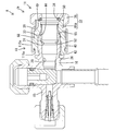
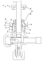
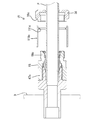
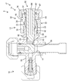
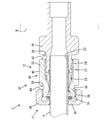
- Sectional drawing showing the state which attached the separation
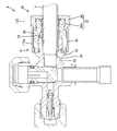
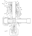
- Sectional view showing the state where the loosened nut is restricted from being disengaged from the joint body by the disengagement restricting member
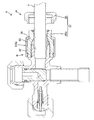
- Sectional view showing the state where the separation regulating member is removed from the housing
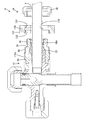
- Sectional view showing the state of holding the pipe inserted into the joint body
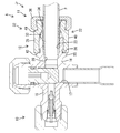
- Cross-sectional view showing the correct connection of the pipe to the fitting
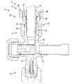
- Sectional view showing how the fixing member does not loosen when the tightening nut is removed while the pipe is connected
- Sectional view showing the state that the tightening nut is removed, the cover is moved backward, and the relaxation tool is passed through the pipe Sectional view showing the state where the relaxation tool is screwed into the fixing member Sectional drawing which shows the state which removed the fixing member from the joint main-body part with the tool for relaxation
- Sectional drawing of Example 8 Sectional drawing of Example 9 Sectional drawing of Example 10 Sectional drawing of Example 11 Sectional drawing of Example 12 Sectional drawing showing the state which attached the separation
- Sectional view showing the state where the loosened nut is restricted from being disengaged from the joint body by the disengagement restricting member Sectional view showing the state where the separation regulating member is removed from the housing
- Cross-sectional view showing the correct connection of the pipe to the fitting Sectional view showing how the fixing member does not loosen even when the tightening nut is loosened with the pipe connected
- the relaxation tool of the first invention is It is a form that can communicate with the flow path of the refrigerant of the heat exchange device, and a tubular joint body part into which the pipe is inserted, A cylindrical fixing member attached to the joint body by screwing; When the fixing member is rotated in the tightening direction and screwed in, an axial pressing force is received from the fixing member to seal between the inner periphery of the joint main body and the outer periphery of the pipe in an airtight manner.
- a tightening nut capable of applying a rotational force in the tightening direction to the fixing member by fitting and rotating a general-purpose tool on a fitting portion formed on the outer periphery; Formed on the outer periphery of the fixing member, and the loosening screw portion of the joint main body portion and the fixing member screwed in the reverse direction of the screwing direction; Used for pipe fittings with a screw-in restriction, When the screw is screwed into the loosening screw part and rotated in the direction opposite to the fastening direction of the fixing member, the screwing tool is further restricted by coming into contact with the screwing restriction part.
- a relaxing female screw portion that can be screwed into the relaxing screw portion; It is a form in which a part in the circumferential direction is notched and the outer periphery and the inner periphery are communicated with each other, and a communicating part in which the notch dimension is set larger than the outer diameter of the pipe may be provided. According to this configuration, when the relaxation tool is screwed into the relaxation screw portion, the pipe is passed through the communicating portion without cutting the pipe, so that the relaxation tool is coaxial with the relaxation screw portion. Can be arranged.
- the pipe joint and the closing valve of the first invention are: A cover that is movable between a position that covers the loosening screw portion and a position that exposes the loosening screw portion may be attached to the fixing member. According to this configuration, when the relaxation tool is not screwed into the relaxation screw portion, the relaxation screw portion can be protected by the cover.
- the pipe joint and the closing valve of the first invention are:
- a locking device may be provided that restricts the rotation of the fixing member in the loosening direction and maintains an airtight seal state by the ferrule. According to this configuration, even when a rotational force is applied to the fixing member with a general-purpose tool in a state in which the pipe is connected, the fixing member is restricted from rotating in the loosening direction for releasing the pressure on the ferrule by the locking means. The Therefore, according to the present invention, the reliability of the hermetic sealing performance by the ferrule is excellent.
- the pipe joint and the closing valve of the second invention are
- the holding means may be arranged at a position facing the insertion space. According to this structure, since the holding means is not exposed to the outer surface of the closing valve, it is protected from the interference of foreign matter.
- the pipe joint and the closing valve of the second invention are
- the fastening member is A cylindrical fixing member that abuts against the ferrule and applies a pressing force; It is configured to include a tightening nut that is screwed into the fixing member and is applied with a screwing force in a tightening direction to apply a pressing force to the fixing member toward the ferrule side,
- the holding means is disposed so as to be sandwiched between the fixing member and the tightening nut in the axial direction, and is elastically attached to the outer periphery of the pipe by being reduced in diameter by screwing the tightening nut in the tightening direction. It may be a ring.
- the elastic ring is not reduced in diameter before the pipe is inserted, the frictional resistance is reduced when the pipe is inserted, so that workability is improved.
- the pipe can be held in the retaining state by the elastic ring by screwing the tightening nut in the tightening direction.
- the pipe joint and the closing valve of the second invention are
- the tightening nut and the fixing member may be formed with detection portions that come into contact with each other when screwing of the tightening nut proceeds to a state where the elastic ring can hold the pipe. .
- the pipe can be reliably held by screwing the tightening nut until the detection parts come into contact with each other. Therefore, if it is determined as a work manual that the tightening nut is screwed in until the detecting parts come into contact with each other, even a non-skilled person can reliably perform the pipe holding work.
- the pipe joint and the closing valve of the second invention are A tapered surface is formed on the inner periphery of the joint main body, the diameter of which decreases toward the front in the insertion direction of the pipe, and abuts the tip of the pipe that is normally inserted into the insertion space.
- the holding means may be arranged behind the tapered surface in the insertion direction of the pipe. According to this configuration, the pipe that is normally inserted into the insertion space has its tip abutted against the tapered surface, and is held in a retaining state by the holding means. Since the abutting position on the tapered surface and the holding position by the holding means are spaced from each other in the pipe insertion direction, the pipe is maintained in a stable posture without being inclined with respect to the axis.
- the pipe joint Ja includes an outdoor unit B that is a heat exchanger provided with a compressor and a condenser, and an indoor unit that is a heat exchanger (not shown) provided with an expansion valve and an evaporator. This is applied to a domestic air conditioner (heat exchange device) connected by a pipe P made of (copper alloy).
- a circulation path is configured by the outdoor unit B, the indoor unit, and the pipe P, and refrigerant (fluorocarbon) circulates in the circulation path, whereby heat exchange is performed.
- the pipe joint Ja is for connecting the pipe P to the closing valve A of the outdoor unit B.
- the pipe joint Ja is provided integrally with the closing valve A as a joint function part constituting the closing valve A.
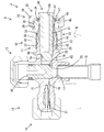
- the closing valve A is structurally configured to include a valve body 10 and a lock member 11.
- the closing valve A functionally includes a pipe joint Ja, a first valve function part 13 and a second valve function part 14.
- the pipe joint Ja can function as a single-function pipe joint by being separated from the valve function parts 13 and 14.
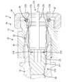
- the valve body 10 includes a brass housing 15, a first valve function part 13 (open / close valve), a second valve function part 14 (service valve), and a joint body part 16. Inside the housing 15, there are a flow path 17 that is bent in a substantially L shape (substantially right angle) and whose both ends are open to the outer surface of the housing 15, and a branch path 18 that communicates with the flow path 17 and opens to the outer surface of the housing 15. Is formed.
- the closing valve A is fixed in a form exposed on the outer surface of the outdoor unit B.
- One end of the flow path 17 is fixed in an airtight manner to a connecting pipe 19 of a compressor (not shown) of the outdoor unit B by means such as brazing.
- the valve When the first valve body 20 of the first valve function unit 13 is manually operated, the valve is switched between an open state that allows the refrigerant to flow in the flow path 17 and a closed state that restricts the flow of the refrigerant in the flow path 17. be able to. Further, when the second valve body 21 of the second valve function unit 14 is manually operated, the inside of the branch path 18, the insertion space 23 connected to the branch path 18, and the pipe P can be evacuated.
- the pipe joint Ja includes a tubular joint body 16 and a joint function part 12.
- the joint function unit 12 includes a diameter-reducing means 22 including a rear tapered surface 31 (see FIG. 9) and a cylindrical lock member 11.
- the inside of the hollow of the pipe joint Ja is in a form that communicates with the end of the flow path 17 and is open to the rear end face (tip face) of the joint main body 16, and becomes an insertion space 23 for inserting the pipe P. ing.
- the joint body 16 is integrally formed with the housing 15 and protrudes from the outer surface of the housing 15 in a cylindrical shape.
- the direction parallel to the insertion / extraction direction of the pipe P with respect to the pipe joint Ja is defined as the front-rear direction.
- the insertion / extraction direction of the pipe P is parallel to the direction in which the fastening member 32 moves while rotating.
- the front of the pipe P with respect to the pipe joint Ja in the insertion direction (left side in FIGS. 1 to 10) is simply referred to as “front”, and the rear of the pipe P in the insertion direction with respect to the pipe joint Ja is simply referred to as “rear”.
- the “front-rear direction” and the “axial direction” of the pipe joint Ja (joint body portion 16) are used synonymously.
- a second male screw portion 24 is formed on the outer periphery of the rear end portion of the joint main body portion 16, and a concentric circular enlarged diameter portion 25 is provided at a position in front of the second male screw portion 24 on the outer periphery of the joint main body portion 16. Is formed.
- the rear end surface of the enlarged diameter portion 25 is a detection receiving portion 26 that is a flat surface orthogonal to the axial direction.
- the rear end surface of the joint main body portion 16 is a flat surface that is perpendicular to the insertion / extraction direction of the pipe P. As shown in FIG. 9, the inner peripheral edge of the flat surface (that is, the peripheral edge serving as a boundary with the rear tapered surface 31 described later) is an edge-shaped corner edge 27.
- the inner peripheral surface of the joint main body portion 16 is, in order from the front end portion toward the rear end portion, a third female screw portion 28, a front tapered surface 29, a constant diameter surface 30,
- the rear tapered surface 31 is configured.
- the front taper surface 29 has a tapered shape that gradually decreases in diameter toward the front.
- the inner diameter of the front end of the front tapered surface 29 is smaller than the outer diameter of the pipe P, and the inner diameter of the rear end of the front tapered surface 29 is slightly larger than the outer diameter of the pipe P.
- the constant diameter surface 30 has a constant inner diameter from the front end to the rear end.
- the rear taper surface 31 is gradually reduced in diameter toward the front, and the inner diameter of the front end of the rear taper surface 31 is the same as the maximum inner diameter of the constant diameter surface 30 and the front taper surface 29.
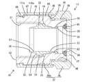
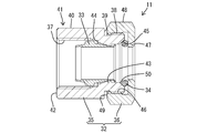
- the lock member 11 is configured by assembling a cylindrical fastening member 32, a cylindrical ferrule 33, a circular elastic ring 34, and a cylindrical cover 110 a. ing.
- the tightening member 32 is composed of two parts, a fixing member 66a made of brass and a tightening nut 36 made of brass.
- a second female screw portion 37 whose spiral direction is a right-hand thread is formed in the front end region on the inner periphery of the fixing member 66a.
- the right-hand thread refers to a mating member (joint body portion 16) while rotating a member (fixing member 66a) on which the right-hand thread is formed in a clockwise direction when viewed from the operator side (hereinafter referred to as a right turn).
- the member (fixing member 66a) is defined as a spiral form that moves away from the operator.
- the fixing member 66a is coaxially fitted from the rear to the joint main body 16 so that the second female screw portion 37 is fitted to the second male screw portion 24, and is screwed in while rotating clockwise as viewed from the rear. 16 is assembled. Therefore, the direction of the spiral of the second male screw portion 24 is also a right screw.
- a first male screw portion 38 is formed at the rear end of the outer periphery of the fixing member 66a in the same way as the second female screw portion 37.
- a pressure receiving portion 39 is formed at a position in front of the first male screw portion 38 on the outer periphery of the fixing member 66a so as to form a plane perpendicular to the axial direction and face the rear.
- a region in front of the pressure receiving portion 39 in the fixing member 66 a is a large diameter portion 67 having a larger outer diameter than the first male screw portion 38.
- a loose male screw portion 68 is formed at the outer peripheral rear end portion of the large diameter portion 67.
- the direction of the spiral of the male screw portion for relaxation 68 is a left-hand screw, contrary to the second female screw portion 37.
- the left-handed screw is a counterclockwise view of a member (fixing member 66a) in which the left-handed screw is formed and a mating member (relaxation female thread portion 133 of the relaxation tool 130 described later) viewed from the operator side. It is defined as a spiral form in which the mating member (relaxation tool 130) moves away from the operator forward when it is screwed while rotating in the turning direction (hereinafter referred to as left rotation).
- the region excluding the front end portion and the loosening male screw portion 68 is a circumferential surface region 40.
- the cross-sectional shape perpendicular to the axial direction of the circumferential surface region 40 is a true circle.
- the outer diameter dimension of the circumferential surface region 40 is the same as the maximum outer diameter dimension of the male screw portion 68 for relaxation.
- the circumferential surface region 40 constitutes a locking means 41 for restricting the fixing member 66a from displacing in the direction in which the pressing against the ferrule 33 is released.
- a circumferential positioning groove 69 that is continuous over the entire circumference is formed at the front end of the outer periphery of the large-diameter portion 67.
- the front end surface of the fixing member 66a (the surface facing the detection receiving portion 26 of the joint main body portion 16 in the axial direction) is a flat abutting portion 42 orthogonal to the axial direction.
- the abutting portion 42 approaches and separates from the detection receiving portion 26 in the process of screwing the fixing member 66a in the tightening direction and moving the fixing member 66a in the axial direction, and also comes into contact with the detection receiving portion 26 (surface contact). It comes to contact with.
- a locking portion 43 that protrudes concentrically inward over the entire circumference is formed in a region behind the second female screw portion 37 on the inner circumference of the fixing member 66 a.
- a flat pressing surface 44 facing forward is formed at a position between the second female screw portion 37 and the locking portion 43 on the inner periphery of the fixing member 66a.
- the pressing surface 44 is perpendicular to the insertion / extraction direction of the pipe P, and is positioned so as to face the pressure receiving surface 55 with the ring-shaped main body 51 of the ferrule 33 interposed therebetween when the fixing member 66a is assembled to the joint main body 16.
- a notch portion 45 is formed so as to be tapered toward the front and open to the rear end surface of the fixing member 66a.
- the tightening nut 36 has a ring shape that is continuous over the entire circumference.
- a first female screw portion 46 whose spiral direction is a right-hand thread is formed at the front end portion of the inner periphery of the tightening nut 36.
- a small-diameter portion 47 having an inner diameter smaller than that of the first female screw portion 46 is formed concentrically at the rear end portion of the inner periphery of the tightening nut 36.
- the inner diameter of the small diameter portion 47 is the same as or slightly larger than the outer diameter of the pipe P.
- the outer periphery of the tightening nut 36 is a fitting portion 48 having a regular hexagonal shape.
- a general-purpose tool 120 can be fitted into the fitting portion 48.
- the general-purpose tool 120 means a tool that can be fitted into a regular hexagonal outer peripheral shape such as a spanner or a monkey wrench and can rotate the fitting target member. Further, the front end surface of the tightening nut 36 has a flat shape perpendicular to the axial direction and serves as a pressing portion 49 facing forward.
- the tightening nut 36 is assembled to the fixing member 66a from the rear by screwing the first female thread 46 into the first male thread 38 while rotating the first female thread 46 clockwise as viewed from the rear (tightening direction). ing.
- the notch portion 45 and the small diameter portion 47 constitute a holding groove 50 that faces the inner periphery of the tightening member 32.
- the elastic ring 34 is attached to the holding groove 50.
- the elastic ring 34 is made of rubber and has an annular shape connected over the entire circumference.
- the inner diameter of the elastic ring 34 in a state where it is not elastically deformed is substantially the same as the outer diameter of the pipe P. That is, the inner diameter of the elastic ring 34 may be any of the same dimension as the outer diameter of the pipe P, a dimension larger than the outer diameter of the pipe P, and a dimension smaller than the outer diameter of the pipe P.
- the tightening nut 36 In the state before connecting the pipe P to the pipe joint Ja, as shown in FIGS. 1 to 3, the tightening nut 36 is in the initial position.
- the elastic ring 34 When the tightening nut 36 is in the initial position, the elastic ring 34 is not elastically deformed even if it is in contact with the notch 45 or the small diameter portion 47, or the amount of deformation is small even if elastically deformed.
- the tightening nut 36 is in the initial position, there is a space in the axial direction between the pressing portion 49 of the tightening nut 36 and the pressure receiving portion 39 of the fixing member 66a, and the rear end surface and the small diameter portion of the fixing member 66a. There is also a space between the front surface of 47.
- the ferrule 33 is made of brass, and is arranged coaxially with the joint body 16 and the fastening member 32 in the hollow of the fixing member 66a.
- the ferrule 33 has a cylindrical shape surrounding the pipe P inserted into the pipe joint Ja (insertion space 23).
- the minimum inner diameter of the ferrule 33 is larger than the outer diameter of the pipe P and has substantially the same inner diameter as the constant diameter surface 30.
- the ferrule 33 includes a thick ring-shaped main body 51, a cylindrical fastening portion 52 that is thinner than the ring-shaped main body 51 and extends forward from the ring-shaped main body 51,
- the holding portion 53 is thinner than the ring-shaped main body 51 and extends rearward from the ring-shaped main body 51.
- the outer peripheral part of the ring-shaped main body part 51 is expanded in steps from the outer periphery of the cylindrical fastening part 52 and the holding part 53.
- the front surface of the ring-shaped main body 51 is a seal surface 54 that has an angle close to a right angle to the axial direction but is reduced in diameter toward the front.
- the rear surface of the ring-shaped main body 51 is a pressure receiving surface 55 that is perpendicular to the axial direction.
- the outer peripheral surface of the cylindrical fastening portion 52 is inclined so as to reduce the diameter toward the front.
- the front end edge of the inner periphery of the cylindrical tightening portion 52 is a first biting portion 56.
- An edge-shaped second biting portion 57 that is pointed obliquely forward and inward is formed at a position behind the first biting portion 56 in the inner periphery of the cylindrical tightening portion 52.
- the rear end portion of the holding portion 53 is an outward projecting portion 58 that extends in a cantilever shape so as to expand radially outward in a diagonal direction.
- a region in front of the outward projecting portion 58 in the outer surface of the holding portion 53 is a concave portion 59 having the smallest outer diameter of the holding portion 53.
- the ferrule 33 is accommodated in the fixing member 66a from the front before the outward projection 58 is bent outward in the radial direction.
- the outward projecting portion 58 and the recessed portion 59 are formed, and the recessed portion 59 and the locking portion 43 are locked.
- the ferrule 33 and the fixing member 66a are assembled in a state in which separation in both the front and rear directions is restricted.
- the tightening nut 36 is removed from the fixing member 66a.
- the lock member 11 is assembled to the joint body 16 from behind by screwing the second female screw portion 37 into the second male screw portion 24.
- the helical pitch of the second male screw part 24 and the second female screw part 37 is larger than the helical pitch of the first male screw part 38 and the first female screw part 46.
- the cover 110a is made of a synthetic resin and has a cylindrical shape as a whole.
- the cover 110a has a function as the loosening restriction means 41 and a function of protecting the loosening male screw part 68.
- the size of the cover 110 a in the front-rear direction is slightly larger than the total length of the large-diameter portion 67.
- the inner diameter of the cover 110a is the same as or slightly larger than the large-diameter portion 67 (the maximum outer diameter and the circumferential surface area 40 of the male screw portion 68 for relaxation).
- a circular positioning rib 111a that protrudes radially inward over the entire circumference is formed at the front end of the inner circumference of the cover 110a.
- the cover 110a is always held in a protected position (see FIGS. 1 to 6 and 10) that covers the entire area of the male screw portion 68 for relaxation by locking the positioning rib 111a in the positioning groove 69. .
- the cover 110a in the protected position can idle around the fixing member 66a while surrounding the fixing member 66a. Further, since the cover 110a is made of synthetic resin, it can be elastically deformed in the radial direction. Therefore, when the cover 110a held at the holding position gives an operating force that exceeds the locking force between the positioning rib 111a and the positioning groove 69, the cover 110a is moved to the exposed position (see FIGS. 7 and 8) ahead of the protection position. Can be moved. When the cover 110a is in the exposed position, at least the entire male screw portion 68 for relaxation is exposed on the outer periphery of the large-diameter portion 67.
- the loosening tool 130 is a dedicated tool for releasing the airtight seal by the ferrule 33 and removing the pipe P from the pipe joint Ja when the pipe P is connected to the pipe joint Ja by the tightening operation of the tightening nut 36.
- the relaxation tool 130 may be manufactured and sold as an accessory part or a component part of the pipe joint Ja (closing valve A), but may be a part sold separately from the pipe joint Ja (closing valve A). Good.
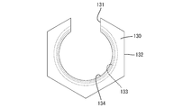
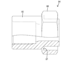
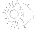
- the relaxation tool 130 is made of a metal material, and is formed in a substantially C shape as a whole as shown in FIG.
- the loosening tool 130 is formed with a communication portion 131 that is cut out so as to communicate from the inner periphery to the outer periphery.
- the opening dimension in the circumferential direction of the communication portion 131 is larger than the outer diameter of the pipe P.
- a relaxation fitting portion 132 having a regular hexagonal shape is formed on the outer periphery of the relaxation tool 130.
- the loose fitting part 132 can be fitted with a general-purpose tool 120 similar to that used for rotating the tightening nut 36.
- a relaxation female screw portion 133 is formed in the front end side region of the inner periphery of the relaxation tool 130.
- the direction of the spiral of the female thread portion for relaxation 133 is a left-hand thread, as is the case with the male thread portion for relaxation 68.
- a restricting abutment portion 134 is formed over the entire circumference at the rear end portion of the inner periphery of the relaxation tool 130 so as to protrude radially inward in a rib shape.
- the inner diameter of the restricting abutment portion 134 is set to be larger than the maximum outer diameter of the first male screw portion 38 and smaller than the outer diameter of the large diameter portion 67.
- the closing valve A has a means for preventing the fastening member 32 from being loosened and detached from the joint body 16 before the pipe P is connected to the pipe joint Ja.
- a separation regulating member 60 is provided.
- the separation regulating member 60 also has a function as a sealing member for regulating the flow of the refrigerant in the pipe joint Ja (insertion space 23).
- the detachment restricting member 60 can be attached to the pipe joint Ja and removed from the pipe joint Ja.
- the detachment restricting member 60 is made of brass, and is formed by integrally forming a cylindrical main body portion 61, a stopper 62, and a third male screw portion 63.
- a regular hexagonal fitting hole 64 opened at the rear end face is formed inside the cylindrical main body 61.
- the outer diameter dimension of the cylindrical main body 61 is smaller than the minimum inner diameter of the ferrule 33 that is not deformed.
- the stopper 62 is located on the outer periphery of the rear end portion of the cylindrical main body 61 and is formed in a flange shape that is concentric with the cylindrical main body 61.
- the outer diameter of the stopper 62 is larger than the outer diameter of the cylindrical main body 61 and the inner diameter of the small diameter portion 47 of the tightening nut 36.
- the third male screw portion 63 is formed on the outer periphery of the front end portion of the cylindrical main body portion 61.
- the direction of the spiral of the third male screw portion 63 and the third female screw portion 28 is the same as that of the first male screw portion 38, the first female screw portion 46, the second male screw portion, and the second female screw portion 37, and is a right-hand screw. Is set to The helical pitch of the third male screw part 63 and the third female screw part 28 is smaller than the helical pitch of the first male screw part 38 and the first female screw part 46.
- a region adjacent to the rear of the third male screw portion 63 in the outer periphery of the cylindrical main body portion 61 is a sealing contact portion 65 formed in a step shape in a continuous form over the entire periphery.
- the outer diameter of the sealing contact portion 65 is larger than the minimum inner diameter size of the front end of the front tapered surface 29 and the outer diameter size of the third male screw portion 63.
- the front end of the ferrule 33 (cylindrical tightening portion 52) slightly contacts the rear taper surface 31 of the joint main body portion 16, but the ferrule 33 is hardly deformed. Further, the abutting portion 42 at the front end of the lock member 11 is positioned so as to face the detection receiving portion 26 of the joint main body portion 16 while being spaced apart rearward.
- the separation regulating member 60 is assembled from the rear in the pipe joint Ja (insertion space 23).
- the cylindrical main body portion 61 is inserted into the insertion space 23, the stopper 62 is picked, and the third male screw portion 63 is screwed into the third female screw portion 28 by hand force without using the general-purpose tool 120.
- the closing valve A in which the assembly of the pipe joint Ja is completed in this way is attached to the outdoor unit B of the heat exchange device. Moreover, although the refrigerant
- the elastic ring 34 When the tightening nut 36 is screwed in, the longitudinal dimension of the holding groove 50 is reduced, the elastic ring 34 is crushed back and forth between the notch portion 45 and the small diameter portion 47, and the inner diameter of the elastic ring 34 is reduced. Thereby, the elastic ring 34 contacts elastically with respect to the outer periphery of the pipe P over the whole periphery. Due to the frictional resistance resulting from this elastic contact, the pipe P is restricted from moving relative to the lock member 11 in the front-rear direction, and as shown in FIG. It is held in the state.
- the general-purpose tool 120 is fitted to the fitting portion 48 of the tightening nut 36 and the outer surface of the housing 15, and the tightening nut 36 is rotated clockwise so as to move forward (tightening direction).
- the fixing member 66a rotates integrally with the tightening nut 36 without being directly applied with a rotational force. .
- the tightening member 32 is screwed in the tightening direction.
- the screwing operation is performed when the abutting portion 42 abuts against the detection receiving portion 26 and the screwing of the tightening member 32 is restricted. Continue until it is done.
- the pressing surface 44 of the fixing member 66a contacts the pressure receiving surface 55 of the ferrule 33, and thereafter, the pressing surface 44 presses the pressure receiving surface 55 in the axial direction. 33 is pushed forward relative to the joint body 16. Along with this, the cylindrical fastening portion 52 is plastically deformed so as to be reduced in diameter by the inclination while sliding on the rear tapered surface 31.
- the first biting portion 56 and the second biting portion 57 bite into the outer periphery of the pipe P like a wedge over the entire circumference, and are relative to each other in the axial direction. Regulate displacement.
- the inner periphery of the ferrule 33 and the outer periphery of the pipe P are sealed in an airtight manner at two places before and after being spaced apart in the axial direction (the length direction of the pipe P). Is locked in a restricted state.
- the front end portion of the outer peripheral surface of the cylindrical tightening portion 52 is in a state of being plastically deformed and tightly adheres to the rear tapered surface 31 over the entire circumference, and the corner edge portion 27 of the joint main body portion 16 is It adheres in an airtight manner to the sealing surface 54 of the ferrule 33 in a state of plastic deformation (collapse deformation) over the entire circumference.
- the space between the outer periphery of the ferrule 33 and the inner periphery of the joint main body portion 16 is hermetically sealed at two positions in the front and rear with a space in the axial direction.
- the above-mentioned airtight biting state and airtight close contact state mean a normal sealing state (normal tightening state) in which the diameter reducing means 22 correctly connects the pipe joint Ja and the pipe P.
- the normal seal state In the normal seal state, the portions that come into contact with each other in the biting portion and the close contact portion are plastically deformed, so that leakage of the refrigerant between the pipe P and the pipe joint Ja is reliably prevented.
- the diameter reducing means 22 is in the normal sealing state immediately before the abutting portion 42 reaches the detection receiving portion 26.
- the diameter-reducing means 22 shifts from an incompletely sealed state (a state in which the cylindrical tightening portion 52 does not bite into the pipe P in an airtight manner) to a normal sealing state, the operator is in a normal tightening state in appearance. You cannot see that it is.
- the operation manual stipulates that tightening of the tightening member 32 (tightening nut 36) is continued while visually checking until the abutting portion 42 abuts against the detection receiving portion 26. Therefore, even a non-skilled person can connect the pipe P so as to be in a normal sealing state by performing the tightening operation of the tightening member 32 according to the operation manual.
- the pipe joint Ja (closing valve A) of the first embodiment has a cylindrical fixing member 66a attached to the joint body 16 by screwing, and the fixing member 66a is screwed by rotating in the tightening direction. Further, by receiving axial pressing force from the fixing member 66a, the ferrule 33 that seals between the inner periphery of the joint main body portion 16 and the outer periphery of the pipe P in an airtight manner, and the fitting portion 48 formed on the outer periphery.
- a fastening nut 36 capable of applying a rotational force in the fastening direction to the fixing member by fitting and rotating the general-purpose tool 120 is provided.
- the fixing member 66a presses the ferrule 33.
- the space between the inner periphery of the joint body 16 and the outer periphery of the pipe P is sealed in an airtight manner, and the flow path 17 and the pipe P are connected.
- the metal bite structure that functions as the locking means 41 includes a bite structure between the corner edge 27 of the joint body 16 and the seal surface 54 of the ferrule 33, a pressure receiving surface 55 of the ferrule 33, and a pressing surface of the fixing member 66a.
- biting structure 44 a biting structure between the front tapered surface 29 of the joint body 16 and the front end of the pipe P, and a first biting part 56 and a second biting part of the outer periphery of the pipe P and the ferrule 33. It is a bite structure between 57. Therefore, even if the rotational force applied to the tightening nut 36 is transmitted to the fixing member 66a, the above-described biting structure reliably prevents the fixing member 66a from being loosened.
- the outer periphery of the fixing member 66a is surrounded by the idly-coverable cover 110a, even if the general-purpose tool 120 is fitted to the outer periphery of the cover 110a and a rotational force in the loosening direction is applied, the cover 110a only rotates freely. Thus, the rotational force of the general-purpose tool 120 is not transmitted to the fixing member 66a. In addition, when the cover 110a is broken by the general-purpose tool 120 and is detached from the fixing member 66a, or when the cover 110a is largely moved backward, the outer periphery of the fixing member 66a is exposed.
- the outer periphery of the fixing member 66 a is configured by a perfectly circular circumferential surface region 40, a perfectly circular relaxation male screw portion 68, and a true circular first male screw portion 38. Therefore, even if the general-purpose tool 120 is directly fitted on the outer periphery of the fixing member 66a to apply a rotational force in the loosening direction, the general-purpose tool 120 slips. In addition to the true circular sliding action, the fixing member 66a cannot be rotated by the loosening prevention means 41 by biting between metals.
- the pipe joint Ja (closing valve A) of the first embodiment regulates the rotation of the fixing member 66a in the loosening direction when the general member 120 is used to apply a rotational force to the fixing member 66a.
- a loosening prevention means 41 for maintaining an airtight seal state by the ferrule 33 is provided. Therefore, even if a rotational force is applied to the fixing member 66a by the general-purpose tool 120 in the state where the pipe P is connected, the fixing member 66a can be rotated in the loosening direction by which the pressing to the ferrule 33 is released by the locking means 41. Be regulated. According to the first embodiment, the reliability of the hermetic sealing performance by the ferrule 33 is excellent.
- the pipe joint Ja (closing valve A) of the first embodiment is a joint body as a means for releasing the lock member 11 and the pipe P from the pipe joint Ja (joint body portion 16) and releasing the hermetic seal state by the ferrule 33.
- a pressure receiving portion 39 that contacts the relaxing tool 130 and restricts further screwing when the working tool 130 is screwed into the loosening male screw portion 68 and rotated in the direction opposite to the fastening direction of the fixing member 66a; Is provided.
- the tightening nut 36 is loosened and removed from the fixing member 66a, and is slid backward.
- the rotational force of the general-purpose tool 120 and the tightening nut 36 is applied to the fixing member 66a, but the fixing member 66a is fixed to the joint body 16 without loosening by the locking means 41.
- the cover 110a is slid to the exposed position to expose the relaxing male screw portion 68, and the relaxing tool 130 is moved to the rear of the fixing member 66a. To wait coaxially.
- the relaxation tool 130 is rotated leftward (opposite to the rotation direction when the fixing member 66a is tightened), the relaxation tool 130 is screwed into the relaxation male screw portion 68 and moved forward, and the restriction abutment portion 134 is moved. Is brought into contact with the pressure receiving portion 39 (see FIG. 8).
- the operation of rotating the relaxation tool 130 may be performed by directly gripping the relaxation tool 130 by hand, or may be performed by fitting the general-purpose tool 120 to the relaxation fitting portion 132.
- the loosening tool 130 in contact with the pressure receiving portion 39 is restricted from further screwing operation, that is, relative rotation with respect to the fixing member 66a and relative movement in the axial direction (forward).
- the general-purpose tool 120 is fitted into the loosening fitting portion 132, and a leftward turning force that exceeds the rotation regulating force by the loosening prevention means 41 is applied to the loosening tool 130.
- the relaxation tool 130 further rotates leftward (in the direction in which the regulating abutment 134 is pressed against the pressure receiving portion 39), and the fixing member 66a is integrated with the relaxation tool 130 in the leftward direction (opposite to the tightening direction). In the loosening direction).
- the fixing member 66a rotates in the loosening direction, the ferrule 33 is released from the pressed state by the fixing member 66a, so that the hermetic seal state by the ferrule 33 is released.
- the airtight performance by the ferrule 33 is not lost even if only the general-purpose tool 120 is used, and the relaxation tool 130 and the general-purpose tool 120 are used in combination when necessary. By doing so, the airtightness by the ferrule 33 can be released.
- the relaxation tool 130 is composed of a single part having a substantially C-shape as a whole, and on the inner periphery of the relaxation tool 130, a relaxation male screw portion 68 is provided. A female thread portion for relaxation 133 that can be screwed is formed.
- the relaxation tool 130 has a form in which a part in the circumferential direction is cut out to allow the outer periphery and the inner periphery to communicate with each other, and a communication part 131 in which the notch dimension is set larger than the outer diameter of the pipe P is formed. Has been. According to this configuration, when the relaxation tool 130 is screwed into the relaxation male screw portion 68, the relaxation tool 130 is relaxed by passing the pipe P through the communication portion 131 without cutting the pipe P. It can arrange
- the pipe joint Ja according to the first embodiment is movable on the outer periphery of the fixing member 66a between a protection position that covers the relaxation male screw portion 68 and an exposed position that exposes the relaxation male screw portion 68.
- a cover 110a is attached. Therefore, in a state where the relaxation tool 130 is not screwed into the relaxation male screw portion 68, the relaxation male screw portion 68 can be protected by the cover 110a.
- the pipe joint Ja (closing valve A) of the first embodiment is provided with an elastic ring 34 as a holding means capable of holding the pipe P in a retained state by coming into contact with the pipe P inserted into the insertion space 23.
- an elastic ring 34 as a holding means capable of holding the pipe P in a retained state by coming into contact with the pipe P inserted into the insertion space 23.
- the pipe P inserted into the insertion space 23 can be held in the retaining state. Therefore, there is no possibility that the pipe P will come out of the insertion space 23 between the time when the pipe P is inserted into the insertion space 23 and the time when the tightening operation of the tightening member 32 is started.
- the elastic ring 34 is disposed at a position facing the insertion space 23 and is not exposed to the outer surface of the pipe joint, the elastic ring 34 is protected from foreign matter interference.
- the fastening member 32 is screwed into the fixing member 66a that is in contact with the ferrule 33 and applies a pressing force, and the fixing member 66a is given a screwing force in the fastening direction, whereby the ferrule is applied to the fixing member 66a.
- a tightening nut 36 for applying a pressing force to the side 33.
- the elastic ring 34 is arranged so as to be sandwiched between the fixing member 66a and the tightening nut 36 in the axial direction, and the diameter of the elastic ring 34 is reduced by screwing the tightening nut 36 in the tightening direction so as to be in close contact with the outer periphery of the pipe P. It is supposed to be.
- the elastic ring 34 is not reduced in diameter before the pipe P is inserted, the frictional resistance at the time of insertion of the pipe P is reduced, so that workability is improved.
- the pipe P After inserting the pipe P, the pipe P can be held in the retaining state by the elastic ring 34 by screwing the tightening nut 36 in the tightening direction.
- the inner circumference of the joint main body portion 16 has a shape that is reduced in diameter toward the front in the insertion direction of the pipe P, and a front tapered surface 29 that abuts the tip of the pipe P that is normally inserted into the insertion space 23.
- the elastic ring 34 is arranged behind the front tapered surface 29 in the insertion direction of the pipe P. According to this configuration, the pipe P that is normally inserted into the insertion space 23 has its tip abutted against the front taper surface 29, and is held in a retaining state by the elastic ring 34. Since the position of contact with the front tapered surface 29 and the holding position by the elastic ring 34 are spaced from each other in the insertion direction of the pipe P, the pipe P is maintained in a stable posture without being inclined with respect to the axis. .
- the closing valve A includes a separation regulating member 60 for regulating the separation of the clamping member 32 from the joint body 16 in a state where the clamping member 32 does not apply a pressing force to the ferrule 33. ing. Therefore, the fastening member 32 does not detach from the joint body 16 even when receiving an external force in the loosening direction. Further, the cylindrical main body 61 of the separation regulating member 60 is accommodated in the insertion space 23 into which the pipe P is inserted. Accordingly, the entry of foreign matter into the insertion space 23 is prevented, and the ferrule 33 is prevented from being damaged by the foreign matter. Further, since the separation regulating member 60 functions as a sealing member that prevents the refrigerant in the flow path 17 from leaking outside through the insertion space 23, the sealing member is provided separately from the separation regulating member 60. Compared to, the number of parts is reduced.
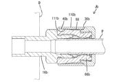
- Example 2> 12 and 13 show a pipe joint Jb of Example 2 of the present invention.
- the pipe joint Jb of the second embodiment is a single-function type joint means attached to the indoor unit D, and is connected to the pipe joint Ja of the closing valve A of the first embodiment through the pipe P.
- the joint main body 16b constituting the pipe joint Jb is connected to the refrigerant flow passage of the indoor unit D.
- the fixing member 66b and the cover 110b constituting the pipe joint Jb are different from those in the first embodiment.
- the fixing member 66b of the second embodiment is such that the outer surface dimension of the circumferential surface region 40b gradually increases toward the front as a means for restricting the cover 110b from moving forward relative to the fixing member 66b. It is formed in a taper shape.
- a tapered circumferential surface region 40b and a tapered positioning surface 111b capable of contacting the surface are formed on the inner peripheral surface of the front end portion of the cover 110b. Further, as a means for restricting the relative displacement of the cover 110b rearward with respect to the fixing member 66b, a stepped receiving portion 36b formed on the outer periphery of the tightening nut 36 is brought into contact with or approaches the cover 110b from the rear. And are facing each other. When the fastening nut 36 is removed from the fixing member 66b in order to remove the pipe P from the pipe joint Jb, the cover 110b is displaced rearward with respect to the fixing member 66b, whereby the loosening male screw portion 68 is exposed.
- action, and an effect, description is abbreviate
- Example 3> 14 and 15 show a pipe joint Jc of Example 3.
- the pipe joint Jc of the third embodiment is also attached to the indoor unit D.
- the fixing member 66c and the cover 110c constituting the pipe joint Jc are different from those in the first embodiment.
- the rear end of the cover 110c is provided between the rear end surface of the large-diameter portion 67c of the fixing member 66c and the stepped receiving portion 36c of the tightening nut 36.
- the circumferential positioning rib 111c formed on the inner periphery of the part is sandwiched.
- Example 4 In FIG. 16, the pipe joint Jd of Example 4 is shown.
- the pipe joint Jd of the fourth embodiment is also attached to the indoor unit D as in the second and third embodiments.
- a relaxation male screw portion 68d is formed over the entire length of the outer periphery of the large diameter portion 67d.
- the cover 110d of the fourth embodiment has the same form as the cover 110c of the third embodiment, and has positioning ribs 110d.
- action, and an effect, description is abbreviate
- Example 5 In FIG. 17, the pipe joint Je of Example 5 is shown.
- the pipe joint Je of the fifth embodiment is also attached to the indoor unit D as in the second to fourth embodiments.
- the fixing member 66e and the cover 110e constituting the pipe joint Je of the fifth embodiment are of the same form as in the first embodiment, but the joint main body portion 16e is different from the first embodiment.
- a front stop portion 26e In the front end portion of the outer peripheral diameter end portion 25e of the joint main body portion 16e of the fifth embodiment, that is, at a position in front of the loosening male screw portion 68, a front stop portion 26e that protrudes in a rib shape along the circumferential direction. Is formed.
- region ahead of the front stop part 26e (expanded diameter part 25e) among the outer periphery of the coupling main-body part 16e is the jig
- Example 6 In FIG. 18, the pipe joint Jf of Example 6 is shown.
- the pipe joint Jf of the sixth embodiment is also attached to the indoor unit D as in the second to fifth embodiments.
- the fixing member 66f and the cover 110f constituting the pipe joint Jf of the sixth embodiment are of the same form as in the first and fifth embodiments, but the joint body 16f is different from the first and fifth embodiments.
- a front stop portion 26f for preventing the cover 110f from moving forward is formed on the outer periphery of the enlarged diameter portion 25f of the joint main body portion 16f of the sixth embodiment.
- the front stop portion 26f is formed at a substantially central position of the enlarged diameter portion 25f in the front-rear direction, that is, at a position in front of the loosening male screw portion 68, and the outer periphery of the enlarged diameter portion 25f is formed in a step shape. .
- a region in front of the front stop portion 26f in the outer periphery of the enlarged diameter portion 25f is a jig fitting portion 140f having a regular hexagonal cross section for fitting a general-purpose jig (not shown).
- the cover 110f is displaced forward so as to cover the region behind the front stop portion 26f of the enlarged diameter portion 25f with respect to the fixing member 66f. Then, when the cover 110f moves forward until it comes into contact with the front stop portion 26f, the loosening male screw portion 68 covered with the cover 110f is exposed.
- action, and an effect, description is abbreviate
- Example 7 In FIG. 19, the pipe joint Jg of Example 7 is shown.
- the pipe joint Jg of the seventh embodiment is applied as a joint means for relaying the pipe P connected to the outdoor unit B of the first embodiment and the pipe P connected to the indoor unit D of the second to sixth embodiments. It is.
- the pipe joint Jg of the seventh embodiment has a joint body portion 16g having an internal passage 17g.
- a jig fitting portion 140g for fitting a general-purpose tool (not shown) is formed on the outer periphery of the joint body portion 16g.
- the joint function part 12 having the same form as that of the first embodiment is assembled to the opening on the upstream end side and the opening on the downstream end side of the joint body part 16g.
- the joint body portion 16g and the pair of joint function portions 12 constitute the pipe joint Jg of the seventh embodiment.
- the pipe P is connected to these joint function parts 12, respectively.
- a pipe joint (not shown) in which the flow path 17g of the joint body 16g is branched into a plurality of parts can be used.
- the connection form of the pipes P in this case, for example, the number of connections of the pipes P on the outdoor unit B side is one, the number of connections of the pipes P on the indoor unit D side is plural, and the pipe joint is for branch piping It can also be used as a joint means.
- action, and an effect, description is abbreviate
- Example 8 In FIG. 20, the pipe joint Jh of Example 8 of this invention is shown.
- the elastic ring 270 is made of rubber or synthetic resin, and the cross-sectional shape thereof is a polygon (pentagon).
- the thickness dimension of the elastic ring 270 (the dimension in the radial direction between the inner peripheral surface and the outer peripheral surface) gradually decreases toward the rear. That is, the cross-sectional shape of the elastic ring 270 is a wedge shape.
- the elastic ring 270 can also be applied when the fixing member 271 and the tightening nut 272 are an integral part.
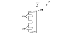
- the elastic ring 273 is made of rubber, synthetic resin, or metal, and has a substantially C shape.
- the elastic ring 273 includes a ring main body portion 274 and a plurality of projecting pieces 275 that cantilever from the ring main body portion 274 forward (that is, in the same direction as the pipe insertion direction).
- the plurality of projecting pieces 275 are arranged at intervals in the circumferential direction, and the projecting direction of the projecting pieces 275 is an oblique direction toward the center of the elastic ring 273.
- the projecting end (front end) of the projecting piece 275 elastically contacts the outer periphery of the pipe, whereby the pipe is held in the retaining state.
- Example 10 In FIG. 22, the pipe joint Jm of Example 10 of this invention is shown.
- a guide groove portion 277 that guides the diameter of the front end portion of the pipe P is formed on the inner periphery of the joint main body portion 276.
- the front end portion of the pipe P that has entered the guide groove portion 277 is plastically deformed in a flare shape, and the front end portion that is expanded in the flare shape is hooked, so that the pipe P is held in a retaining state.
- FIG. 23 shows a pipe joint Jn according to Example 11 of the present invention.
- the pipe joint Jn includes the joint function part 12 having the same structure as that of the first embodiment, but the separation regulating member 370 is different from that of the first embodiment.
- the pipe joint Jn of the second embodiment is a joint means for the closing valve A that is attached to the outdoor unit B as in the first embodiment, or a single-function (no valve function) type joint means that is attached to an indoor unit (not shown). And, it can be applied as a joint means for relaying the pipe P connected to the outdoor unit B and the pipe P connected to the indoor unit.
- the joint body 16 is connected to the refrigerant flow passage of the indoor unit.
- the joint function part 12 is attached to the upstream end and the downstream end of the joint body part 16 respectively.
- the number of pipes P connected on the outdoor unit B side is one, and the number of pipes P connected on the indoor unit side is plural.
- the joint Jn can also be used as a joint means for branch piping.
- the detachment restricting member 370 includes a screw member 371 that is attached to the inner periphery of the joint body 16 by screwing, and an arm member 372 that is attached to the screw member 371.
- a mounting groove 373 is formed on the outer periphery of the rear end portion of the screw-in member 371.
- the arm member 372 includes a substantially C-shaped annular portion 374, a plurality of arm portions 375 extending rearward from the annular portion 373 at intervals in the circumferential direction, and radially outward from the rear end of the arm portion 375.
- the locking portion 376 extends.
- the arm member 372 is assembled to the screw-in member 371 by fitting the annular portion 374 into the mounting groove 733.
- the detachment restricting member 370 When the detachment restricting member 370 is screwed and attached to the third female screw portion 28 of the joint body portion 16, almost the entire screw member 371 and the arm portion 375 are accommodated in the insertion space 23, and the locking portion 376 is inserted in the insertion space 23. It is exposed to the back.
- the locking portion 376 is positioned so as to abut or approach the small diameter portion 47 of the tightening nut 36 from the rear. Even when the tightening member 32 rotates in the loosening direction, the small-diameter portion 47 is locked to the locking portion 376 in a state where the tightening member 32 (lock member 11) is screwed into the joint main body portion 16. Therefore, the fastening member 32 does not come off from the joint body 16.
- FIG. 24 shows a pipe joint Jp of Example 12 of the present invention.
- This pipe joint Jp has the joint function part 12 having the same structure as that of the first embodiment, but the separation regulating member 380 is different from that of the first embodiment.
- the pipe joint Jp of the second embodiment is a joint means for the closing valve A that is attached to the outdoor unit B as in the first embodiment, or a single-function (no valve function) type joint means that is attached to an indoor unit (not shown). And, it can be applied as a joint means for relaying the pipe P connected to the outdoor unit B and the pipe P connected to the indoor unit.
- the joint body 16 is connected to the refrigerant flow passage of the indoor unit.
- the joint function part 12 is assembled to the upstream end and the downstream end of the joint body part 16 respectively.
- the number of pipes P connected on the outdoor unit B side is one, and the number of pipes P connected on the indoor unit side is plural.
- the joint Jp can also be used as a joint means for branch piping.
- the detachment regulating member 380 includes a screw member 381 that is attached to the inner periphery of the joint body 16 by screwing, and a ring member 382 having a larger outer diameter than the screw member 381.
- a mounting groove 383 is formed on the outer periphery of the rear end portion of the screw-in member 381.
- the ring member 382 has a substantially C-shape and is assembled to the screw-in member 381 by fitting in the mounting groove 383.
- the detachment regulating member 380 When the detachment regulating member 380 is screwed and attached to the third female screw portion 28 of the joint main body portion 16, almost the entire portion excluding the rear end portion of the screwed member 381 is accommodated in the insertion space 23, and the ring member 382 is inserted into the insertion space 23. It is exposed to the back.
- the ring member 382 is positioned so as to abut against or approach the small diameter portion 47 of the tightening nut 36 from the rear. Even if the tightening member 32 rotates in the loosening direction, the small-diameter portion 47 is locked to the ring member 82 in a state where the tightening member 32 (lock member 11) is screwed into the joint main body portion 16. Therefore, the fastening member 32 does not come off from the joint body 16.
- ⁇ Reference Example 1> 25 to 33 show the pipe joint Jr of Reference Example 1 of the present invention.
- the pipe joint Jr of the reference example 1 and the pipe joint Ja of the first embodiment are different in the following points.
- the male screw portion 68 for loosening the left screw and the positioning groove 69 are formed, whereas in the fixing member 35 of the pipe joint Jr of the first reference example, The relaxing male screw portion 68 and the positioning groove 69 are not formed.
- the pipe joint Ja according to the first embodiment is provided with a cover 110a that surrounds the fixing member 66a so as to be relatively rotatable, whereas the pipe joint Jr according to the first embodiment has a cover 110a that surrounds the fixing member 35. Is not provided.
- the operation and effect of the present reference example 1 having the above differences is as follows. After the pipe P is connected to the pipe joint Jr (joint function part 12), if the rotational force in the loosening direction is mistakenly applied to the fastening nut 36, the fastening nut 36 moves in the loosening direction as shown in FIG. Although it rotates, the fixing member 35 does not rotate in the loosening direction because the loosening prevention means 41 is provided by biting between metals. Further, even when a general-purpose tool is fitted to the fixing member 35, the outer peripheral surface of the fixing member 35 is rotated to the fixing member 35 by the loosening prevention means 41 by biting between metals in addition to the circumferential surface region 40 having a circular cross section. Power cannot be granted.
- the metal biting structure that functions as the locking means 41 is a biting structure between the corner edge 27 of the joint body 16 and the seal surface 54 of the ferrule 33, and the pressure receiving surface 55 of the ferrule 33.
- the biting structure between the pressing surface 44 of the fixing member 35, the biting structure between the front tapered surface 29 of the joint body 16 and the front end of the pipe P shown in FIG. 29, and the pipe P shown in FIG. This is a biting structure between the outer periphery and the first biting part 56 and the second biting part 57 of the ferrule 33. With these biting structures, loosening of the fixing member 35 is reliably prevented.
- FIG. 34 shows Reference Example 2 of the present invention. Since the outer periphery of the tightening nut 70 is not a regular hexagon but is circular as a whole, the tightening nut 70 cannot be rotated by a general-purpose tool (not shown). On the outer periphery of the tightening nut 70, a plurality of recessed portions 71 are formed at intervals in the circumferential direction. A convex portion 73 of the dedicated tool 72 is fitted into the concave portion 71. When the protrusion 73 is fitted to the recess 71 and the dedicated tool 72 is turned, the tightening nut 70 can be tightened or loosened.
- FIG. 35 shows Reference Example 3 of the present invention. Since the outer periphery of the tightening nut 74 is not a regular hexagonal shape but an oval shape as a whole, the tightening nut 74 cannot be rotated with a general-purpose tool (not shown). On the outer periphery of the tightening nut 74, a plurality of recessed portions 75 spaced apart in the circumferential direction are formed. A convex portion 77 of the dedicated tool 76 is fitted into the concave portion 75. When the convex part 77 is fitted to the concave part 75 and the dedicated tool 76 is turned, the tightening nut 74 can be tightened or loosened.
- a ring-shaped dedicated adapter 78 can be used instead of the dedicated tool 76.
- a convex portion 79 is formed on the inner periphery of the dedicated adapter 78.
- the outer periphery of the dedicated adapter 78 has a regular hexagonal shape.
- the dedicated adapter 78 is assembled to the tightening nut 74 so as to be integrally rotatable, and a general-purpose tool (not shown) is fitted to the outer periphery of the dedicated adapter 78.
- the tightening nut 74 can be tightened or loosened.
- the recess 75 may be formed on the outer periphery of the fixing member (not shown), and the fixing member may be tightened or loosened using the dedicated tool 76 or the dedicated adapter 78.
- FIG. 36 shows a fastening member 80 of Reference Example 4 of the present invention.
- the fastening member 80 is a form in which a fixing member 81 that abuts against a ferrule (not shown) and applies a pressing force, and a fastening nut 82 that is coaxially connected to the rear end of the fixing member 81 are integrally formed. It is.
- the outer periphery of the tightening nut 82 is a regular hexagon. By fitting a general-purpose tool (not shown) to the tightening nut 82, the tightening member 80 can be rotated in the tightening direction.
- a rotational force in the tightening direction is further applied to the tightening nut 82.
- the thin connecting portion 83 that connects the fixing member 81 and the tightening nut 82 is broken, and the tightening nut 82 is detached from the fixing member 81.
- the fastening nut 82 has a form in which a part thereof in the circumferential direction is cut out, and a communication portion (not shown) that connects the inner periphery and the outer periphery of the fastening nut 82 is formed. The clamping nut 82 detached from the pipe can be removed from the pipe (not shown).
- FIG. 37 shows a fastening member 84 of Reference Example 5 of the present invention.
- the tightening member 84 is a form in which a fixing member 85 that abuts on a ferrule (not shown) to apply a pressing force and a tightening nut 86 that is coaxially connected to the fixing member 85 are integrally formed.
- the front end portion of the tightening nut 86 is connected to the outer periphery of the fixing member 85.
- the outer periphery of the tightening nut 86 is a regular hexagon.
- the fastening nut 86 has a form in which a part thereof in the circumferential direction is cut out, and a communication portion (not shown) that connects the inner periphery and the outer periphery of the fastening nut 86 is formed. The fastening nut 86 detached from the pipe can be removed from the pipe (not shown).
- FIG. 38 shows Reference Example 6 of the present invention.
- the outer periphery of the tightening nut 88 has six planes 89 arranged so as to be adjacent to each other at an angle of 120 °, and generally forms a regular hexagon.
- Each plane 89 is formed with a stopper 90 projecting radially outward at one end in the circumferential direction (the rear end in the clockwise direction in FIG. 38).
- the other end portion in the circumferential direction of each plane 89 is connected to the stopper 90 of the plane 89 located adjacent (front in the clockwise direction in FIG. 38) in a flush manner.
- a general-purpose tool 91 having a pair of fitting surfaces 92 parallel to each other is fitted on the outer periphery of the tightening nut 88.
- the upper fitting surface 92 in FIG. 38 is fitted to the upward plane 89 in FIG.
- the lower fitting surface 92 in FIG. 38 is in a state of making a gap with respect to the downward plane 89 in FIG. 38 and abutting the protruding end of the stopper 90 protruding from the downward plane 89.
- FIG. 39 shows Reference Example 7 of the present invention.
- a synthetic resin fastening nut 94 is screwed into the fixing member 93.
- the outer periphery of the tightening nut 94 is a regular hexagon.
- the tightening nut 94 and the fixing member 93 can be integrally rotated in the tightening direction.
- further rotation in the tightening direction to the tightening nut 94 is performed.
- the synthetic resin-made clamping nut 94 is broken and detached from the fixing member 93. Since the outer periphery of the fixing member 93 is circular, the fixing member 93 cannot be loosened with a general-purpose tool.
- FIG. 40 shows Reference Example 8 of the present invention.
- a region between the front end of the second male screw portion 96 and the detection receiving portion 97 in the outer periphery of the joint main body portion 95 has a smaller diameter than the maximum outer diameter of the second male screw portion 96.
- a locking ring 100 having a substantially C shape that can be elastically deformed is attached to the groove portion 99 on the inner periphery of the front end portion of the fixing member 98.
- the minimum inner diameter of the locking ring 100 that is not elastically deformed is smaller than the maximum outer diameter of the second male screw portion 96.
- FIG. 41 shows Reference Example 9 of the present invention.
- the pipe joint C is attached to the indoor unit D.
- the pipe joint C is connected to the pipe joint Ja of the closing valve A according to the first embodiment through the pipe P.
- This pipe joint C has the same joint function part 12 as in the first embodiment, an elastic ring 34 for holding the pipe P on the joint body part before the fastening member 32 is tightened, and after the pipe P is connected. It has locking means 41 for preventing the fixing member 66 from loosening.
- the present invention is not limited to the embodiments described with reference to the above description and drawings.
- the following embodiments are also included in the technical scope of the present invention.
- the second male screw portion and the second female screw portion are right screws
- the relaxation male screw portion and the relaxation female screw portion are left screws.
- Two female screw portions may be a left screw, and a loosening male screw portion and a relaxing female screw portion may be a right screw.
- the relaxation tool is a single part in the first embodiment, the relaxation tool may be a combination of two halves that are independent parts. In this case, the two halves may be connected by a hinge.
- the loosening male screw portion is formed on the outer periphery of the fixing member.
- the outer peripheral portion of the fixing member is formed in a cylindrical shape
- a male screw may be formed on the outer periphery of the relaxation tool.
- the outer periphery of the relaxation tool is formed in a polygonal shape for fitting a general-purpose tool.
- the present invention is not limited to this, and the lever shape protrudes in the radial direction on the outer periphery of the relaxation tool.
- the loosening tool can be screwed into the loosening screw part by grasping the operation part, so that a general-purpose tool becomes unnecessary.
- the cover that covers the relaxation male screw part is idled. However, the cover may not be idled.
- the cover is used as a means for concealing the relaxation male screw portion. However, the relaxation male screw portion may be concealed with a tightening nut.
- the relaxation male screw part is covered with a cover when not in use, but the relaxation male screw part may be always exposed.
- the cross-sectional shape of the fitting portion on the outer periphery of the tightening nut is a regular hexagon, but the cross-sectional shape of the outer periphery of the tightening nut is a regular hexagon if a general-purpose tool can be fitted. It may be a regular polygon other than a square (for example, a regular triangle).
- the tightening nut is screwed into the fixing member and the fixing member is screwed into the joint body. However, the tightening nut may be directly screwed into the joint body. In this case, the tightening nut may not be screwed into the fixing member.
- the material of the joint body (housing), ferrule, fixing member, and tightening nut is made of brass, but at least a part of these members is made of a metal other than brass (for example, aluminum or an aluminum alloy may be used.
- the material of the separation regulating member is brass, but the separation regulating member 60 may be made of a metal other than brass (for example, aluminum or aluminum alloy), may be made of a synthetic resin, or is a metal member. And a synthetic resin member may be combined.
- the helical pitch of the second male screw part and the second female screw part is set larger than the helical pitch of the first male screw part and the first female screw part.
- the relationship may be opposite to that in the first and second embodiments, and both spiral pitches may be the same.
- the helical pitch of the first male screw portion and the first female screw portion is larger than the helical pitch of the third male screw portion and the third female screw portion.
- both the helical pitches may be the same.
- the helical pitch of the second male screw portion and the second female screw portion is larger than the helical pitch of the third male screw portion and the third female screw portion.
- the relationship may be opposite to that in the first embodiment, and both the helical pitches may be the same.
- the pipe joint for the indoor unit has been described.
- the structure of the fixing member and the cover in the second to sixth embodiments is the same as that of the first embodiment.
- the present invention can be applied as a pipe joint to be configured, and can also be applied as a joint means for relay as in the seventh embodiment.
- the holding means (elastic ring) is connected over the entire circumference, but the elastic ring may be C-shaped.
- the holding means (elastic ring) is a separate part from the fixing member and the tightening nut.
- the portion of the holding means that directly contacts the pipe is a tightening nut or a fixing nut. May be formed integrally.
- the holding means (elastic ring) is disposed at a position corresponding to the tightening member in the pipe insertion direction. However, the elastic ring is more forward or rearward than the tightening member in the pipe insertion direction. You may arrange
- the pipe may be held by forming a groove on the inner periphery of the joint body, forming a dimple on the outer periphery of the pipe, and locking the dimple on the groove.
- an elastic ring may be attached to a groove formed on the inner periphery of the joint body, and the pipe may be held in a retaining state by the elastic ring.
- the tightening member is composed of two parts including the tightening nut and the fixing member.
- the tightening member may be a single part.
- the fastening member is composed of two parts of the fastening nut and the fixing member, and when the ferrule is plastically deformed into the sealed state, the tool is fitted to the fastening nut and tightened.
- a tool may be fitted to the fixing member and tightened.
- the tightening nut may not have a tightening function, but may have only a function of deforming the holding means (elastic ring) by reducing the diameter.
- the outer periphery of the tightening nut is not limited to a regular hexagon, but a shape such as a knurled or projecting knob is easily rotated by hand. Good.
- the holding means (elastic ring) is made of rubber, but the holding means may be made of synthetic resin or metal.
- the holding by the holding means (elastic ring) is realized using frictional resistance.
- the pipe may be held by biting the holding means into the pipe.
- the tightening nut comes into contact with the fixing member.
- the material of the sealing member is brass.
- the sealing member may be made of a metal other than brass (for example, aluminum or aluminum alloy), may be made of a synthetic resin, A combination with a synthetic resin member may be used.
- the pipe joints Jh, Jk, Jm of the above-described eighth, ninth, and tenth are used for relaying joint means connected to an indoor unit such as the second embodiment TO6 and pipes such as the seventh embodiment. It can be applied as a joint means.
- a ... Closing valve B Outdoor unit (heat exchanger) C, Ja, Jb, Jc, Jd, Je, Jf, Jg, Jh, Jk, Jm, Jr ... Pipe fitting D ... Indoor unit (heat exchanger) P ... pipe 15 ... housing 16, 16b, 16e, 16f, 16g ... joint body 17, 17g ... flow path 20 ... first valve body (valve body) 21 ... Second valve element (valve element) 23 ... Insertion space 29 ... Front taper surface (taper surface) 32 ... Fastening member 33 ... Ferrule 34 ... Elastic ring (holding means) 35, 66a, 66b, 66c, 66d, 66e, 66f ...
Landscapes
- Engineering & Computer Science (AREA)
- General Engineering & Computer Science (AREA)
- Mechanical Engineering (AREA)
- Physics & Mathematics (AREA)
- Thermal Sciences (AREA)
- Joints With Pressure Members (AREA)
- Quick-Acting Or Multi-Walled Pipe Joints (AREA)
Priority Applications (2)
| Application Number | Priority Date | Filing Date | Title |
|---|---|---|---|
| ES13780867.1T ES2646224T3 (es) | 2012-04-27 | 2013-04-26 | Junta de tubería, válvula de cierre y herramienta de liberación |
| EP13780867.1A EP2843284B1 (fr) | 2012-04-27 | 2013-04-26 | Raccord de tuyau, robinet de fermeture et outil de desserrage |
Applications Claiming Priority (12)
| Application Number | Priority Date | Filing Date | Title |
|---|---|---|---|
| JP2012-103673 | 2012-04-27 | ||
| JP2012103669 | 2012-04-27 | ||
| JP2012-103669 | 2012-04-27 | ||
| JP2012-103676 | 2012-04-27 | ||
| JP2012103676 | 2012-04-27 | ||
| JP2012103673 | 2012-04-27 | ||
| JP2013-057566 | 2013-03-21 | ||
| JP2013057573A JP5395971B2 (ja) | 2012-04-27 | 2013-03-21 | 管継手及び閉鎖バルブ |
| JP2013-057571 | 2013-03-21 | ||
| JP2013-057573 | 2013-03-21 | ||
| JP2013057571A JP5395970B2 (ja) | 2012-04-27 | 2013-03-21 | 管継手及び閉鎖バルブ |
| JP2013057566A JP5329000B1 (ja) | 2012-04-27 | 2013-03-21 | 管継手、閉鎖バルブ及び弛緩用工具 |
Publications (1)
| Publication Number | Publication Date |
|---|---|
| WO2013162005A1 true WO2013162005A1 (fr) | 2013-10-31 |
Family
ID=52440972
Family Applications (2)
| Application Number | Title | Priority Date | Filing Date |
|---|---|---|---|
| PCT/JP2013/062415 Ceased WO2013162005A1 (fr) | 2012-04-27 | 2013-04-26 | Raccord de tuyau, robinet de fermeture et outil de desserrage |
| PCT/JP2013/062416 Ceased WO2013162006A1 (fr) | 2012-04-27 | 2013-04-26 | Raccord de tuyau et robinet de fermeture |
Family Applications After (1)
| Application Number | Title | Priority Date | Filing Date |
|---|---|---|---|
| PCT/JP2013/062416 Ceased WO2013162006A1 (fr) | 2012-04-27 | 2013-04-26 | Raccord de tuyau et robinet de fermeture |
Country Status (3)
| Country | Link |
|---|---|
| EP (2) | EP2843285B1 (fr) |
| ES (2) | ES2645624T3 (fr) |
| WO (2) | WO2013162005A1 (fr) |
Cited By (1)
| Publication number | Priority date | Publication date | Assignee | Title |
|---|---|---|---|---|
| CN114215974A (zh) * | 2021-12-24 | 2022-03-22 | 南京铖联激光科技有限公司 | 一种3d打印用具有提醒功能的保护气装置 |
Families Citing this family (6)
| Publication number | Priority date | Publication date | Assignee | Title |
|---|---|---|---|---|
| CN105757367B (zh) * | 2016-05-04 | 2018-08-17 | 天津创辉帮络克管道联接技术有限公司 | 一种卡套接头装置 |
| CN107893885A (zh) * | 2017-11-27 | 2018-04-10 | 荔浦县冠升塑料制品厂 | 一种管材连接件 |
| CN107763334A (zh) * | 2017-11-27 | 2018-03-06 | 荔浦县冠升塑料制品厂 | 一种水管连接件 |
| US11396963B2 (en) | 2018-01-29 | 2022-07-26 | Brian B. Scott | Device for making plumbing connections and a method of use thereof |
| WO2022251078A1 (fr) * | 2021-05-25 | 2022-12-01 | Kim Brian B | Raccord de tuyau permettant un verrouillage facile avec un couple approprié |
| CN119244845B (zh) * | 2024-11-13 | 2025-11-04 | 国网福建省电力有限公司 | 一种新型变电站sf6电气设备充气装置及其使用方法 |
Citations (4)
| Publication number | Priority date | Publication date | Assignee | Title |
|---|---|---|---|---|
| JP2001108170A (ja) * | 1999-08-04 | 2001-04-20 | Nasuko Fitting Kk | 管継手 |
| JP2003232474A (ja) * | 2002-02-08 | 2003-08-22 | Nasco Fitting Kk | 管継手 |
| JP2005325872A (ja) | 2004-05-12 | 2005-11-24 | Nasco Fitting Kk | 熱交換装置のパイプ接続構造、熱交換装置用操作バルブ、熱交換装置用管継手、熱交換装置用操作バルブ構成体、熱交換装置用操作バルブの操作部材、熱交換装置用管継手構成体及び熱交換装置用管継手の操作部材 |
| JP2010190325A (ja) * | 2009-02-18 | 2010-09-02 | Daikin Ind Ltd | 管接続構造、締結弛緩工具、弁、管継手及び冷凍装置 |
Family Cites Families (12)
| Publication number | Priority date | Publication date | Assignee | Title |
|---|---|---|---|---|
| BE460074A (fr) * | ||||
| US1927464A (en) * | 1930-08-04 | 1933-09-19 | Imp Brass Mfg Co | Compression coupling |
| DE1214489B (de) * | 1960-04-20 | 1966-04-14 | Donald Brown Brownall Ltd | Rohrkupplung |
| GB926201A (en) * | 1961-01-24 | 1963-05-15 | British Ermeto Corp Ltd | Improvements in pipe couplings |
| JPS5663Y2 (fr) * | 1976-11-11 | 1981-01-06 | ||
| JP3939311B2 (ja) * | 2004-05-25 | 2007-07-04 | ナスコフィッティング株式会社 | 管継手 |
| US7353840B1 (en) * | 2006-03-16 | 2008-04-08 | Andrew Price Deinken | Split nut for outlet box installation |
| JP2007292128A (ja) * | 2006-04-21 | 2007-11-08 | Daikin Ind Ltd | 管継手用結合部材 |
| JP4124257B2 (ja) * | 2006-12-12 | 2008-07-23 | ダイキン工業株式会社 | 管継手 |
| JP4144651B2 (ja) * | 2006-12-27 | 2008-09-03 | ダイキン工業株式会社 | 管継手、冷凍装置及びヒートポンプ式温水装置 |
| DE102008053380A1 (de) * | 2007-11-15 | 2009-05-20 | Luk Lamellen Und Kupplungsbau Beteiligungs Kg | Verbindung |
| JP2010025294A (ja) * | 2008-07-23 | 2010-02-04 | Daikin Ind Ltd | 食い込み式管接続構造、弁、食い込み式管継手及び冷凍装置 |
-
2013
- 2013-04-26 ES ES13781099.0T patent/ES2645624T3/es active Active
- 2013-04-26 WO PCT/JP2013/062415 patent/WO2013162005A1/fr not_active Ceased
- 2013-04-26 EP EP13781099.0A patent/EP2843285B1/fr not_active Not-in-force
- 2013-04-26 WO PCT/JP2013/062416 patent/WO2013162006A1/fr not_active Ceased
- 2013-04-26 ES ES13780867.1T patent/ES2646224T3/es active Active
- 2013-04-26 EP EP13780867.1A patent/EP2843284B1/fr not_active Not-in-force
Patent Citations (4)
| Publication number | Priority date | Publication date | Assignee | Title |
|---|---|---|---|---|
| JP2001108170A (ja) * | 1999-08-04 | 2001-04-20 | Nasuko Fitting Kk | 管継手 |
| JP2003232474A (ja) * | 2002-02-08 | 2003-08-22 | Nasco Fitting Kk | 管継手 |
| JP2005325872A (ja) | 2004-05-12 | 2005-11-24 | Nasco Fitting Kk | 熱交換装置のパイプ接続構造、熱交換装置用操作バルブ、熱交換装置用管継手、熱交換装置用操作バルブ構成体、熱交換装置用操作バルブの操作部材、熱交換装置用管継手構成体及び熱交換装置用管継手の操作部材 |
| JP2010190325A (ja) * | 2009-02-18 | 2010-09-02 | Daikin Ind Ltd | 管接続構造、締結弛緩工具、弁、管継手及び冷凍装置 |
Cited By (1)
| Publication number | Priority date | Publication date | Assignee | Title |
|---|---|---|---|---|
| CN114215974A (zh) * | 2021-12-24 | 2022-03-22 | 南京铖联激光科技有限公司 | 一种3d打印用具有提醒功能的保护气装置 |
Also Published As
| Publication number | Publication date |
|---|---|
| EP2843284A1 (fr) | 2015-03-04 |
| ES2645624T3 (es) | 2017-12-07 |
| EP2843285A1 (fr) | 2015-03-04 |
| EP2843285A4 (fr) | 2015-12-16 |
| WO2013162006A1 (fr) | 2013-10-31 |
| EP2843285B1 (fr) | 2017-09-13 |
| EP2843284A4 (fr) | 2015-12-23 |
| ES2646224T3 (es) | 2017-12-12 |
| EP2843284B1 (fr) | 2017-09-13 |
Similar Documents
| Publication | Publication Date | Title |
|---|---|---|
| JP5329000B1 (ja) | 管継手、閉鎖バルブ及び弛緩用工具 | |
| WO2013162005A1 (fr) | Raccord de tuyau, robinet de fermeture et outil de desserrage | |
| JP4866968B1 (ja) | 閉鎖バルブ | |
| JP5012118B2 (ja) | 食い込み式管継手、冷凍装置及び温水装置 | |
| JP3600764B2 (ja) | 管継手 | |
| JP3939311B2 (ja) | 管継手 | |
| JP4145183B2 (ja) | 管継手 | |
| JP2003232474A (ja) | 管継手 | |
| JP2011127647A (ja) | 樹脂管用ワンタッチ継手 | |
| JP5395971B2 (ja) | 管継手及び閉鎖バルブ | |
| WO2010010885A1 (fr) | Structure de raccordement de tuyau de type morsure, valve mettant en oeuvre cette structure de raccordement de tuyau de type morsure, raccord de tuyau de type morsure et dispositif de congélation | |
| JP5395970B2 (ja) | 管継手及び閉鎖バルブ | |
| JP2005325872A (ja) | 熱交換装置のパイプ接続構造、熱交換装置用操作バルブ、熱交換装置用管継手、熱交換装置用操作バルブ構成体、熱交換装置用操作バルブの操作部材、熱交換装置用管継手構成体及び熱交換装置用管継手の操作部材 | |
| JP2021131099A (ja) | 火無し継手における気密試験用プラグ取付構造、火無し継手、及び気密試験用プラグ | |
| JP4193105B2 (ja) | 配管継手の止水栓ハンドル | |
| JP2008144866A (ja) | 管継手とその管継手を用いた管の接続構造および接続方法 | |
| JP4194026B2 (ja) | 弁装置 | |
| JP2007162852A (ja) | 管継手 | |
| JP2002340250A (ja) | 金属管用メカニカル式管継手 | |
| JP4810267B2 (ja) | 管継手 | |
| JP5726634B2 (ja) | 継ぎ手 | |
| JP4568630B2 (ja) | 管継手 | |
| JP2007170464A (ja) | 配管の連結部の保護具 | |
| JP4737174B2 (ja) | 管接続構造、弁、管継手及び冷凍装置 | |
| JP2004176896A (ja) | 配管継手及びその施工方法 |
Legal Events
| Date | Code | Title | Description |
|---|---|---|---|
| 121 | Ep: the epo has been informed by wipo that ep was designated in this application |
Ref document number: 13780867 Country of ref document: EP Kind code of ref document: A1 |
|
| NENP | Non-entry into the national phase |
Ref country code: DE |
|
| REEP | Request for entry into the european phase |
Ref document number: 2013780867 Country of ref document: EP |
|
| WWE | Wipo information: entry into national phase |
Ref document number: 2013780867 Country of ref document: EP |