WO2013176166A1 - Système de rétroviseur de véhicule et véhicule pourvu de ce système - Google Patents
Système de rétroviseur de véhicule et véhicule pourvu de ce système Download PDFInfo
- Publication number
- WO2013176166A1 WO2013176166A1 PCT/JP2013/064180 JP2013064180W WO2013176166A1 WO 2013176166 A1 WO2013176166 A1 WO 2013176166A1 JP 2013064180 W JP2013064180 W JP 2013064180W WO 2013176166 A1 WO2013176166 A1 WO 2013176166A1
- Authority
- WO
- WIPO (PCT)
- Prior art keywords
- vehicle
- image
- display device
- lever member
- display screen
- Prior art date
- Legal status (The legal status is an assumption and is not a legal conclusion. Google has not performed a legal analysis and makes no representation as to the accuracy of the status listed.)
- Ceased
Links
Images




Classifications
-
- B—PERFORMING OPERATIONS; TRANSPORTING
- B60—VEHICLES IN GENERAL
- B60R—VEHICLES, VEHICLE FITTINGS, OR VEHICLE PARTS, NOT OTHERWISE PROVIDED FOR
- B60R1/00—Optical viewing arrangements; Real-time viewing arrangements for drivers or passengers using optical image capturing systems, e.g. cameras or video systems specially adapted for use in or on vehicles
- B60R1/20—Real-time viewing arrangements for drivers or passengers using optical image capturing systems, e.g. cameras or video systems specially adapted for use in or on vehicles
- B60R1/22—Real-time viewing arrangements for drivers or passengers using optical image capturing systems, e.g. cameras or video systems specially adapted for use in or on vehicles for viewing an area outside the vehicle, e.g. the exterior of the vehicle
- B60R1/23—Real-time viewing arrangements for drivers or passengers using optical image capturing systems, e.g. cameras or video systems specially adapted for use in or on vehicles for viewing an area outside the vehicle, e.g. the exterior of the vehicle with a predetermined field of view
- B60R1/26—Real-time viewing arrangements for drivers or passengers using optical image capturing systems, e.g. cameras or video systems specially adapted for use in or on vehicles for viewing an area outside the vehicle, e.g. the exterior of the vehicle with a predetermined field of view to the rear of the vehicle
-
- B—PERFORMING OPERATIONS; TRANSPORTING
- B60—VEHICLES IN GENERAL
- B60R—VEHICLES, VEHICLE FITTINGS, OR VEHICLE PARTS, NOT OTHERWISE PROVIDED FOR
- B60R1/00—Optical viewing arrangements; Real-time viewing arrangements for drivers or passengers using optical image capturing systems, e.g. cameras or video systems specially adapted for use in or on vehicles
- B60R1/12—Mirror assemblies combined with other articles, e.g. clocks
-
- B—PERFORMING OPERATIONS; TRANSPORTING
- B60—VEHICLES IN GENERAL
- B60R—VEHICLES, VEHICLE FITTINGS, OR VEHICLE PARTS, NOT OTHERWISE PROVIDED FOR
- B60R1/00—Optical viewing arrangements; Real-time viewing arrangements for drivers or passengers using optical image capturing systems, e.g. cameras or video systems specially adapted for use in or on vehicles
- B60R1/02—Rear-view mirror arrangements
-
- B—PERFORMING OPERATIONS; TRANSPORTING
- B60—VEHICLES IN GENERAL
- B60R—VEHICLES, VEHICLE FITTINGS, OR VEHICLE PARTS, NOT OTHERWISE PROVIDED FOR
- B60R1/00—Optical viewing arrangements; Real-time viewing arrangements for drivers or passengers using optical image capturing systems, e.g. cameras or video systems specially adapted for use in or on vehicles
- B60R1/02—Rear-view mirror arrangements
- B60R1/04—Rear-view mirror arrangements mounted inside vehicle
-
- B—PERFORMING OPERATIONS; TRANSPORTING
- B60—VEHICLES IN GENERAL
- B60R—VEHICLES, VEHICLE FITTINGS, OR VEHICLE PARTS, NOT OTHERWISE PROVIDED FOR
- B60R1/00—Optical viewing arrangements; Real-time viewing arrangements for drivers or passengers using optical image capturing systems, e.g. cameras or video systems specially adapted for use in or on vehicles
- B60R1/12—Mirror assemblies combined with other articles, e.g. clocks
- B60R2001/1253—Mirror assemblies combined with other articles, e.g. clocks with cameras, video cameras or video screens
-
- B—PERFORMING OPERATIONS; TRANSPORTING
- B60—VEHICLES IN GENERAL
- B60R—VEHICLES, VEHICLE FITTINGS, OR VEHICLE PARTS, NOT OTHERWISE PROVIDED FOR
- B60R2300/00—Details of viewing arrangements using cameras and displays, specially adapted for use in a vehicle
- B60R2300/70—Details of viewing arrangements using cameras and displays, specially adapted for use in a vehicle characterised by an event-triggered choice to display a specific image among a selection of captured images
-
- B—PERFORMING OPERATIONS; TRANSPORTING
- B60—VEHICLES IN GENERAL
- B60R—VEHICLES, VEHICLE FITTINGS, OR VEHICLE PARTS, NOT OTHERWISE PROVIDED FOR
- B60R2300/00—Details of viewing arrangements using cameras and displays, specially adapted for use in a vehicle
- B60R2300/80—Details of viewing arrangements using cameras and displays, specially adapted for use in a vehicle characterised by the intended use of the viewing arrangement
- B60R2300/802—Details of viewing arrangements using cameras and displays, specially adapted for use in a vehicle characterised by the intended use of the viewing arrangement for monitoring and displaying vehicle exterior blind spot views
- B60R2300/8026—Details of viewing arrangements using cameras and displays, specially adapted for use in a vehicle characterised by the intended use of the viewing arrangement for monitoring and displaying vehicle exterior blind spot views in addition to a rear-view mirror system
-
- H—ELECTRICITY
- H04—ELECTRIC COMMUNICATION TECHNIQUE
- H04N—PICTORIAL COMMUNICATION, e.g. TELEVISION
- H04N7/00—Television systems
- H04N7/18—Closed-circuit television [CCTV] systems, i.e. systems in which the video signal is not broadcast
Definitions
- the present invention relates to a vehicle inner mirror system and a vehicle including the vehicle inner mirror system.
- a vehicle inner mirror system is provided with a liquid crystal display device inside a vehicle mirror body, and an image captured by a vehicle-mounted camera is displayed on the liquid crystal display device and provided on the front surface of the vehicle mirror body.
- the thing of the structure made visible to a driver through a half mirror is known (for example, refer patent document 1).
- the power source of the liquid crystal display device and the power source of the in-vehicle camera are turned on / off according to the tilting posture of the vehicle mirror body.
- smear occurs and it is difficult for the driver to view the image when the image is displayed on the liquid crystal display screen of the liquid crystal display device.
- the power of the liquid crystal display device is automatically turned off, and the vehicle mirror body is changed to a posture in which the rear of the vehicle reflected in the half mirror can be seen. It is desirable to have a configuration.
- the present invention has been made in view of the above circumstances, and the object of the present invention is the attitude of the vehicle mirror body when the driver sees the rear of the vehicle reflected in the half mirror and the display screen of the display device.
- the display device is turned on / off in conjunction with the change in the attitude of the vehicle mirror body
- An object of the present invention is to provide an inner mirror system for a vehicle having a configuration and a vehicle having the inner mirror system for a vehicle.
- An inner mirror system for a vehicle includes a display device provided with a signal processing unit that constructs an image from an image signal output from an image receiving unit of a vehicle-mounted camera and displays the image on a display screen, and the display device is provided inside.
- a built-in mirror body for a vehicle, an operation lever member, and a power switch are provided.
- the attitude of the vehicle mirror body is changed between the attitude when the driver sees the rear of the vehicle reflected in the half mirror and the attitude when the driver sees the image displayed on the display screen of the display device.
- the operation lever member is used to change the attitude of the vehicle mirror body, and the power switch turns on and off the display device in conjunction with the operation of the operation lever member.
- the attitude of the vehicle mirror body when the driver sees the rear of the vehicle reflected in the half mirror and the attitude of the vehicle mirror body when viewing the image displayed on the display screen of the display device,
- the display device can be turned on and off in conjunction with the change in the attitude of the vehicle mirror body.
- FIG. 1 is a plan view of a vehicle equipped with an inner mirror system for a vehicle according to the present invention viewed from above.
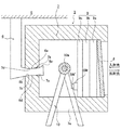
- FIG. 2 is a schematic diagram illustrating a schematic configuration of the vehicle mirror main body illustrated in FIG. 1, and is a diagram illustrating a posture of the vehicle mirror main body when the driver looks at the rear of the vehicle reflected in the half mirror.
- FIG. 3 is a schematic diagram showing a schematic configuration of the vehicle mirror main body shown in FIG. 1, and shows a posture of the vehicle mirror main body when the driver views an image displayed on the liquid crystal display screen of the liquid crystal display device.
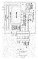
- FIG. FIG. 4 is a block diagram showing a circuit configuration of the liquid crystal display device according to Embodiment 1 of the vehicle inner mirror system according to the present invention.
- FIG. 1 is a plan view of a vehicle equipped with an inner mirror system for a vehicle according to the present invention viewed from above.
- FIG. 2 is a schematic diagram illustrating a schematic configuration of the vehicle mirror main body illustrated in FIG. 1, and is
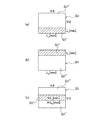
- FIG. 5 is a diagram for explaining a problem caused by a difference between the aspect ratio of the image constructed by the image signal output from the image receiving unit shown in FIG. 4 and the aspect ratio of the liquid crystal display screen shown in FIGS.
- (a) is explanatory drawing explaining the aspect-ratio of the image constructed
- (b) is the aspect of the liquid crystal display screen shown in FIG. 2
- FIG. 4C is an explanatory diagram illustrating a problem when an image is displayed on a liquid crystal display screen using an image signal output from the image receiving unit as it is
- FIG. 6 is an explanatory diagram conceptually showing the conversion of the aspect ratio, and (a) can be seen during driving among the images constructed by the image signal output from the image receiving unit of the in-vehicle camera. It is explanatory drawing at the time of having decided to cut an unnecessary upper image part and performing aspect-ratio conversion, (b) is driving
- FIG. 6 is an explanatory diagram when the aspect ratio conversion is performed by cutting out the upper and lower image portions that are unnecessary to be seen during driving.
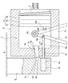
- FIG. 7 is an explanatory diagram of the vehicle inner mirror system according to the second embodiment of the present invention, and shows the posture of the vehicle mirror body when the driver looks at the rear of the vehicle as reflected in the half mirror.
- FIG. 8 is a view showing the attitude of the vehicle mirror body when the driver sees the image displayed on the liquid crystal display screen of the liquid crystal display device by tilting the vehicle mirror body shown in FIG. 7.
- FIG. 9 is a block diagram showing a circuit configuration of a liquid crystal display device according to Embodiment 2 of the vehicle inner mirror system according to the present invention.
- FIG. 1 is a plan view of a vehicle provided with the vehicle inner mirror system according to the present invention as viewed from above.
- reference numeral 1 is a vehicle
- reference numeral 2 is a vehicle-mounted camera
- reference numeral 3 is a vehicle mirror body
- reference numeral 4 is a driver.
- the in-vehicle camera 2 is installed in the vehicle 1 so that a subject behind the vehicle can be imaged.
- the vehicle mirror body 3 is supported in front of the driver 4 and at an appropriate location on the ceiling 5 via a support arm member described later.
- the ceiling 5 is provided with a support arm member 6 extending vertically downward.
- the support arm member 6 has a support portion 6a extending in the horizontal direction.
- Tapered stopper portions 6b and 6c are formed at the front end portion and the rear end portion of the support portion 6a.
- a curved portion 6d having a predetermined curvature is formed between the stopper portion 6b and the stopper portion 6c of the support portion 6a.
- the vehicle mirror body 3 has a housing 7 extending in the lateral direction (horizontal direction).
- a fitting hole 7 a is formed in the rear wall of the housing 7.
- the fitting hole 7a includes fitting holes 7b and 7c corresponding to the shape of the stopper portion 6b of the support portion 6a, and a fitting hole 7d having a curvature corresponding to the curved portion 6d.
- the support portion 6a and the fitting hole 7a are fitted with an appropriate frictional force, and the frictional force is such that the posture of the vehicle mirror main body 3 does not change during vehicle body vibration or the like.
- FIGS 2 and 3 schematically show the support of the vehicle mirror body 3 to the support arm member 6, and the support structure is not limited to this, and the vehicle mirror is not limited to this.
- the assembly of the main body 3 to the support portion 6a can be appropriately devised.
- a liquid crystal display device 9 as a display device is provided in the vicinity of the half mirror 8.
- the liquid crystal display device 9 is unitized.
- Reference numeral 9a indicates a liquid crystal display screen
- reference numeral 9b indicates a backlight illumination section
- reference numeral 9c indicates an electric circuit board section. The circuit configuration of the liquid crystal display device 9 will be described later.
- the aspect ratio between the horizontal width and the vertical width of the casing 7 corresponds to the aspect ratio of the liquid crystal display screen 9 a of the liquid crystal display device 9 in a one-to-one correspondence. There is also a one-to-one correspondence between the aspect ratio of the width and the vertical width.
- the half mirror 8 is used to transmit image display light from the liquid crystal display screen 9a of the liquid crystal display device 9 and to allow the driver 4 to visually recognize the rear of the vehicle.
- An operation lever member 10 for manual operation is provided inside the housing 7.
- the operation lever member 10 can be rotated in the front-rear direction about the rotation shaft 10a.
- a long hole 7 e extending in the front-rear direction is formed in the lower wall of the housing 7.
- the operation lever member 10 extends downward, and a lower end portion thereof is exposed to the outside of the housing 7 through the long hole 7e.
- the operating lever member 10 is slidably contacted with the peripheral wall of the elongated hole 7e with an appropriate frictional force, and the operating lever member 10 has its posture at the rotational operation position by the frictional force due to the peripheral wall of the elongated hole 7e. Retained.
- FIG. 2 shows the tilting posture of the vehicle mirror body 3 when the driver 4 looks at the rear of the vehicle reflected in the half mirror 8.
- FIG. 3 shows an image in which the driver 4 is displayed on the liquid crystal display screen 9a. 2 shows the tilting posture of the vehicle mirror body 3 when viewing through the half mirror 8. At this time, the ceiling 5 is reflected in the half mirror 8.
- the housing 7 When the driver 4 grips the operation lever member 10 and operates the operation lever member 10 in a direction approaching the driver 4, the housing 7 is moved along the curved portion 6d of the support portion 6a.
- the mirror body 3 is shown in FIG. 3 when the driver 4 views the image displayed on the liquid crystal display screen 9a from the posture shown in FIG. 2 when the driver 4 looks at the rear of the vehicle reflected in the half mirror 8. In this state, the posture is maintained.
- the half mirror 8 is disposed on the housing 7 at a slightly oblique angle with respect to the liquid crystal display screen 9a, so that when the vehicle mirror body 3 is held in the tilting posture shown in FIG.
- the reflected light (disturbance light) that has been reflected is directed toward the driver 4.
- the liquid crystal display device 9 includes a signal processing unit 11 that processes an image signal output from the image receiving unit 2a of the in-vehicle camera 2 and displays the image signal on the liquid crystal display screen 9a, a power supply unit 12,
- the image adjustment menu switch 14, a connector unit 15, a backlight illumination unit (LED illumination unit) 16, and an LCD on / off switch SW as a power switch are roughly configured.
- Each of these electric circuit components is disposed on the electric circuit board portion 9c.
- a known imaging device such as a CCD is used for the image receiving portion 2a.
- an AC power supply terminal ACC On the input side of the connector section 15, an AC power supply terminal ACC, a ground terminal GND, an ILL terminal, a power supply + terminal, a power supply ⁇ terminal, an imaging signal input terminal +, and an imaging signal ⁇ input terminal are provided.
- the ILL terminal, the power supply + terminal, and the power supply ⁇ terminal are electrically connected to the in-vehicle camera 2 via a power supply line (not shown), and the imaging signal input terminal + and the imaging signal ⁇ input terminal are signals. It is electrically connected to the image receiving unit 2a of the in-vehicle camera 2 through the system SL.
- the power supply unit 12 includes a camera power supply unit 12a and a backlight power supply unit 12b.
- the LCD on / off switch SW is provided facing the rotation area of the operation lever member 10 as shown in FIGS.
- the LCD on / off switch SW has an actuator part SW ′, which is turned on / off in conjunction with the operation of the operation lever member 10.
- the operation lever member 10 When the driver 4 sees the rear of the vehicle reflected on the half mirror 8, as shown in FIG. 2, the operation lever member 10 is separated from the actuator section SW ', and the image of the driver 4 reflected on the liquid crystal display screen 9a As shown in FIG. 3, the operation lever member 10 is brought into contact with the actuator portion SW ′ as shown in FIG.
- the LCD on / off switch SW When the LCD on / off switch SW is turned on, a voltage is applied from the AC power supply terminal ACC to the power supply unit 12, and power is supplied from the power supply unit 12 to the in-vehicle camera 2 and the backlight illumination unit 16, thereby the backlight.
- the illumination unit 16 is turned on and the vehicle-mounted camera 2 is turned on.
- an image signal from the image receiving unit 2 a is input to the image signal cutout unit 17 via the connector unit 15.
- the function of the image signal cutout unit 17 will be described later.
- the image signal output from the image receiving unit 2 a is an analog signal, but is converted into a digital signal by a known AD / conversion circuit (not shown) in the in-vehicle camera 2, and is directed to the image signal cutting unit 17. Is output.
- the image signal cutout unit 17 outputs the image signal to the signal processing unit 11, and the signal processing unit 11 performs predetermined processing on the input image signal and outputs it to the liquid crystal display screen 9a.
- the brightness, hue, chromaticity, etc. of the image on the liquid crystal display screen 9a can be adjusted by the image adjustment menu switch 14.
- Known configurations can be used for the signal processing unit 11, the power supply unit 12, the image adjustment menu switch 14, the connector unit 15, the backlight illumination unit 16, and the LCD on / off switch SW.
- the image signal cutout unit 17 cuts out an image signal corresponding to an image portion unnecessary for the operation of the driver 4 from the image constructed by the image signal output from the image receiving unit 2a of the in-vehicle camera 2, and the signal processing unit 11 It plays a role to output.
- the image signal cutout unit 17 receives the image signal output from the image receiving unit 2a of the in-vehicle camera 2 and the vertical direction and the horizontal direction among images constructed by the image signal output from the image receiving unit 2a. Are converted to the aspect ratio of the liquid crystal display screen 9a and output to the signal processing unit 11 to be configured.
- the signal processing unit 11 constructs an image having an aspect ratio corresponding to the aspect ratio of the liquid crystal display screen 9a by the remaining image signal excluding the image signal cut out by the image signal cutting unit 17.
- the aspect ratio between the vertical width and the horizontal width of the image G1 constructed by the image signal output from the image receiving unit 2a of the in-vehicle camera 2 is, for example, horizontal 4 as shown in FIG. : Vertical 3
- the rectangular half mirror 8 is longer in the horizontal direction than in the vertical direction.
- the aspect ratio between the horizontal width and the vertical width is LH: LV. It is.
- the image G1 is a distorted image crushed in the vertical direction.
- the image signal cutout unit 17 includes an image signal conversion unit, and the image signal conversion unit converts the aspect ratio of the image G1 to the aspect ratio of the liquid crystal display screen 9a, that is, 4: (4 ⁇ LV / LH). If the image G1 ′ is converted and cut out, it is possible to prevent the image G1 ′ from becoming a distorted image G1 (see FIG. 5C) crushed in the vertical direction, as shown in FIG.
- FIG. 6 shows an example of the cutout of the image G1 constructed by the image signal output from the image receiving unit 2a.
- FIG. 6A shows the upper image portion G1 unnecessary for the operation of the driver 4 in the image G1. "Is cut out and the remaining image G1 'is displayed on the liquid crystal display screen 9a.
- FIG. 6B shows the remaining image G1 ′ by cutting out the lower image portion G1 ′′ unnecessary for the operation of the driver 4 from the image G1 constructed by the image signal output from the image receiving unit 2a. Is displayed on the liquid crystal display screen 9a, and FIG. 6C shows an upper side and a lower side of the image G1 constructed by the image signal output from the image receiving unit 2a that are unnecessary for the operation of the driver 4.
- the image portion G1 ′′, G1 ′′ on the side is cut out and the remaining image G1 ′ is displayed on the liquid crystal display screen 9a.
- the upper image portion of the image G1 is mostly empty, and even if these image portions are not displayed on the liquid crystal display screen 9a, there is a problem in driving the vehicle 2. Does not occur.
- the image portion below the image G1 generally shows a road far away from the vehicle 2, and these image portions need not be displayed on the liquid crystal display screen 9a. There is no problem in driving the vehicle 2.
- the upper and lower image portions G1 "that are unnecessary for the operation of the driver 4 are cut out from the image G1 captured by the in-vehicle camera 2 and captured by the in-vehicle camera 2. If the aspect ratio of the displayed image is converted to the aspect ratio of the liquid crystal display screen 9a and the image G1 ′ captured by the in-vehicle camera 2 is displayed on the liquid crystal display screen 9a, information unnecessary for the operation of the driver 4 is displayed. It is possible to avoid a distorted image crushed vertically while avoiding display.
- FIGS. 7 to 9 are explanatory views of Embodiment 2 of the vehicle inner mirror system according to the present invention.
- the support arm member 6 shown in FIGS. 7 and 8 is provided with a drive member disposing portion 6e. ing.
- the drive member disposing portion 6e is provided with a plunger device 18 as a drive member for driving the operation lever member 10.
- the plunger device 18 has a rod 18a that holds two positions, an advanced position and a retracted position.
- a through hole 6 f is formed in the rear wall of the housing 7, and the rod 18 a extends through the through hole 6 f toward the inside of the housing 7.
- the tip of the rod 18a in the extending direction is connected to the operation lever member 10 via the connecting shaft 18b.
- the operation lever member 10 When the rod 18a is retracted, the operation lever member 10 is rotated in the direction away from the driver 4 about the rotation shaft 10a, and the operation lever member 10 is separated from the actuator portion SW ′, whereby the liquid crystal display device 9 is In addition to being turned off, the in-vehicle camera 2 is turned off. Further, when the lower end portion of the operation lever member 10 comes into contact with the other front-rear circumferential wall of the elongated hole 7e, the housing 7 is lifted, and the posture shown in FIG. 7 is changed to the posture shown in FIG.
- the liquid crystal display device 9 includes a detection circuit unit 19 that detects the luminance from the image signal and compares it with a threshold value.
- the detection circuit unit 19 determines whether or not the detected luminance is equal to or lower than the first threshold value, and determines whether or not the detected luminance is equal to or higher than a second threshold value different from the first threshold value.
- the first threshold value is a luminance value that is set assuming a state in which it is determined that the captured image is completely dark even if it is displayed on the liquid crystal display screen 9a.
- the luminance value is determined assuming a state in which, when displayed on the liquid crystal display screen 9a, the subject to be photographed cannot be determined due to excessive glare.
- the plunger device 18 displays an image displayed on the liquid crystal display screen 9a of the liquid crystal display device 9 when the luminance detected by the detection circuit unit 19 is equal to or lower than the first threshold value or equal to or higher than the second threshold value.
- the operation lever member 10 is driven so that the posture of the vehicle mirror body 3 is changed from the posture when the vehicle is reflected to the posture when the driver 4 is looking at the rear of the vehicle reflected in the half mirror 8. Thereby, the power source of the in-vehicle camera 2 and the power source of the liquid crystal display device 9 can be automatically turned off, and the posture of the vehicle mirror body 3 can be changed.
- the configuration is such that by operating the operation lever member 10, the vehicle mirror body 3 is tilted and the power source of the in-vehicle camera 2 and the power source of the liquid crystal display device 9 are turned off.
- a liquid crystal display device 9 provided with a signal processing unit 11 for constructing an image from an image signal output from the image receiving unit of the camera and displaying the image on the liquid crystal display screen 9a, and a half mirror The vehicle whose posture is changed between the posture when the driver 4 sees the rear of the vehicle shown in FIG. 8 and the posture when the driver 4 sees the image displayed on the liquid crystal display screen 9a of the liquid crystal display device 9.
- An electric mirror body 3 and a power switch SW for turning on / off the liquid crystal display device 9 are provided, and an electrical mechanism for changing the attitude of the vehicle mirror body 3 in conjunction with the operation of the power switch SW. It provided moving means, and off of the tilt and power of the vehicle mirror body 3 can also be configured to perform one-touch.
Landscapes
- Engineering & Computer Science (AREA)
- Multimedia (AREA)
- Mechanical Engineering (AREA)
- Closed-Circuit Television Systems (AREA)
- Fittings On The Vehicle Exterior For Carrying Loads, And Devices For Holding Or Mounting Articles (AREA)
Priority Applications (4)
| Application Number | Priority Date | Filing Date | Title |
|---|---|---|---|
| US14/374,678 US9713985B2 (en) | 2012-05-23 | 2013-05-22 | Vehicle rearview mirror system, and vehicle provided with said vehicle rearview mirror system |
| CN201380023314.7A CN104302516B (zh) | 2012-05-23 | 2013-05-22 | 车辆用内部后视镜系统及具备该车辆用内部后视镜系统的车辆 |
| EP13794312.2A EP2853445B1 (fr) | 2012-05-23 | 2013-05-22 | Système de rétroviseur de véhicule et véhicule pourvu de ce système |
| US16/039,100 USRE47999E1 (en) | 2012-05-23 | 2013-05-22 | Vehicle rearview mirror system, and vehicle provided with said vehicle rearview mirror system |
Applications Claiming Priority (2)
| Application Number | Priority Date | Filing Date | Title |
|---|---|---|---|
| JP2012117458A JP5929509B2 (ja) | 2012-05-23 | 2012-05-23 | 車両用インナーミラーシステム及びこの車両用インナーミラーシステムを備えた車両 |
| JP2012-117458 | 2012-05-23 |
Publications (1)
| Publication Number | Publication Date |
|---|---|
| WO2013176166A1 true WO2013176166A1 (fr) | 2013-11-28 |
Family
ID=49623851
Family Applications (1)
| Application Number | Title | Priority Date | Filing Date |
|---|---|---|---|
| PCT/JP2013/064180 Ceased WO2013176166A1 (fr) | 2012-05-23 | 2013-05-22 | Système de rétroviseur de véhicule et véhicule pourvu de ce système |
Country Status (5)
| Country | Link |
|---|---|
| US (2) | USRE47999E1 (fr) |
| EP (1) | EP2853445B1 (fr) |
| JP (1) | JP5929509B2 (fr) |
| CN (1) | CN104302516B (fr) |
| WO (1) | WO2013176166A1 (fr) |
Cited By (2)
| Publication number | Priority date | Publication date | Assignee | Title |
|---|---|---|---|---|
| EP3206394A4 (fr) * | 2014-10-07 | 2017-09-27 | Panasonic Intellectual Property Management Co., Ltd. | Dispositif à miroir électronique |
| EP3254898A4 (fr) * | 2015-02-02 | 2018-03-14 | Panasonic Intellectual Property Management Co., Ltd. | Dispositif de miroir électronique et système de miroir électronique utilisant ce dernier |
Families Citing this family (37)
| Publication number | Priority date | Publication date | Assignee | Title |
|---|---|---|---|---|
| US8879139B2 (en) | 2012-04-24 | 2014-11-04 | Gentex Corporation | Display mirror assembly |
| JP2016534915A (ja) | 2013-09-24 | 2016-11-10 | ジェンテックス コーポレイション | 表示ミラーアセンブリ |
| WO2016044746A1 (fr) | 2014-09-19 | 2016-03-24 | Gentex Corporation | Ensemble rétroviseur |
| US9694752B2 (en) | 2014-11-07 | 2017-07-04 | Gentex Corporation | Full display mirror actuator |
| KR101977685B1 (ko) | 2014-11-13 | 2019-05-13 | 젠텍스 코포레이션 | 디스플레이를 갖춘 후방 미러 시스템 |
| CN107107825B (zh) | 2014-12-03 | 2020-08-21 | 金泰克斯公司 | 用于车辆的显示镜组件 |
| USD746744S1 (en) | 2014-12-05 | 2016-01-05 | Gentex Corporation | Rearview device |
| JP2018513810A (ja) | 2015-04-20 | 2018-05-31 | ジェンテックス コーポレイション | 装飾を備えた後方視認アセンブリ |
| US10112540B2 (en) | 2015-05-18 | 2018-10-30 | Gentex Corporation | Full display rearview device |
| JP6450264B2 (ja) * | 2015-06-09 | 2019-01-09 | 富士フイルム株式会社 | 車両用画像表示機能付きミラーおよび製造方法 |
| EP3368374B1 (fr) | 2015-10-30 | 2023-12-27 | Gentex Corporation | Manette à bascule |
| US9994156B2 (en) | 2015-10-30 | 2018-06-12 | Gentex Corporation | Rearview device |
| USD798207S1 (en) | 2015-10-30 | 2017-09-26 | Gentex Corporation | Rearview mirror assembly |
| USD797627S1 (en) | 2015-10-30 | 2017-09-19 | Gentex Corporation | Rearview mirror device |
| USD800618S1 (en) | 2015-11-02 | 2017-10-24 | Gentex Corporation | Toggle paddle for a rear view device |
| USD845851S1 (en) | 2016-03-31 | 2019-04-16 | Gentex Corporation | Rearview device |
| USD817238S1 (en) | 2016-04-29 | 2018-05-08 | Gentex Corporation | Rearview device |
| US10025138B2 (en) | 2016-06-06 | 2018-07-17 | Gentex Corporation | Illuminating display with light gathering structure |
| JP2018043643A (ja) * | 2016-09-14 | 2018-03-22 | 株式会社東海理化電機製作所 | 車両用視認装置 |
| CN106379236A (zh) * | 2016-09-22 | 2017-02-08 | 广东远峰电子科技股份有限公司 | 一种汽车后视镜显示器的图像显示方法和装置 |
| TWI599989B (zh) | 2016-11-29 | 2017-09-21 | 財團法人工業技術研究院 | 用於交通工具之影像處理方法及影像系統 |
| WO2018100871A1 (fr) * | 2016-12-01 | 2018-06-07 | 株式会社東海理化電機製作所 | Rétroviseur intérieur de véhicule et système de rétroviseur intérieur de véhicule |
| JP2018090066A (ja) * | 2016-12-01 | 2018-06-14 | 株式会社東海理化電機製作所 | 車両用インナーミラー及び車両用インナーミラーシステム |
| JP2018090067A (ja) * | 2016-12-01 | 2018-06-14 | 株式会社東海理化電機製作所 | 車両用インナーミラー及び車両用インナーミラーシステム |
| USD809984S1 (en) | 2016-12-07 | 2018-02-13 | Gentex Corporation | Rearview assembly |
| USD854473S1 (en) | 2016-12-16 | 2019-07-23 | Gentex Corporation | Rearview assembly |
| WO2018125898A1 (fr) | 2016-12-30 | 2018-07-05 | Gentex Corporation | Miroir à affichage complet avec vue d'observateur à la demande |
| JP6649914B2 (ja) * | 2017-04-20 | 2020-02-19 | 株式会社Subaru | 画像表示装置 |
| KR101963617B1 (ko) * | 2017-05-08 | 2019-03-29 | 엘지전자 주식회사 | 차량용 룸미러 |
| IT201700058146A1 (it) * | 2017-05-29 | 2018-11-29 | Donoso Monica Lisbeth Cohen | Dispositivo retrovisore per veicoli. |
| JP6919400B2 (ja) | 2017-08-08 | 2021-08-18 | 市光工業株式会社 | 車両用インナー後方視認装置 |
| DE102018212393B4 (de) * | 2018-07-25 | 2022-04-21 | Volkswagen Aktiengesellschaft | Rückspiegeleinheit mit Befestigungselement zur Befestigung in einem Kraftfahrzeug, Verfahren zur Betätigung einer Rückspiegeleinheit, die mit einem Befestigungselement in einem Kraftfahrzeug befestigt ist, und entsprechendes Kraftfahrzeug |
| JP7063524B2 (ja) * | 2018-08-29 | 2022-05-09 | アルパイン株式会社 | 電子ミラー装置 |
| JP2020032863A (ja) * | 2018-08-30 | 2020-03-05 | アルパイン株式会社 | 電子ミラー装置、表示切替え制御方法および表示切替え制御プログラム |
| KR102560993B1 (ko) * | 2018-12-13 | 2023-07-28 | 에스엘 주식회사 | 차량용 디스플레이 미러의 제어 장치 |
| KR20200123953A (ko) * | 2019-04-23 | 2020-11-02 | 현대자동차주식회사 | 디스플레이 인사이드 미러 작동방법 |
| DE102021102680A1 (de) | 2021-02-05 | 2022-08-11 | Audi Aktiengesellschaft | Kraftfahrzeugspiegel |
Citations (5)
| Publication number | Priority date | Publication date | Assignee | Title |
|---|---|---|---|---|
| JPS6180125A (ja) * | 1984-09-26 | 1986-04-23 | Nippon Denso Co Ltd | 防眩型反射鏡 |
| JPH0328947U (fr) | 1989-08-01 | 1991-03-22 | ||
| JPH0721450U (ja) * | 1991-10-15 | 1995-04-18 | 三菱自動車工業株式会社 | バックアイカメラ収納装置 |
| JP2008280037A (ja) * | 2008-07-14 | 2008-11-20 | Mitsubishi Electric Corp | 移動体用表示装置 |
| JP2009226979A (ja) * | 2008-03-19 | 2009-10-08 | Murakami Corp | ルームミラー |
Family Cites Families (24)
| Publication number | Priority date | Publication date | Assignee | Title |
|---|---|---|---|---|
| US4443057A (en) * | 1981-06-01 | 1984-04-17 | Gentex Corporation | Automatic rearview mirror for automotive vehicles |
| US4882565A (en) | 1988-03-02 | 1989-11-21 | Donnelly Corporation | Information display for rearview mirrors |
| US6329925B1 (en) * | 1999-11-24 | 2001-12-11 | Donnelly Corporation | Rearview mirror assembly with added feature modular display |
| US6614579B2 (en) * | 1999-10-22 | 2003-09-02 | Gentex Corporation | Proximity switch and vehicle rearview mirror assembly incorporating the same and having a transparent housing |
| US7195381B2 (en) * | 2001-01-23 | 2007-03-27 | Donnelly Corporation | Vehicle interior LED lighting system |
| WO2001064481A2 (fr) * | 2000-03-02 | 2001-09-07 | Donnelly Corporation | Systeme de miroir video integrant un module accessoire |
| US7581859B2 (en) * | 2005-09-14 | 2009-09-01 | Donnelly Corp. | Display device for exterior rearview mirror |
| US20040027694A1 (en) * | 2002-08-06 | 2004-02-12 | Mediaview Technologies Corporation | Adjustable segmented dual function mirror with video display |
| US7253723B2 (en) * | 2003-05-19 | 2007-08-07 | Donnelly Corporation | Mirror assembly |
| US9134585B2 (en) * | 2002-09-30 | 2015-09-15 | Gentex Corporation | Automotive rearview mirror with capacitive switches |
| US8169684B2 (en) * | 2002-09-30 | 2012-05-01 | Gentex Corporation | Vehicular rearview mirror elements and assemblies incorporating these elements |
| CN101535087B (zh) * | 2005-11-01 | 2013-05-15 | 唐纳利公司 | 具有显示装置的内部后视镜 |
| US7772507B2 (en) * | 2006-11-03 | 2010-08-10 | Research In Motion Limited | Switch assembly and associated handheld electronic device |
| US8649083B2 (en) * | 2007-03-05 | 2014-02-11 | Gentex Corporation | Multi-zone mirrors |
| WO2009026223A2 (fr) * | 2007-08-16 | 2009-02-26 | Gentex Corporation | Ensemble rétroviseur pour véhicule comprenant un affichage destiné à afficher une vidéo capturée par une caméra et instructions d'utilisation |
| US8154418B2 (en) * | 2008-03-31 | 2012-04-10 | Magna Mirrors Of America, Inc. | Interior rearview mirror system |
| US8237909B2 (en) * | 2009-02-06 | 2012-08-07 | Gentex Corporation | Vehicular rearview mirror assembly including integrated backlighting for a liquid crystal display (LCD) |
| EP2422227B1 (fr) * | 2009-04-23 | 2014-05-14 | Magna Mirrors Of America, Inc. | Ensemble miroir pour véhicule |
| US9056584B2 (en) * | 2010-07-08 | 2015-06-16 | Gentex Corporation | Rearview assembly for a vehicle |
| US9180819B2 (en) * | 2010-09-17 | 2015-11-10 | Gentex Corporation | Interior rearview mirror assembly with integrated indicator symbol |
| US8885240B2 (en) * | 2011-08-04 | 2014-11-11 | Gentex Corporation | Rearview assembly for a vehicle |
| BR112014010605B1 (pt) * | 2011-12-09 | 2020-09-15 | Nissan Motor Co., Ltd | Espelho de exibição de vídeo e sistema de espelho de exibição de vídeo |
| JP6136114B2 (ja) * | 2012-05-23 | 2017-05-31 | 市光工業株式会社 | 車両用インナーミラーシステム |
| EP3126195B1 (fr) * | 2014-04-01 | 2019-06-05 | Gentex Corporation | Ensemble miroir d'affichage automatique |
-
2012
- 2012-05-23 JP JP2012117458A patent/JP5929509B2/ja active Active
-
2013
- 2013-05-22 US US16/039,100 patent/USRE47999E1/en active Active
- 2013-05-22 WO PCT/JP2013/064180 patent/WO2013176166A1/fr not_active Ceased
- 2013-05-22 CN CN201380023314.7A patent/CN104302516B/zh active Active
- 2013-05-22 EP EP13794312.2A patent/EP2853445B1/fr active Active
- 2013-05-22 US US14/374,678 patent/US9713985B2/en not_active Ceased
Patent Citations (5)
| Publication number | Priority date | Publication date | Assignee | Title |
|---|---|---|---|---|
| JPS6180125A (ja) * | 1984-09-26 | 1986-04-23 | Nippon Denso Co Ltd | 防眩型反射鏡 |
| JPH0328947U (fr) | 1989-08-01 | 1991-03-22 | ||
| JPH0721450U (ja) * | 1991-10-15 | 1995-04-18 | 三菱自動車工業株式会社 | バックアイカメラ収納装置 |
| JP2009226979A (ja) * | 2008-03-19 | 2009-10-08 | Murakami Corp | ルームミラー |
| JP2008280037A (ja) * | 2008-07-14 | 2008-11-20 | Mitsubishi Electric Corp | 移動体用表示装置 |
Cited By (2)
| Publication number | Priority date | Publication date | Assignee | Title |
|---|---|---|---|---|
| EP3206394A4 (fr) * | 2014-10-07 | 2017-09-27 | Panasonic Intellectual Property Management Co., Ltd. | Dispositif à miroir électronique |
| EP3254898A4 (fr) * | 2015-02-02 | 2018-03-14 | Panasonic Intellectual Property Management Co., Ltd. | Dispositif de miroir électronique et système de miroir électronique utilisant ce dernier |
Also Published As
| Publication number | Publication date |
|---|---|
| CN104302516B (zh) | 2016-11-02 |
| US9713985B2 (en) | 2017-07-25 |
| EP2853445A1 (fr) | 2015-04-01 |
| EP2853445A4 (fr) | 2016-01-06 |
| JP2013244753A (ja) | 2013-12-09 |
| USRE47999E1 (en) | 2020-05-19 |
| US20150043083A1 (en) | 2015-02-12 |
| CN104302516A (zh) | 2015-01-21 |
| JP5929509B2 (ja) | 2016-06-08 |
| EP2853445B1 (fr) | 2017-08-02 |
Similar Documents
| Publication | Publication Date | Title |
|---|---|---|
| JP5929509B2 (ja) | 車両用インナーミラーシステム及びこの車両用インナーミラーシステムを備えた車両 | |
| JP6136114B2 (ja) | 車両用インナーミラーシステム | |
| US11052823B2 (en) | Vehicle rear monitoring system | |
| US11958414B2 (en) | Full mirror display utilizing a trailer camera | |
| US11679719B2 (en) | Vehicular vision system with console video display and mirror video display for exterior viewing cameras | |
| US20240064274A1 (en) | Vehicular vision system with mirror display for vehicle and trailer cameras | |
| EP2744191A2 (fr) | Système d'assistance de conduite nocturne utilisant une tablette à commande sans fil d'une caméra infrarouge dans un véhicule automobile | |
| WO2016039256A1 (fr) | Dispositif de miroir équipé d'une fonction d'affichage et procédé de commutation d'affichage | |
| JP5906503B2 (ja) | 車載用表示装置 | |
| CN205632286U (zh) | 车载的图像显示系统及车辆 | |
| JP2019001293A (ja) | 車載用表示装置 | |
| CN105172679B (zh) | 广域行车影像系统 | |
| KR20110087085A (ko) | 카메라 영상 표시 기능이 구비된 차량용 사이드 미러 시스템 | |
| JP4007274B2 (ja) | 車両前方暗視システム | |
| WO2019026506A1 (fr) | Dispositif de commande, système d'affichage, programme de commande et support d'enregistrement | |
| CN209336592U (zh) | 车辆及其视野补偿装置 | |
| KR20090014552A (ko) | 후방 시야 확보 시스템 | |
| JP2020069804A (ja) | 後方視認用車載表示装置 |
Legal Events
| Date | Code | Title | Description |
|---|---|---|---|
| 121 | Ep: the epo has been informed by wipo that ep was designated in this application |
Ref document number: 13794312 Country of ref document: EP Kind code of ref document: A1 |
|
| WWE | Wipo information: entry into national phase |
Ref document number: 14374678 Country of ref document: US |
|
| REEP | Request for entry into the european phase |
Ref document number: 2013794312 Country of ref document: EP |
|
| NENP | Non-entry into the national phase |
Ref country code: DE |