WO2013180272A1 - 中空状多孔質膜 - Google Patents
中空状多孔質膜 Download PDFInfo
- Publication number
- WO2013180272A1 WO2013180272A1 PCT/JP2013/065204 JP2013065204W WO2013180272A1 WO 2013180272 A1 WO2013180272 A1 WO 2013180272A1 JP 2013065204 W JP2013065204 W JP 2013065204W WO 2013180272 A1 WO2013180272 A1 WO 2013180272A1
- Authority
- WO
- WIPO (PCT)
- Prior art keywords
- porous membrane
- hollow porous
- molecular weight
- average molecular
- hollow
- Prior art date
- Legal status (The legal status is an assumption and is not a legal conclusion. Google has not performed a legal analysis and makes no representation as to the accuracy of the status listed.)
- Ceased
Links
Images


Classifications
-
- B—PERFORMING OPERATIONS; TRANSPORTING
- B01—PHYSICAL OR CHEMICAL PROCESSES OR APPARATUS IN GENERAL
- B01D—SEPARATION
- B01D71/00—Semi-permeable membranes for separation processes or apparatus characterised by the material; Manufacturing processes specially adapted therefor
- B01D71/06—Organic material
- B01D71/30—Polyalkenyl halides
- B01D71/32—Polyalkenyl halides containing fluorine atoms
- B01D71/34—Polyvinylidene fluoride
-
- B—PERFORMING OPERATIONS; TRANSPORTING
- B01—PHYSICAL OR CHEMICAL PROCESSES OR APPARATUS IN GENERAL
- B01D—SEPARATION
- B01D69/00—Semi-permeable membranes for separation processes or apparatus characterised by their form, structure or properties; Manufacturing processes specially adapted therefor
- B01D69/08—Hollow fibre membranes
- B01D69/081—Hollow fibre membranes characterised by the fibre diameter
-
- B—PERFORMING OPERATIONS; TRANSPORTING
- B01—PHYSICAL OR CHEMICAL PROCESSES OR APPARATUS IN GENERAL
- B01D—SEPARATION
- B01D69/00—Semi-permeable membranes for separation processes or apparatus characterised by their form, structure or properties; Manufacturing processes specially adapted therefor
- B01D69/02—Semi-permeable membranes for separation processes or apparatus characterised by their form, structure or properties; Manufacturing processes specially adapted therefor characterised by their properties
-
- B—PERFORMING OPERATIONS; TRANSPORTING
- B01—PHYSICAL OR CHEMICAL PROCESSES OR APPARATUS IN GENERAL
- B01D—SEPARATION
- B01D69/00—Semi-permeable membranes for separation processes or apparatus characterised by their form, structure or properties; Manufacturing processes specially adapted therefor
- B01D69/08—Hollow fibre membranes
-
- B—PERFORMING OPERATIONS; TRANSPORTING
- B01—PHYSICAL OR CHEMICAL PROCESSES OR APPARATUS IN GENERAL
- B01D—SEPARATION
- B01D69/00—Semi-permeable membranes for separation processes or apparatus characterised by their form, structure or properties; Manufacturing processes specially adapted therefor
- B01D69/10—Supported membranes; Membrane supports
- B01D69/105—Support pretreatment
-
- B—PERFORMING OPERATIONS; TRANSPORTING
- B01—PHYSICAL OR CHEMICAL PROCESSES OR APPARATUS IN GENERAL
- B01D—SEPARATION
- B01D69/00—Semi-permeable membranes for separation processes or apparatus characterised by their form, structure or properties; Manufacturing processes specially adapted therefor
- B01D69/10—Supported membranes; Membrane supports
- B01D69/107—Organic support material
-
- B—PERFORMING OPERATIONS; TRANSPORTING
- B01—PHYSICAL OR CHEMICAL PROCESSES OR APPARATUS IN GENERAL
- B01D—SEPARATION
- B01D69/00—Semi-permeable membranes for separation processes or apparatus characterised by their form, structure or properties; Manufacturing processes specially adapted therefor
- B01D69/12—Composite membranes; Ultra-thin membranes
- B01D69/1213—Laminated layers
-
- B—PERFORMING OPERATIONS; TRANSPORTING
- B01—PHYSICAL OR CHEMICAL PROCESSES OR APPARATUS IN GENERAL
- B01D—SEPARATION
- B01D69/00—Semi-permeable membranes for separation processes or apparatus characterised by their form, structure or properties; Manufacturing processes specially adapted therefor
- B01D69/12—Composite membranes; Ultra-thin membranes
- B01D69/1216—Three or more layers
-
- B—PERFORMING OPERATIONS; TRANSPORTING
- B32—LAYERED PRODUCTS
- B32B—LAYERED PRODUCTS, i.e. PRODUCTS BUILT-UP OF STRATA OF FLAT OR NON-FLAT, e.g. CELLULAR OR HONEYCOMB, FORM
- B32B5/00—Layered products characterised by the non- homogeneity or physical structure, i.e. comprising a fibrous, filamentary, particulate or foam layer; Layered products characterised by having a layer differing constitutionally or physically in different parts
- B32B5/22—Layered products characterised by the non- homogeneity or physical structure, i.e. comprising a fibrous, filamentary, particulate or foam layer; Layered products characterised by having a layer differing constitutionally or physically in different parts characterised by the presence of two or more layers which are next to each other and are fibrous, filamentary, formed of particles or foamed
- B32B5/24—Layered products characterised by the non- homogeneity or physical structure, i.e. comprising a fibrous, filamentary, particulate or foam layer; Layered products characterised by having a layer differing constitutionally or physically in different parts characterised by the presence of two or more layers which are next to each other and are fibrous, filamentary, formed of particles or foamed one layer being a fibrous or filamentary layer
-
- C—CHEMISTRY; METALLURGY
- C08—ORGANIC MACROMOLECULAR COMPOUNDS; THEIR PREPARATION OR CHEMICAL WORKING-UP; COMPOSITIONS BASED THEREON
- C08J—WORKING-UP; GENERAL PROCESSES OF COMPOUNDING; AFTER-TREATMENT NOT COVERED BY SUBCLASSES C08B, C08C, C08F, C08G or C08H
- C08J9/00—Working-up of macromolecular substances to porous or cellular articles or materials; After-treatment thereof
- C08J9/28—Working-up of macromolecular substances to porous or cellular articles or materials; After-treatment thereof by elimination of a liquid phase from a macromolecular composition or article, e.g. drying of coagulum
-
- B—PERFORMING OPERATIONS; TRANSPORTING
- B01—PHYSICAL OR CHEMICAL PROCESSES OR APPARATUS IN GENERAL
- B01D—SEPARATION
- B01D2325/00—Details relating to properties of membranes
- B01D2325/04—Characteristic thickness
-
- B—PERFORMING OPERATIONS; TRANSPORTING
- B01—PHYSICAL OR CHEMICAL PROCESSES OR APPARATUS IN GENERAL
- B01D—SEPARATION
- B01D2325/00—Details relating to properties of membranes
- B01D2325/20—Specific permeability or cut-off range
-
- B—PERFORMING OPERATIONS; TRANSPORTING
- B01—PHYSICAL OR CHEMICAL PROCESSES OR APPARATUS IN GENERAL
- B01D—SEPARATION
- B01D2325/00—Details relating to properties of membranes
- B01D2325/24—Mechanical properties, e.g. strength
-
- B—PERFORMING OPERATIONS; TRANSPORTING
- B01—PHYSICAL OR CHEMICAL PROCESSES OR APPARATUS IN GENERAL
- B01D—SEPARATION
- B01D2325/00—Details relating to properties of membranes
- B01D2325/34—Molecular weight or degree of polymerisation
-
- B—PERFORMING OPERATIONS; TRANSPORTING
- B01—PHYSICAL OR CHEMICAL PROCESSES OR APPARATUS IN GENERAL
- B01D—SEPARATION
- B01D2325/00—Details relating to properties of membranes
- B01D2325/34—Molecular weight or degree of polymerisation
- B01D2325/341—At least two polymers of same structure but different molecular weight
-
- B—PERFORMING OPERATIONS; TRANSPORTING
- B01—PHYSICAL OR CHEMICAL PROCESSES OR APPARATUS IN GENERAL
- B01D—SEPARATION
- B01D2325/00—Details relating to properties of membranes
- B01D2325/40—Fibre reinforced membranes
Definitions
- the present invention relates to a hollow porous membrane suitably used for water treatment.
- a hollow porous membrane is used, which is adopted in various water treatments such as sewage treatment and water purification treatment.
- Various hollow porous membranes have been studied.
- a hollow knitted string support in which yarns are circularly knitted is used as a support for a hollow porous membrane (hereinafter sometimes simply referred to as a support), and a porous membrane layer is provided on the outer peripheral surface thereof.
- a porous film is provided on the outer peripheral surface thereof.
- the hollow porous membrane is manufactured, for example, as follows.
- the film forming stock solution is discharged from the double tube spinning nozzle, and the film forming stock solution is applied to the outer peripheral surface of the support. Thereafter, the support on which the film-forming stock solution has been applied is passed through the coagulation bath, and the film-forming stock solution is solidified with the coagulation solution in the coagulation bath. Thereby, a hollow porous membrane is obtained.
- a hollow porous membrane is required to have excellent separation and permeation properties and high mechanical properties. For example, in the field of water purification treatment, it is required to physically remove viruses with a particle size of about several tens to 50 nm contained in rivers, etc., against the background of stricter regulations.
- the membrane surface and activated carbon or inorganic particles May cause the membrane surface to wear, or activated carbon or inorganic particles may pierce the membrane surface and cause defects in the membrane, which may reduce the filtration performance of the membrane.
- the hollow porous membrane has resistance against such stabs and wear, and therefore, virus removal performance even when used in combination with activated carbon or when inorganic particles are contained in the treated raw water. Is required to be maintained.
- a virus removal mechanism there are generally a sieve filtering that performs filtration with a pore size smaller than that of the virus, a so-called depth filtration that traps the virus in the pore, and the like.
- Patent Document 1 As a hollow porous membrane, for example, in Patent Document 1, a three-dimensional network structure separation functional layer containing polyvinylidene fluoride having a melt viscosity of 2500 Pa ⁇ s or more is laminated on a polyvinylidene fluoride-based support layer having a spherical structure. Described membranes are described. Patent Document 1 describes that the membrane has high virus removal performance and physical strength. Patent Document 2 discloses a hollow porous membrane having an outer layer made of a thermoplastic resin having a mass average molecular weight of 400,000 or more and a soft inner layer made of a thermoplastic resin having a mass average molecular weight of less than 400,000. .
- Patent Document 2 describes that, since the hollow porous membrane has a soft inner layer, the pressing force on the outer surface when the membranes are in contact with each other is dispersed and lowered, and the abrasion can be reduced.
- Patent Document 3 discloses a hollow porous membrane having a dense layer on the membrane surface and inside the membrane. According to Patent Document 3, even if the hollow porous membrane is damaged in the dense layer on the surface of the membrane and the rejection rate of the substance to be removed is reduced, the dense layer inside the membrane inhibits the substance to be removed. Therefore, it is described that extremely high safety can be maintained.
- the membrane disclosed in Patent Document 1 is not sufficiently resistant to piercing and wear of activated carbon, inorganic particles, and the like, and there is a concern that the virus removal performance may be deteriorated due to such piercing or wear. Moreover, even if the film disclosed in Patent Document 2 has resistance against abrasion, it cannot be said that the resistance against piercing is sufficient.
- the membranes described in Examples 1 and 2 of Patent Document 3 have an original average pore diameter as large as 80 nm, and the average pore diameter is changed from 80 nm to 100 nm by a sandfall test, and the particle diameter is several tens. It cannot maintain the removal performance of small viruses of ⁇ 50 nm.
- the present invention has been made in view of the above circumstances, and has resistance to sticking to the membrane surface such as activated carbon and inorganic particles at the time of air scrubbing treatment, and abrasion of the membrane surface due to these particles.
- An object is to provide a hollow porous membrane capable of maintaining virus removal performance.
- the hollow porous membrane of the present invention has the following aspects.
- the hollow porous membrane has a burst pressure of 200 kPa or higher when internal pressure is applied, and a virus removal performance of LRV4 or higher when MS2 phage is used as a test bacterium. .
- the hollow porous membrane according to [3], wherein the cylindrical support made of the multifilament is a knitted string support circularly knitted in a cylindrical shape.
- thermoplastic resin (a) used for the outermost layer has a mass average molecular weight of the thermoplastic used for the other layers.
- each of the plurality of types of thermoplastic resins has a mass average molecular weight of 400,000 or more.
- the thermoplastic resin (a) used for the outermost layer has a mass average molecular weight of 600,000 or more [1] to [11]
- the hollow porous membrane according to any one of [1] to [13] which has a water permeability of 8 m 3 / m 2 / hr / MPa or more.
- the hollow porous membrane of the present invention has high virus removal performance, and is resistant to piercing into the membrane surface such as activated carbon and inorganic particles during air scrubbing treatment, and abrasion of the membrane surface due to these particles. Have Therefore, high virus removal performance can be maintained and good treated water can be stably supplied.
- the hollow porous membrane of the present invention is a hollow porous membrane having a plurality of porous membrane layers, and at least two of the porous membrane layers are thermoplastic resins having a mass average molecular weight of 500,000 or more. (A) is used.
- the hollow porous membrane of the present invention has a burst pressure of 200 kPa or higher when internal pressure is applied, and a virus removal performance of LRV4 or higher when MS2 phage is used as a test bacterium.
- the burst pressure when the internal pressure is applied means the air pressure when the air is gradually applied to the inside (hollow portion) of the hollow porous membrane and the membrane is ruptured.
- a sample obtained by sealing one end of a hollow porous membrane cut to a length of 4 cm with a polyurethane resin is measured by the following method. First, the sample is immersed in ethanol (25 ° C.). On the other hand, a container is prepared. Next, the other end of the sample (that is, the open end not sealed with polyurethane resin) and the container are connected by a tube, and the internal pressure is gradually applied to the hollow part of the sample by compressed air. Do so. And the pressure value when the film
- This measurement is performed three times, and the minimum value among the three measured pressure values is defined as the burst pressure of the hollow porous membrane.
- the method of measuring the virus removal performance at the time of using MS2 phage as a test microbe is mentioned later in detail, it is as follows. Escherichia coli phase MS2 (particle size: about 25 nm) is used as a test bacterium, grown in E. coli to the order of 10 6 pfu / ml, adjusted to pH 7 with 0.1 ml M phosphate buffer, and this is used as a test stock solution. And the nondestructive removal performance test mentioned later is done. From this result, LRV, which is an index of removal performance, is calculated.
- LRV4 or higher means that 99.99% or more of the flowed test bacteria are blocked.
- USEPA US Environmental Protection Agency
- the virus removal performance is desirably LRV 4 or more, and more preferably LRV 4.5 or more.
- Such a hollow porous membrane is used in combination with activated carbon in various water treatments, or in a situation where inorganic particles such as sand are contained in the treated raw water, the membrane is oscillated by air scrubbing treatment, Even when activated carbon or inorganic particles are sandwiched between the membrane, the membrane surface is hardly worn by the activated carbon or inorganic particles. Further, these particles are unlikely to pierce the film surface. Therefore, even if the air scrubbing process is repeatedly performed, the pore diameter is hardly increased due to the film surface being worn and plastically deformed. Further, in the air scrubbing process, defect points due to particle sticking hardly occur, and high virus removal performance can be maintained.
- defect point when “defect point” is simply described, it means one generated by an air scrubbing process or the like.
- the porous membrane layer using the thermoplastic resin (a) having a mass average molecular weight of 500,000 or more, the wear resistance of the porous membrane layer is improved, and the plastic deformation of the membrane surface due to wear is reduced. It is possible to suppress the increase in the hole diameter due to plastic change. And, by forming two or more such porous membrane layers, even if the outer layer of these layers is temporarily worn and the pore diameter increases, even if the virus removal performance is reduced, Virus removal performance can be maintained by the inner layer. Moreover, when the burst pressure of the hollow porous membrane is 200 kPa or more, activated carbon and inorganic particles are unlikely to pierce the membrane surface of the hollow porous membrane, and defect points are less likely to occur.
- the mass average molecular weight of the thermoplastic resin (a) used for forming the porous membrane layer is preferably 600,000 or more.
- the upper limit of the mass average molecular weight is not particularly limited, but if the mass average molecular weight is too high, the discharge pressure becomes very high during the production of the film and the formability deteriorates, so 3 million is preferable, more preferably 200 It is ten thousand.
- the burst pressure of the hollow porous membrane is preferably 220 kPa or more.
- the upper limit of the burst pressure is not particularly limited, but is actually 1000 kPa from the manufacturing aspect.
- thermoplastic resin (a) for example, one or more of polyvinylidene fluoride, polysulfone, polyacrylonitrile, polyimide and the like can be used. Among them, heat resistance and hollow porous membranes such as hypochlorite are used. Polyvinylidene fluoride is preferred because of its excellent resistance to cleaning chemicals.
- thermoplastic resin (a) a plurality of resins of different types and different molecular weights may be mixed and used, and in that case, the mass average molecular weight of the mixture may be 500,000 or more. However, if the molecular weight distribution of the mixture becomes wider on the low molecular weight side, defects are likely to occur locally in the porous film layer formed from the mixture.
- the mass average molecular weight is preferably 400,000 or more.
- thermoplastic resin (a) having a mass average molecular weight of 500,000 or more as a component other than the thermoplastic resin (a), polyvinyl chloride is used for the purpose of adjusting the viscosity of the stock solution.
- a hydrophilic polymer such as pyrrolidone may be added to the film forming stock solution. However, the added hydrophilic polymer is removed in the manufacturing process of the hollow porous membrane, and usually the hydrophilic polymer does not remain in the finally obtained hollow porous membrane.
- the number of layers of the porous membrane layer formed using the thermoplastic resin (a) having a mass average molecular weight of 500,000 or more is not particularly limited as long as it is 2 or more, but the production process becomes longer as the number of layers increases. From the viewpoint of complexity, 2 to 4 layers are preferable. If the number of porous membrane layers formed using the thermoplastic resin (a) having a mass average molecular weight of 500,000 or more is 2 or more, the burst pressure of the hollow porous membrane is controlled to 200 kPa or more. Although it is easy, among the layers formed using the thermoplastic resin (a), the thermoplastic resin (a) used in the outermost layer has a mass average molecular weight of the thermoplastic resin used in the other layers.
- the burst pressure of the hollow porous membrane can be easily controlled by 200 kPa or more.
- the mass average molecular weight of the thermoplastic resin (a) used in the outermost layer is more preferably 600,000 or more, and more preferably 700,000 or more, the burst pressure of the hollow porous membrane is reduced. It is easier to control at 200 kPa or more.
- the burst pressure of the hollow porous membrane is affected by the mass average molecular weight of the thermoplastic resin forming the porous membrane layer as described above. It also depends on the resin concentration (solid content concentration) in the membrane stock solution; the membrane structure such as a homogeneous structure and a heterogeneous structure; the thickness of the membrane (film thickness); Among these, the burst pressure tends to be greatly influenced by the mass average molecular weight of the thermoplastic resin forming the porous membrane layer.
- the hollow porous membrane may be provided with a support such as a braided string support obtained by circularly knitting multifilaments into a cylindrical shape such as a cylindrical shape (support for a hollow porous membrane).
- the burst pressure tends to be 200 kPa or more.
- the support is provided, and all the porous membrane layers laminated on the outer peripheral surface of the support are formed of a thermoplastic resin (a) having a mass average molecular weight of 500,000 or more.
- a thermoplastic resin
- An example is a hollow porous membrane.
- Examples of the multifilament material used for manufacturing the support include synthetic fibers, semi-synthetic fibers, regenerated fibers, and natural fibers.
- the multifilament may be a combination of a plurality of types of fibers.
- Synthetic fibers include polyamide fibers such as nylon 6, nylon 66 and aromatic polyamide; polyester fibers such as polyethylene terephthalate, polybutylene terephthalate, polylactic acid and polyglycolic acid; acrylic fibers such as polyacrylonitrile; polyethylene and polypropylene Polyolefin fiber such as polyvinyl alcohol fiber; polyvinylidene chloride fiber; polyvinyl chloride fiber; polyurethane fiber; phenol resin fiber; fluorine fiber such as polyvinylidene fluoride and polytetrafluoroethylene; polyalkylene paraoxybenzoate System fibers and the like.
- Examples of the semi-synthetic fibers include cellulose derivative fibers made from cellulose diacetate, cellulose triacetate, chitin, chitosan and the like: protein fibers called promix.
- Examples of the regenerated fiber include cellulosic regenerated fibers (rayon, cupra, polynosic, etc.) obtained by the viscose method, copper-ammonia method, organic solvent method and the like.
- Examples of natural fibers include flax and jute.
- hollow porous membranes are often chemically washed with hypochlorite, etc., so polyester fibers, acrylic fibers, polyvinyl alcohol fibers, polyamide fibers with excellent chemical resistance Or a polyolefin fiber is preferable and especially a polyester fiber is more preferable.
- the fineness of the multifilament is preferably 50 to 1000 dtex, more preferably 100 to 400 dtex, in view of the breaking strength of the hollow porous membrane and the ease of controlling the outer diameter.
- the total thickness of all the porous membrane layers constituting the hollow porous membrane is determined by the wear of the membrane surface or the particle surface on the membrane surface. From the viewpoint of puncture resistance, the water permeability performance, the burst pressure of the hollow porous membrane, etc., 50 ⁇ m or more and 200 ⁇ m or less is preferable, and 60 ⁇ m or more and 150 ⁇ m or less is more preferable. If the total thickness of the porous membrane layer is less than 50 ⁇ m, the filtration resistance is reduced and the water permeability is improved, but the membrane surface wear and the resistance to particle piercing to the membrane surface tend to be reduced.
- the trapping ability of virus in the pores (depth filtration ability) and film-forming stability are also likely to be lowered.
- the total film thickness of the porous membrane layer exceeds 200 ⁇ m, the resistance to abrasion on the membrane surface and the piercing of particles to the membrane surface will be sufficient, but the filtration resistance will increase and the water permeability will decrease, the raw material cost The problem that increases.
- each porous membrane layer is preferably in the range of 20 to 100 ⁇ m, although it depends on the total thickness of the porous membrane layer and the total number of porous membrane layers.
- the outer diameter of the hollow porous membrane is preferably about 1.0 to 5.0 mm, more preferably about 1.2 mm to 3.0 mm from the viewpoint of maintaining the hollow shape against crushing.
- the inner diameter of the hollow porous membrane is preferably 0.6 mm or more and more preferably 0.7 mm or more from the viewpoint of suppressing water permeation performance due to in-pipe resistance.
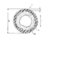
- FIG. 5 shows an example of the hollow porous membrane of the present invention in which a plurality of porous membrane layers are laminated on the outer peripheral surface of the support.
- symbol 10 shows a support body and the code
- the total film thickness t of the porous membrane layer and the inner and outer diameters of the hollow porous membrane will be described.
- the length indicated by the symbol D is the outer diameter D of the hollow porous membrane
- the length indicated by the symbol r is the inner diameter r of the hollow porous membrane.
- the inner diameter r is the length of a line obtained by connecting the convex and concave portions of the inner peripheral surface of the support 10 so as to be orthogonal to the axis (center line) of the hollow porous membrane.
- the length indicated by the symbol t is the total film thickness of the porous membrane layer.
- the total film thickness t is the length in the radial direction from the boundary between the layer 2 composed of the porous membrane layer and the uneven convex portion of the outer peripheral surface of the support 10 to the outermost surface of the hollow porous membrane.
- the total film thickness t of the porous membrane layer, the outer diameter D and the inner diameter r of the hollow porous membrane can be measured by the following method. First, several hollow porous membranes are bundled and the entire outside thereof is covered with polyurethane resin, and the hollow portion of each hollow porous membrane is filled with polyurethane resin and cured. Next, the cured bundle is sliced along the radial direction of the hollow porous membrane so that the length in the longitudinal direction is about 0.5 mm to obtain a flaky sample having a thickness of about 0.5 mm. Next, an optical image of the cross section of the sample is projected onto a screen at a magnification of, for example, 100 using a projector.
- the outer diameter D and inner diameter r of the hollow porous membrane and the total thickness t of the porous membrane layer are measured.
- the operation of cutting out and measuring the sample in this manner is repeated three times, and the average value of the three values is taken as the outer diameter D and inner diameter r of the hollow porous membrane and the total thickness t of the porous membrane layer.
- the water permeability of the hollow porous membrane is preferably 8 m 3 / m 2 / hr / MPa or more, and more preferably 10 m 3 / m 2 / hr / MPa or more. If the water permeability of the hollow porous membrane is 8 m 3 / m 2 / hr / MPa or more, even if the hollow porous membrane is worn and the membrane structure is plastically deformed, the water permeability performance is lowered. The membrane filtration operation is not affected.
- the hollow porous membrane of the present invention is prepared by preparing a film-forming stock solution for forming each porous membrane layer, and then coagulating each film-forming stock solution from each discharge port of the multi-tube spinning nozzle. It can manufacture by employ
- the film-forming stock solution is a liquid containing a resin and a solvent, which are materials for the porous membrane layer. That is, the raw film forming solution for the porous film layer formed using the thermoplastic resin (a) contains at least the thermoplastic resin (a) and the solvent.
- the solvent include N, N-dimethylformamide, N, N-dimethylacetamide, dimethyl sulfoxide, N-methyl-2-pyrrolidone and the like. From the point that the formed porous membrane layer has high water permeability, N, N N-dimethylacetamide or N-methyl-2-pyrrolidone is preferred.
- a hydrophilic polymer such as polyvinylpyrrolidone may be added to the film-forming stock solution for the purpose of adjusting the viscosity of the film-forming stock solution.
- the resin concentration in the membrane forming stock solution is preferably 5 to 30% by mass from the viewpoint that a suitable porous membrane structure can be formed and that the burst pressure of the hollow porous membrane can be easily controlled to 200 kPa or more. The mass% is more preferable.
- the coagulation liquid an aqueous solution containing the same solvent as the film forming stock solution is preferable.
- the solvent for forming the film is N, N-dimethylacetamide
- the concentration of the solvent is preferably 1 to 50% by mass in the coagulating liquid (100% by mass), and the temperature of the coagulating liquid is preferably 50 to 90 ° C.
- the concentration of the solvent is preferably 1 to 50% by mass in the coagulating liquid (100% by mass), and the temperature of the coagulating liquid is preferably 10 to 90 ° C.
- the hollow porous membrane has a braided string support formed by circularly knitting multifilaments and a plurality of porous membrane layers are laminated on the outer peripheral surface of the braided string support, It can manufacture by the method demonstrated to.
- a knitted string support in which multifilaments are circularly knitted into a cylindrical shape is manufactured.
- the braided string support can be manufactured by a manufacturing method having the following steps (a) and (b).
- Circular knitting is a method of knitting a cylindrical knitted fabric using a circular knitting machine.
- a knitted string obtained by circularly knitting multifilaments into a cylindrical shape is a spiral shape that curves the multifilaments.
- a continuous loop is formed, and these loops are related to each other in the front, rear, left, and right directions.
- a braided string support body can be manufactured, for example using the support body manufacturing apparatus shown in FIG.
- the support manufacturing apparatus 20 in FIG. 1 has a plurality of bobbins 22, a circular knitting machine 24 that circularly knits the multifilament 16 drawn from the bobbin 22, and a knitted string support 12 knitted by the circular knitting machine 24.
- a string supply device 26 that pulls with a tension of 10 mm, a mold 28 that heat-treats the braided string support 12, a take-up device 30 that takes up the heat-treated braided string support 12, and a bobbin using the braided string support 12 as the support 10.
- a winder 32 that winds the wire.
- the knitting speed varies slightly depending on the shape of the braided string support 12, but is substantially determined by the number of rotations of the cylinder.
- the number of rotations of the cylinder can be set to 1 to 4000 rpm, and 100 to 3000 rpm is preferable from the viewpoint of stable knitting.
- the knitted string support 12 knitted in this way has stretchability due to its structure. Therefore, in the next step (b), it is preferable that the knitted string support 12 is contracted by heat-treating the knitted string support 12 using the mold 28 to suppress stretchability (change in outer diameter). . Further, the braided string support 12 is not easily crushed by the heat treatment.
- the mold 28 includes a main body made of a metal block, a plate or the like in which through holes are formed at both ends in the longitudinal direction, and heating means. Examples of the heating means include a band heater and an aluminum cast heater.
- the treatment temperature in the mold 28 depends on the material of the multifilament 16, it is preferable to perform heat treatment at a temperature not lower than Tm (80 ° C.) and not higher than Tm when the melting point (or glass transition temperature) of the material is Tm.
- the treatment temperature is usually preferably 180 to 250 ° C, more preferably 190 to 230 ° C.
- the multifilament 16 may be fed from a plurality of bobbins 22 and combined. Multifilaments having a desired fineness and number of filaments can be supplied by combining the yarns. Further, even when the same type of multifilament 16 is used, the properties of the knitted string support 12 can be improved by combining the multifilaments 16 having different properties such as heat shrinkability or by combining different types of multifilaments 16. You may change it. In order to appropriately manage the tension, it is necessary to provide the tension adjusting device 23 for each multifilament when the multifilament 16 is combined.
- the string supply device 26 may not be installed. In this case, it is preferable to keep a constant tension by arranging a dancer roll or the like between the circular knitting machine 24 and the mold 28 by heat shrinkage of the knitted string support 12.
- a porous membrane layer is formed on the outer peripheral surface of the support manufactured as described above as follows.
- the thermoplastic resin (a) having a mass average molecular weight of 500,000 or more it can be produced, for example, by a method having the following steps (i) to (vii): .
- thermoplastic resin (a) whose mass mean molecular weight is 500,000 or more melt
- Vii A step of winding the hollow porous membrane.
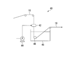
- FIG. 2 is a schematic configuration diagram showing an example of a hollow porous membrane manufacturing apparatus used in steps (i) to (ii).
- the hollow porous membrane manufacturing apparatus 40 includes a double tube spinning nozzle 42 for continuously applying a film forming raw solution to the support 10 continuously supplied from an unwinding device (not shown), and double tube spinning.
- a stock solution supply device 44 for supplying a film-forming stock solution to the nozzle 42, a coagulation bath 46 containing a coagulating liquid for coagulating the film-forming stock solution applied to the support 10, and a support 10 applied with the film-forming stock solution are coagulated.
- a guide roll 48 continuously introduced into the bathtub 46.
- a predetermined amount of the first film-forming stock solution is supplied from the stock solution supply device 44, and the first film-forming stock solution is applied to the outer peripheral surface of the support 10 to obtain a predetermined film thickness.
- the coating film is formed.
- the inner diameter of the pipe line of the double pipe spinning nozzle 42 is slightly larger than the outer diameter of the support body 10, and the inner peripheral surface of the pipe path of the double pipe spinning nozzle 42 and the support body 10 have a certain gap.
- the gap is determined by the thickness of the coating film, the viscosity of the stock solution, the running speed of the support 10 and the like.
- (V) Process For example, the hollow porous membrane is washed in hot water at 60 to 100 ° C. to remove the solvent, then washed with a chemical solution such as hypochlorous acid, and then washed in hot water at 60 to 100 ° C. Then remove the chemical.
- a chemical solution such as hypochlorous acid
- the hollow porous membrane is dried at 60 ° C. or higher and lower than 110 ° C. for 1 minute or longer and less than 24 hours, and then wound around a bobbin, a cassette or the like.
- the hollow porous membrane thus produced becomes a hollow porous membrane free from defects in the membrane caused by the single fiber end of the yarn splicing portion or the fiber breaking portion.
- the method of sequentially forming the first porous membrane layer and the second porous membrane layer using the double tube spinning nozzle 42 is exemplified, but the double tube spinning nozzle 42 is used.
- the double tube spinning nozzle 42 is used.
- two different types of film-forming stock solutions are discharged at the same time and guided to the coagulation bath so that the first porous film layer and the second porous film layer And may be formed simultaneously.
- the production method has been described by exemplifying a hollow porous membrane that includes the support 10 and has a porous membrane layer formed on the outer peripheral surface of the support 10.
- the hollow porous membrane of the present invention at least two of the porous membrane layers are formed using a thermoplastic resin having a mass average molecular weight of 500,000 or more, and burst when an internal pressure is applied.
- the pressure is 200 kPa or more and the virus removal performance when MS2 phage is used as a test bacterium is LRV4 or more, the support may not be provided.
- a pipe for passage of the support in the center is not an internal solidification but a support.
- the internal coagulation liquid is preferably an aqueous solution containing the same solvent as the film-forming stock solution.
- the hollow porous membrane having two porous membrane layers is exemplified and the manufacturing method thereof has been described.
- the hollow porous membrane having three or more porous membrane layers is described.
- a method of increasing the steps (iii) to (iv) according to the number of layers may be adopted.
- the so-called non-solvent induced phase separation method has been exemplified as the method for forming the porous membrane layer.
- a known thermally induced layer separation method may be employed.
- thermoplastic resin (a) having a mass average molecular weight of 500,000 or more, and the burst pressure when an internal pressure is applied.
- a hollow porous membrane having a pressure of 200 kPa or more has resistance to sticking to the membrane surface such as activated carbon and inorganic particles during air scrubbing treatment, and abrasion of the membrane surface by these particles, and thus high virus removal Performance can be maintained.
- a thin piece having a thickness of about 0.5 mm (corresponding to the length in the longitudinal direction of the hollow fiber membrane) was cut out using a razor blade.
- the sliced optical section of the sliced piece is projected onto a screen at a magnification of 100 times (objective lens) using a projector (Nikon Corporation, PROFILE PROJECTOR V-12).
- the outer diameter D of the hollow porous membrane, the total thickness t of the porous membrane layer, and the inner diameter r of the hollow porous membrane were read. This measurement was performed three times, and the average value of the measured values was defined as the outer diameter D of the hollow porous membrane, the total thickness t of the porous membrane layer, and the inner diameter r of the hollow porous membrane.
- the hollow porous membrane was cut into a length of 4 cm, and one end of the cut hollow porous membrane was sealed with a polyurethane resin.
- the sample was immersed in ethanol and the hollow porous membrane was evacuated for 5 minutes or more, and then the sample was immersed in pure water to replace the pores with pure water.
- a container containing pure water (25 ° C.) was prepared, the other end of the sample (that is, the open end not sealed with polyurethane resin) and the container were connected by a tube, and an air pressure of 100 kPa was applied in the container.
- pure water was allowed to flow out of the sample holes.
- the amount of pure water coming out of the hole was measured for 1 minute. This was measured three times to obtain an average value. This value was divided by the surface area of the sample, and the value converted to a pressure of 1 MPa was taken as the water permeation performance of the hollow porous membrane.
- the hollow porous membrane was cut into a length of 4 cm, and one end of the cut hollow porous membrane was sealed with a polyurethane resin.
- the sample is immersed in ethanol (25 ° C.), the other end of the sample is connected to the prepared container with a tube, and the internal pressure is gradually applied to the container with compressed air. Was measured. This measurement was performed three times, and the minimum value among the three measured pressure values was defined as the burst pressure of the hollow porous membrane.
- Samples ( ⁇ ) were prepared by bundling hollow porous membranes having a surface area of 280 cm 2 and sealing one end with a polyurethane resin.
- the sample ( ⁇ ) is immersed in a container containing pure water (25 ° C.), a tube is connected to the unsealed end of the sample ( ⁇ ), and an internal pressure is applied to the sample ( ⁇ ) with 100 kPa air through the tube. It was. At this time, generation of bubbles from the sample ( ⁇ ) was not observed. This confirmed that the sample ( ⁇ ) before the air scrubbing test had no defects.
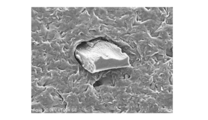
- a container having a capacity enough to contain the sample ( ⁇ ) is filled with pure water, and a wooden activated carbon (picahydroMP23 Pica USA, Inc) shown in FIG. 3 is added to the pure water to a concentration of 6000 ppm. Then, an activated carbon dispersion solution was prepared. After the sample ( ⁇ ) was immersed in ethanol and the hollow porous membrane was decompressed for 5 minutes or more, the sample ( ⁇ ) was immersed in pure water to replace the pores with pure water. Thereafter, the sample ( ⁇ ) was immersed in the activated carbon dispersion solution.
- Virus removal performance Escherichia coli phase MS2 (particle size: about 25 nm) was used as a test bacterium, grown in E. coli to the order of 10 6 pfu / ml, adjusted to pH 7 with 0.1 ml M phosphate buffer, and this was used as a test stock solution. And the virus removal performance of the hollow porous membrane was evaluated by the following nondestructive test. (1) Virus removal performance after air scrubbing test Both ends of the sample ( ⁇ ) used in the air scrubbing test were cut off, and the bundled hollow porous membrane was once separated. Thereafter, 15 of them were bundled again and bent into a U-shape. On the other hand, a cylindrical case with one end opened was prepared.
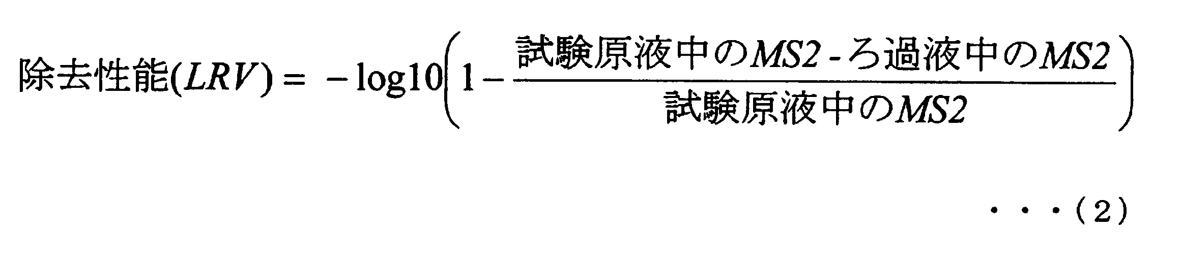
- the hollow porous membrane was fixed in the cylindrical case using polyurethane resin so that the opening of the both ends of the hollow porous membrane bent in the U shape was maintained. Then, 1000 ml of the phage solution is fed into the cylindrical case through a hole provided in the wall surface of the cylindrical case under a pressure of 20 kPa, and the phage solution is filtered into a hollow porous membrane by out-in. I let you. Then, the filtrate was taken out from the open end of the hollow porous membrane, and the final flow of 20 ml was sampled. MS2 of the test stock solution and the sampled filtrate was quantified, and the removal performance of MS2 phage after the air scrubbing test was calculated from the following formula (2).
- Virus removal performance before air scrubbing test The removal performance of MS2 phage before air scrubbing test was also calculated in the same manner as described above, except that a hollow porous membrane not subjected to air scrubbing test was used. .
- Example 1 In the following manner, two porous membrane layers made of polyvinylidene fluoride having a mass average molecular weight of 500,000 or more are formed on the outer peripheral surface of a knitted string support obtained by circularly knitting multifilaments in a cylindrical shape, and the burst pressure is reduced. A hollow porous membrane having a virus removal performance of LRV4 or higher when MS2 phage was used as a test bacterium at 200 kPa or higher was produced. In addition, as the knitted string support, a multi-filament made of polyester having a fineness of 167 dtex was circularly knitted using the support manufacturing apparatus of FIG.
- a hollow porous membrane was produced using the production apparatus shown in FIG.
- the knitted string support is passed through the center pipe line of the double tube spinning nozzle, the first film forming stock solution is fed from the outside, and the first film forming stock solution is applied to the outer peripheral surface of the knitted string support.
- the first porous membrane layer is solidified by being led to a first coagulation bath filled with an N-methyl-2-pyrrolidone aqueous solution (coagulation liquid) having a solvent concentration of 40% by mass and a temperature of 25 ° C. Formed.
- coagulation liquid N-methyl-2-pyrrolidone aqueous solution having a solvent concentration of 40% by mass and a temperature of 25 ° C. Formed.
- the second membrane-forming stock solution was applied onto the first porous membrane layer in the same manner as in the case of the first membrane-forming stock solution, and N-methyl having a solvent concentration of 30 mass% and a temperature of 61 ° C.
- a second porous film layer was formed by being guided to a second coagulation bath filled with a -2-pyrrolidone aqueous solution (coagulation liquid) and coagulating. After immersing this in a sodium hypochlorite solution at a normal temperature at a concentration of 13% by mass, staying in a steam atmosphere at 100 ° C. and then immersing it in warm water at 90 ° C. three times, The polyvinylpyrrolidone remaining in was washed and removed. After washing, moisture remaining in the membrane was evaporated in a drying oven heated to 105 ° C. and dried to obtain a hollow porous membrane.
- the obtained hollow porous membrane had an outer diameter of 1.56 mm, an inner diameter of 0.88 mm, a total thickness of the porous membrane layer made of polyvinylidene fluoride: 77 ⁇ m, a burst pressure: 343 kPa, pure
- the water permeability of water was 11.0 m 3 / m 2 / hr / MPa.
- the virus removal performance was 6.2 before the air scrubbing test and 5.4 after the test, and there was no significant decrease in the virus removal performance.
- Example 2 In the following manner, two porous membrane layers made of polyvinylidene fluoride having a mass average molecular weight of 500,000 or more are formed on the outer peripheral surface of a knitted string support obtained by circularly knitting multifilaments in a cylindrical shape, and the burst pressure is reduced. A hollow porous membrane having a virus removal performance of LRV4 or higher when MS2 phage was used as a test bacterium at 200 kPa or higher was produced.
- Second film-forming stock solution 15.2% by mass of polyvinylidene fluoride (mass average molecular weight: 1.1 ⁇ 10 6 ), 8.6% by mass of polyvinylpyrrolidone (mass average molecular weight: 4 ⁇ 10 4 ), and N-methyl- which is a solvent 76.2% by mass of 2-pyrrolidone was stirred and mixed at room temperature to obtain a second film-forming stock solution.
- the obtained hollow porous membrane has an outer diameter of 1.59 mm, an inner diameter of 0.91 mm, a total thickness of the porous membrane layer made of polyvinylidene fluoride: 86 ⁇ m, a burst pressure: 304 kPa, pure Water permeability of water: 13.5 m 3 / m 2 / hr / MPa.
- the virus removal performance was 6.8 before the air scrubbing test and 5.9 after the test, and there was no significant decrease in the virus removal performance.
- Example 3 In the following manner, two porous membrane layers made of polyvinylidene fluoride having a mass average molecular weight of 500,000 or more are formed on the outer peripheral surface of a knitted string support obtained by circularly knitting multifilaments in a cylindrical shape, and the burst pressure is 200 kPa.
- a hollow porous membrane having a virus removal performance of LRV4 or higher when MS2 phage was used as a test bacterium was produced.
- a hollow porous membrane was produced in the same manner as in Example 2 using the above-mentioned first membrane forming stock solution and second membrane forming stock solution.
- the obtained hollow porous membrane has an outer diameter of 1.60 mm, an inner diameter of 0.91 mm, a total thickness of a porous membrane layer made of polyvinylidene fluoride: 83 ⁇ m, a burst pressure: 230 kPa, pure Water permeability of water: 18.6 m 3 / m 2 / hr / MPa.
- the virus removal performance was 4.7 before the air scrubbing test and 4.2 after the test, and there was no significant decrease in the virus removal performance.
- a porous membrane layer made of polyvinylidene fluoride having a mass average molecular weight of 500,000 or more is formed on the outer peripheral surface of a braided string support formed by circularly knitting multifilaments in the following manner, and the burst pressure is 200 kPa.
- the above hollow porous membrane was manufactured.
- a hollow porous membrane was produced using the production apparatus shown in FIG.
- the knitted string support is passed through the center pipe line of the double tube spinning nozzle, the first film forming stock solution is fed from the outside, and the first film forming stock solution is applied to the outer peripheral surface of the knitted string support.
- the film was led to a first coagulation bath filled with an N-methyl-2-pyrrolidone aqueous solution (coagulation liquid) having a solvent concentration of 30% by mass and a temperature of 60 ° C., and coagulated to form a film.
- coagulation liquid N-methyl-2-pyrrolidone aqueous solution having a solvent concentration of 30% by mass and a temperature of 60 ° C.
- the obtained hollow porous membrane had an outer diameter of 1.50 mm, an inner diameter of 0.88 mm, and the total thickness (layer thickness) of the porous membrane layer made of polyvinylidene fluoride was 50 ⁇ m.
- the bursting pressure was 282 kPa, and the water permeability of pure water was 19.7 m 3 / m 2 / hr / MPa.
- the virus removal performance was 2.3 after the air scrubbing test and was greatly reduced from 4.8 before the test.
- Second film-forming stock solution 15.0% by mass of polyvinylidene fluoride (mass average molecular weight: 6.8 ⁇ 10 5 ), 17.7% by mass of polyvinylpyrrolidone (mass average molecular weight: 4.0 ⁇ 10 4 ), and N— which is a solvent 67.3 mass% of methyl-2-pyrrolidone was stirred and mixed at room temperature to obtain a second film-forming stock solution.
- a hollow porous membrane was produced in the same manner as in Example 1 using the above-mentioned first membrane forming stock solution and second membrane forming stock solution. However, an N-methyl-2-pyrrolidone aqueous solution (coagulation liquid) having a solvent concentration of 30% by mass and a temperature of 55 ° C. is used for the first coagulation bath, and a concentration of 30% by mass is used for the second coagulation tank. An N-methyl-2-pyrrolidone aqueous solution (coagulation solution) having a temperature of 59 ° C. was used.
- the obtained hollow porous membrane had an outer diameter of 1.66 mm, an inner diameter of 0.91 mm, a total thickness of the porous membrane layer made of polyvinylidene fluoride: 93 ⁇ m, a burst pressure of 159 kPa, pure Water permeability of water: 7.1 m 3 / m 2 / hr / MPa.
- the virus removal performance (LRV) was 2.0 before the air scrubbing test. Further, defect points were generated in the air scrubbing test.
- the hollow porous membrane having a bursting pressure of less than 200 kPa even if it has two layers made of the thermoplastic resin (a) Can be manufactured.
- a defect point is likely to occur due to the burst pressure being less than 200 kPa, so that a defect point is generated in the air scrubbing test.
- a porous membrane layer made of polyvinylidene fluoride was formed one by one to produce a hollow porous membrane having a burst pressure of 200 kPa or more.
- a hollow porous membrane was produced using the production apparatus shown in FIG. However, a triple pipe spinning nozzle was used instead of the double pipe spinning nozzle 42.
- the knitted string support is passed through the central pipe line of the triple tube spinning nozzle, and the first film forming solution and the second film forming solution are simultaneously fed from the outside to the outer peripheral surface of the knitted string support.
- the solution was filled with an aqueous N, N-dimethylacetamide solution (coagulating solution) having a solvent concentration of 20% by mass and a temperature of 64 ° C.
- the first coagulation bath was led and solidified to form a film.
- the obtained hollow porous membrane has an outer diameter of 1.62 mm, an inner diameter of 0.88 mm, a total thickness of the porous membrane layer made of polyvinylidene fluoride: 98 ⁇ m, a burst pressure: 242 kPa, pure
- the water permeability of water was 19.8 m 3 / m 2 / hr / MPa.
- the virus removal performance (LRV) was 6.4 before the air scrubbing test. Further, defect points were generated in the air scrubbing test.
- the mass average molecular weight of the two kinds of mixtures was calculated as 4.3 ⁇ 10 5 from the formula (1).
- Polyvinylidene fluoride weight average molecular weight: 5.5 ⁇ 10 5) and 12.0 wt% of polyvinylidene fluoride (weight average molecular weight: 2.5 ⁇ 10 5) and 8.0 wt% of polyvinylpyrrolidone (weight 10.0% by mass of average molecular weight: 1.3 ⁇ 10 6 ) and 70.0% by mass of N, N-dimethylacetamide as a solvent are stirred and mixed at room temperature to obtain a second film-forming stock solution. It was.
- a hollow porous membrane was produced in the same manner as in Example 1 using the above-mentioned first membrane forming stock solution and second membrane forming stock solution. However, an N, N-dimethylacetamide aqueous solution (coagulating liquid) having a solvent concentration of 5 mass% and a temperature of 80 ° C. was used for the first coagulating bath.
- the obtained hollow porous membrane had an outer diameter of 2.72 mm, an inner diameter of 1.20 mm, a total thickness of the porous membrane layer made of polyvinylidene fluoride: 433 ⁇ m, a burst pressure: 208 kPa, pure Water permeability of water: 84.7 m 3 / m 2 / hr / MPa.
- the virus removal performance (LRV) was 0.04 before the air scrubbing test, and the virus removal performance was not sufficient.
- the hollow porous membrane of each example having two porous membrane layers made of polyvinylidene fluoride having a mass average molecular weight of 500,000 or more and having a burst pressure of 200 kPa or more was subjected to an air scrubbing test in the presence of activated carbon. Even if it did, it had no defects and was resistant to abrasion of the membrane surface by activated carbon, and therefore maintained high virus removal performance.
- the hollow porous membrane of the comparative example was activated by the activated carbon scrubbing test, and the membrane surface was worn out even if no defect point or defect point occurred. The removal performance decreased.
- the hollow porous membrane of the present invention has resistance to the surface of the membrane such as activated carbon and inorganic particles during air scrubbing and the like, and wear resistance of the membrane surface due to these particles. High virus removal performance can be maintained. Therefore, according to the hollow porous membrane of the present invention, it is possible to provide safe treated water with a low risk of remaining viruses, and it is suitably used for water treatment by precision filtration such as sewage treatment and water purification, ultrafiltration, and the like. . In addition, since it is also resistant to abrasion due to contact with inorganic substances, it is also suitable for use in combination with activated carbon.
Landscapes
- Chemical & Material Sciences (AREA)
- Chemical Kinetics & Catalysis (AREA)
- Engineering & Computer Science (AREA)
- Materials Engineering (AREA)
- Health & Medical Sciences (AREA)
- Medicinal Chemistry (AREA)
- Polymers & Plastics (AREA)
- Organic Chemistry (AREA)
- Separation Using Semi-Permeable Membranes (AREA)
- Manufacture Of Porous Articles, And Recovery And Treatment Of Waste Products (AREA)
Description
本願は、2012年06月01日に、日本に出願された特願2012-125875号に基づき優先権を主張し、その内容をここに援用する。
中空状多孔質膜としては、種々の構成のものが検討されている。例えば、糸を円筒状に丸編みした編紐支持体を中空状多孔質膜用支持体(以下、単に支持体という場合がある。)として用い、その外周面に多孔質膜層を設けた中空状多孔質膜がある。該中空状多孔質膜は、例えば次のように製造される。まず、支持体を2重管紡糸ノズルに連続的に通す際に、2重管紡糸ノズルから製膜原液を吐出し、支持体の外周面に製膜原液を塗布する。その後、製膜原液が塗布された支持体を凝固浴槽に通し、凝固浴槽内の凝固液で製膜原液を凝固させる。これにより、中空状多孔質膜が得られる。
また、各種水処理において中空状多孔質膜が活性炭と併用された場合や、処理原水中に砂などの無機粒子が含まれる場合には、エアスクラビング処理時などに膜表面と活性炭や無機粒子とが接触し、膜表面が磨耗したり、膜表面に活性炭や無機粒子が突き刺さって膜に欠陥点が生じたりし、膜の濾過性能が低下することがある。よって、中空状多孔質膜には、このような突き刺さりや磨耗に対する耐性を備え、そのために、活性炭との併用時や、処理原水中に無機粒子が含まれる場合であっても、ウイルスの除去性能を維持できることが求められる。ウイルスの除去機構としては、一般に、ウイルスより小さい孔径でろ過を行うシービング(篩い分け)濾過、ウイルスを細孔内で捕捉する、いわゆるデプス濾過等がある。
また、特許文献2には、質量平均分子量40万以上の熱可塑性樹脂からなる外層と、質量平均分子量40万未満の熱可塑性樹脂からなる軟らかい内層とを有する中空状多孔質膜が開示されている。特許文献2には、この中空状多孔質膜は、内層が軟らかいために、膜同士が接触した際の外表面における押し圧が分散・低下され、擦過を低減させることができると記載されている。
また、特許文献3には、膜表面と膜内部とに緻密層を有する中空状多孔質膜が開示されている。特許文献3には、この中空状多孔質膜は、膜表面の緻密層に傷が発生して、除去対象物質の阻止率が低下したとしても、膜内部の緻密層が除去対象物質を阻止するため、極めて高い安全性を維持できると記載されている。
また、特許文献2に開示された膜は、磨耗に対する耐性はたとえ備えていたとしても、突き刺さりに対する耐性は充分とは言えない。
また、特許文献3の実施例1および2に記載された膜は、元々の平均孔径が80nmと大きいうえ、落砂試験によって平均孔径が80nmから100nmへと変化しており、粒径が数十~50nmの小さなウイルスの除去性能を維持できるものではない。
本発明の中空状多孔質膜は、以下の態様を有する。
[1]複数の多孔質膜層を有する中空状多孔質膜であって、多孔質膜層のうちの少なくとも2層が、質量平均分子量が50万以上の熱可塑性樹脂(a)を用いて形成され、前記中空状多孔質膜は、内圧をかけた際の破裂圧が200kPa以上であり、かつ、MS2ファージを供試菌として用いた場合のウイルス除去性能がLRV4以上である中空状多孔質膜。
[2]前記熱可塑性樹脂(a)がポリフッ化ビニリデンである、[1]に記載の中空状多孔質膜。
[3]マルチフィラメントからなる筒状の支持体を備え、前記複数の多孔質膜層は前記支持体の外周面に積層されている、[1]または[2]のいずれかに記載の中空状多孔質膜。
[4]前記マルチフィラメントからなる筒状の支持体が、円筒状に丸編みした編紐支持体である[3]に記載の中空状多孔質膜。
[5]前記マルチフィラメントがポリエステルである[3]または[4]のいずれかに記載の中空状多孔質膜。
[6]前記マルチフィラメントの繊度が50~1000dtexである[3]~[5]のいずれかに記載の中空状多孔質膜。
[7]前記熱可塑性樹脂(a)を用いて形成される層のうちの少なくとも一層は、分子量の異なる複数種の熱可塑性樹脂の混合物を用いて形成された[1]~[6]のいずれかに記載の中空状多孔質膜。
[8]前記熱可塑性樹脂(a)を用いて形成される層のうち、最も外側の層に使用される熱可塑性樹脂(a)の質量平均分子量が、それ以外の各層に使用される熱可塑性樹脂(a)の質量平均分子量よりも大きい[1]~[7]のいずれかに記載の中空状多孔質膜。
[9]前記支持体が、熱処理された支持体である[3]~[6]のいずれかに記載の中空状多孔質膜。
[10]外径が1.0~5.0mmである[1]~[9]のいずれかに記載の中空状多孔質膜。
[11]前記複数種の熱可塑性樹脂は、いずれも質量平均分子量が40万以上である[7]に記載の中空状多孔質膜。
[12]熱可塑性樹脂(a)を用いて形成される層のうち、最も外側の層に使用される熱可塑性樹脂(a)の質量平均分子量が60万以上である[1]~[11]のいずれかに記載の中空状多孔質膜。
[13]前記複数の多孔質膜層の総膜厚が50μm以上200μm以下である[1]~[12]のいずれかに記載の中空状多孔質膜。
[14]透水性能が8m3/m2/hr/MPa以上である[1]~[13]のいずれかに記載の中空状多孔質膜。
[15]内径が0.6mm以上である[1]~[14]のいずれかに記載の中空状多孔質膜。
[16]全ての多孔質膜層が、質量平均分子量が50万以上の熱可塑性樹脂(a)から形成されている[1]~[15]のいずれかに記載の中空状多孔質膜。
<中空状多孔質膜>
本発明の中空状多孔質膜は、複数の多孔質膜層を有する中空状多孔質膜であって、多孔質膜層のうちの少なくとも2層が、質量平均分子量が50万以上の熱可塑性樹脂(a)を用いて形成されている。また、本発明の中空状多孔質膜は、内圧をかけた際の破裂圧が200kPa以上、かつ、MS2ファージを供試菌として用いた場合のウイルス除去性能がLRV4以上とされている。
まず、サンプルをエタノール(25℃)中に浸漬する。一方、容器を用意する。ついで、サンプルの他端(すなわち、ポリウレタン樹脂で封じていない方の開放端部)と容器とをチューブで繋ぎ、容器内に圧縮空気により徐々に内圧をかけていき、サンプルの中空部に圧力がかかるようにする。そして、サンプルの膜が破裂した時の圧力値を測定する。この測定を3回実施し、測定された3回の圧力値のうちの最小値を中空状多孔質膜の破裂圧とする。
また、MS2ファージを供試菌として用いた場合のウイルス除去性能を測定する方法は、詳しくは後述するが、以下のとおりである。供試菌としてEscherichia coli phage MS2(粒径約25nm)を用い、大腸菌中で106pfu/mlオーダーに増殖させ、0.1mlMリン酸バッファーにてpH7に調製し、これを試験原液とする。そして、後述の非破壊性の除去性能試験を行う。この結果より、除去性能の指標であるLRVを算出する。
LRV4以上とは、すなわち、流した供試菌の99.99%以上を阻止することを表している。米国環境保護庁(USEPA)の「National primary drinking water standards」において、表層水を飲料水に適用させるには、ウイルスを99.99%以上除去する必要があることが明記されていることからも、ウイルスの除去性能はLRV4以上であることが望ましく、LRV4.5以上であるとより好ましい。
そして、このような多孔質膜層を2層以上形成することによって、これらの層のうち外側の層が仮に磨耗して孔径が増大するなどし、ウイルス除去性能が低下した場合であっても、内側の層により、ウイルス除去性能を維持することができる。
また、中空状多孔質膜の破裂圧が200kPa以上であると、中空状多孔質膜の膜表面に活性炭や無機粒子が突き刺さりにくく、欠陥点が生じにくい。
その結果、これらの場合、MS2ファージを供試菌として用いた場合のウイルス除去性能がLRV4以上との要件を満たさなくなる。
中空状多孔質膜の破裂圧は、好ましくは220kPa以上である。破裂圧の上限値は特に制限されないが、製造面から、現実的には1000kPaである。
熱可塑性樹脂(a)としては、異なる種類、異なる分子量の樹脂を複数種混合して使用してもよく、その場合には、混合物としての質量平均分子量が50万以上であればよい。ただし、混合物の分子量分布が低分子量側に広くなると、該混合物から形成された多孔質膜層において、局所的に欠陥点が生じやすくなるため、混合前の複数種の熱可塑性樹脂は、いずれも質量平均分子量が40万以上であることが好ましい。
質量平均分子量が(Mw)1である熱可塑性樹脂(1)と、質量平均分子量が(Mw)2である熱可塑性樹脂(2)とをw1:w2の質量比率(ただし、w1+w2=1。)で混合して、これを熱可塑性樹脂(a)として使用する場合には、混合物としての質量平均分子量Mwは、「日本レオロジー学会誌,Vol.28(2000),No.3 p99-103」に記載の下記式(1)により求められる。

また、質量平均分子量50万以上の熱可塑性樹脂(a)を用いて形成される多孔質膜層の層数が2層以上であれば、中空状多孔質膜の破裂圧を200kPa以上に制御しやすいが、熱可塑性樹脂(a)を用いて形成される層のうち、最も外側の層に使用される熱可塑性樹脂(a)の質量平均分子量が、それ以外の各層に使用される熱可塑性樹脂(a)の質量平均分子量よりも大きいと、中空状多孔質膜の破裂圧を200kPa以上により制御しやすい。また、その場合、最も外側の層に使用される熱可塑性樹脂(a)の質量平均分子量をより好ましくは60万以上とし、さらに好ましくは70万以上とすると、中空状多孔質膜の破裂圧を200kPa以上により一層制御しやすい。
また、中空状多孔質膜は、マルチフィラメントを円筒状などの筒状に丸編みした編紐支持体などの支持体(中空状多孔質膜用支持体)を具備するものでもよく、このような支持体を具備することにより、破裂圧を200kPa以上にしやすくなる傾向にある。
本発明の好ましい形態としては、支持体を備え、該支持体の外周面に積層された全ての多孔質膜層が、質量平均分子量が50万以上の熱可塑性樹脂(a)から形成されている中空状多孔質膜が挙げられる。
合成繊維としては、ナイロン6、ナイロン66、芳香族ポリアミド等のポリアミド系繊維;ポリエチレンテレフタレート、ポリブチレンテレフタレート、ポリ乳酸、ポリグリコール酸等のポリエステル系繊維;ポリアクリロニトリル等のアクリル系繊維;ポリエチレン、ポリプロピレン等のポリオレフィン系繊維;ポリビニルアルコール系繊維;ポリ塩化ビニリデン系繊維;ポリ塩化ビニル系繊維;ポリウレタン系繊維;フェノール樹脂系繊維;ポリフッ化ビニリデン、ポリテトラフルオロエチレン等のフッ素系繊維;ポリアルキレンパラオキシベンゾエート系繊維等が挙げられる。
半合成繊維としては、セルロースジアセテート、セルローストリアセテート、キチン、キトサン等を原料としたセルロース誘導体系繊維:プロミックスと呼称される蛋白質系繊維等が挙げられる。再生繊維としては、ビスコース法、銅-アンモニア法、有機溶剤法等により得られるセルロース系再生繊維(レーヨン、キュプラ、ポリノジック等。)が挙げられる。天然繊維としては、亜麻、黄麻等が挙げられる。
マルチフィラメントの繊度は、中空状多孔質膜の破断強度や、外径制御のしやすさから、50~1000dtexが好ましく、100~400dtexがより好ましい。
また、中空状多孔質膜の外径は、潰れに対する中空形状維持の観点から1.0~5.0mm程度が好ましく、より好ましくは1.2mm~3.0mm程度である。また、中空状多孔質膜の内径は、管内抵抗による透水性能を抑制する観点から0.6mm以上が好ましく、0.7mm以上がより好ましい。
図5において、符号Dで示す長さが、中空状多孔質膜の外径Dで、符号rで示す長さが、中空状多孔質膜の内径rである。内径rは、支持体10の内周面の凹凸の凸部分どうしを、中空状多孔質膜の軸線(中心線)と直交するように結んだ線の長さをいう。
図5において、符号tで示す長さが、多孔質膜層の総膜厚である。総膜厚tは、多孔質膜層からなる層2と支持体10の外周面の凹凸の凸部分との境界から、中空状多孔質膜の最外表面までの径方向の長さである。
まず、中空状多孔質膜を数本束ねて、その外側全体をポリウレタン樹脂で覆うとともに、各中空状多孔質膜の中空部にもポリウレタン樹脂を充填し、硬化させる。ついで、硬化した束を中空状多孔質膜の径方向に沿って、その長手方向の長さが約0.5mmとなるようにスライスし、厚み約0.5mmの薄片状のサンプルを得る。ついで、このサンプルの断面の光学像を投影機を用いて例えば100倍の倍率でスクリーンに投影する。投影された像において、中空状多孔質膜の外径Dおよび内径r、多孔質膜層の総膜厚tを測定する。
このようにサンプルを切り出して測定する操作を3回繰り返し、3回の数値の平均値をもって、中空状多孔質膜の外径Dおよび内径r、多孔質膜層の総膜厚tとする。
本発明の中空状多孔質膜は、各多孔質膜層を形成するための製膜原液をそれぞれ調製し、ついで、各製膜原液を多重管紡糸ノズルの各吐出口から凝固液が入った凝固浴槽中に吐出し、凝固させる方法など、公知の方法を採用して製造できる。
溶剤としては、N,N-ジメチルホルムアミド、N,N-ジメチルアセトアミド、ジメチルスルホキシド、N-メチル-2-ピロリドン等が挙げられ、形成される多孔質膜層の透水性が高い点から、N,N-ジメチルアセトアミドもしくはN-メチル-2-ピロリドンが好ましい。製膜原液には、製膜原液の粘度を調整する目的などで、ポリビニルピロリドンなどの親水性ポリマーを添加してもよい。
製膜原液中の樹脂濃度は、好適な多孔質膜構造を形成でき、また、中空状多孔質膜の破裂圧を200kPa以上に制御しやすい観点から、5~30質量%が好ましく、10~20質量%がより好ましい。
(a)マルチフィラメントを筒状に丸編みする工程。
(b)丸編みした筒状のマルチフィラメントを熱処理し、収縮させる工程。
図1の支持体製造装置20は、複数のボビン22と、ボビン22から引き出されたマルチフィラメント16を丸編する丸編機24と、丸編機24によって編成された編紐支持体12を一定の張力で引っ張る紐供給装置26と、編紐支持体12を熱処理する金型28と、熱処理された編紐支持体12を引き取る引取り装置30と、編紐支持体12を支持体10としてボビンに巻き取る巻取り機32とを具備している。
工程(a)では、マルチフィラメント16を丸編して編紐支持体12を編成する。製編速度は、編紐支持体12の形状により若干変わるが、シリンダの回転数によってほぼ決まる。シリンダ回転数は、1~4000rpmに設定可能であり、安定して編成できる点から、100~3000rpmが好ましい。
こうして編成された編紐支持体12は、その構造上、伸縮性を有している。よって、次の工程(b)では、編紐支持体12に金型28を用いて熱処理を施すことによって、編紐支持体12を収縮させ、伸縮性(外径変化)を抑制することが好ましい。また、熱処理によって、編紐支持体12は潰れにくくなる。
工程(b)では、丸編機24によって丸編された編紐支持体12を金型28によって熱処理する。金型28は、長手方向両端に貫通孔が形成された金属製のブロック、プレート等からなる本体と、加熱手段とを有して構成される。加熱手段としては、バンドヒーター、アルミ鋳込みヒーター等が挙げられる。
また、マルチフィラメント16の熱収縮率が小さい場合、紐供給装置26を設置しなくてもよい。この場合、編紐支持体12の熱収縮により丸編機24と金型28との間にダンサーロール等を配置して張力を一定に保つとよい。
(i)支持体の外周面に、質量平均分子量が50万以上の熱可塑性樹脂(a)が溶解した第1の製膜原液を塗布する工程。
(ii)支持体に塗布された第1の製膜原液を凝固させて、第1の多孔質膜層を形成し、中空状多孔質膜前駆体を得る工程。
(iii)中空状多孔質膜前駆体の外周面に、質量平均分子量が50万以上の熱可塑性樹脂(a)が溶解した第2の製膜原液を塗布する工程。
(iv)中空状多孔質膜前駆体に塗布された第2の製膜原液を凝固させて、第2の多孔質膜層を形成し、中空状多孔質膜を得る工程。
(v)中空状多孔質膜を洗浄する工程。
(vi)中空状多孔質膜を乾燥する工程。
(vii)中空状多孔質膜を巻き取る工程。
2重管紡糸ノズル42の中央には、支持体10が通過する管路が形成されている。管路の途中には、管路の円周方向にスリット状の製膜原液吐出口が形成され、製膜原液を吐出する構造となっている。支持体10が管路を通過する際、原液供給装置44から第1の製膜原液が一定量で供給され、支持体10の外周面に第1の製膜原液が塗布されて所定の膜厚の塗膜が形成される。
凝固浴槽46内の凝固液と第1の製膜原液の塗膜とを接触させ、第1の製膜原液を凝固させて、第1の多孔質膜層を形成し、中空状多孔質膜前駆体18を得る。
なお、(ii)工程と(iii)工程との間でも、後述の(v)~(vii)工程を行ってもよい。
(i)~(ii)工程で用いた装置と同様の装置を用い、(i)~(ii)工程と同様な条件にて、中空状多孔質膜前駆体18の外周面に第2の製膜原液を塗布し、第2の多孔質膜層を形成し、中空状多孔質膜を得る。
例えば、中空状多孔質膜を60~100℃の熱水中で洗浄して溶剤を除去し、ついで、次亜塩素酸等の薬液で洗浄し、ついで、60~100℃の熱水中で洗浄して薬液を除去する。
中空状多孔質膜を、60℃以上110℃未満で、1分以上24時間未満乾燥した後、ボビン、カセ等に巻き取る。
このようにして製造された中空状多孔質膜は、糸継ぎ部または繊維破断部の単繊維端に起因する膜の欠陥点のない中空状多孔質膜となる。
また、上述の説明においては、多孔質膜層の形成方法として、いわゆる非溶媒誘起相分離法を例示して説明したが、例えば、公知の熱誘起層分離法を採用してもよい。
(中空状多孔質膜の外径、内径および多孔質膜層の膜厚)
支持体を有する中空状多孔質膜について、中空状多孔質膜の外径D、多孔質膜層の総膜厚tおよび中空状多孔質膜の内径rを、以下の方法で測定した。
支持体を有する中空状多孔質膜のサンプルを約10cmに切断した。切断後のサンプルを数本束ねた後、サンプル全体をポリウレタン樹脂で被覆した。ポリウレタン樹脂は支持体の中空部にも入るようにした。ポリウレタン樹脂が硬化した後、カミソリ刃を用いて厚さ(中空糸膜の長手方向の長さに相当)約0.5mmの薄片を切り出した。次に、切り出した薄片断面の光学象を、投影機(ニコン社製、PROFILE PROJECTOR V-12)を用いて、倍率100倍(対物レンズ)にてスクリーンに投影し、投影された像からサンプルの中空状多孔質膜の外径D、多孔質膜層の総膜厚tおよび中空状多孔質膜の内径rを読み取った。この測定を3回行い、測定された数値の平均値を中空状多孔質膜の外径D、多孔質膜層の総膜厚tおよび中空状多孔質膜の内径rとした。
中空状多孔質膜を長さ4cmに切断し、切断された中空状多孔質膜の一端をポリウレタン樹脂で封じたものをサンプルとした。該サンプルをエタノールに浸漬し、中空状多孔質膜内を5分間以上減圧する操作を行った後、該サンプルを純水に浸して、細孔部内を純水で置換した。
ついで、純水(25℃)を入れた容器を準備し、サンプルの他端(すなわち、ポリウレタン樹脂で封じていない方の開放端部)と容器とをチューブで繋ぎ、容器内に100kPaの空気圧をかけることにより、サンプルの孔から純水を流出させた。このようにして孔から出た純水の量を1分間測定した。これを3回測定して平均値を求めた。この数値をサンプルの表面積で割り、1MPaの圧力に換算した値を中空状多孔質膜の透水性能とした。
中空状多孔質膜を長さ4cmに切断し、切断された中空状多孔質膜の一端をポリウレタン樹脂で封じたものをサンプルとした。該サンプルをエタノール(25℃)に浸漬し、サンプルの他端と、用意された容器とをチューブで繋ぎ、容器内に圧縮空気により徐々に内圧をかけていき、サンプルが破裂した時の圧力値を測定した。この測定を3回実施し、測定された3回の圧力値のうちの最小値を中空状多孔質膜の破裂圧とした。
長さ35cmに切断された中空状多孔質膜を表面積が280cm2となる本数だけ束ね、ポリウレタン樹脂で一端を封止したものをサンプル(α)とした。
純水(25℃)を入れた容器にサンプル(α)を浸漬し、サンプル(α)の封止していない端部にチューブを繋ぎ、チューブを通じてサンプル(α)に100kPaの空気により内圧をかけた。このとき、サンプル(α)からの気泡の発生は認められなかった。これにより、エアスクラビング試験前のサンプル(α)には欠陥点がないことを確認した。
一方、このサンプル(α)が充分に入る容量の容器に純水を満たし、該純水中に図3に示す木質系の活性炭(picahydroMP23 Pica USA,Inc)を濃度6000ppmとなるように添加して、活性炭分散溶液を調製した。サンプル(α)をエタノールに浸漬し、中空状多孔質膜内を5分間以上減圧する操作を行った後、該サンプル(α)を純水に浸して、細孔部内を純水で置換した。その後、サンプル(α)を活性炭分散溶液中に浸漬させた。活性炭分散溶液が入った容器の下部より、35Nm3/m2/hrの空気を連続的に35日間供給し、エアスクラビング試験を行った。
なお、上述の木質系の活性炭は、鋭利な形状を有し、膜に突き刺さりやすい。よって、この木質系の活性炭を用いたエアスクラビング試験により、活性炭の突き刺さりが生じない膜は、他の種類の活性炭や、砂、カオリンなどの無機粒子の突き刺さりも起こらないものと考えることができる。
エアスクラビング試験前の確認と同様に、純水(25℃)を入れた容器を用意した。該容器に、上記のエアスクラビング試験を行った後のサンプル(α)を浸漬し、サンプル(α)の封止していない端部にチューブを繋ぎ、チューブを通じてサンプル(α)に100kPaの空気により内圧をかけた。このとき、サンプル(α)から発生する気泡の有無を目視で確認し、それによりエアスクラビング試験後のサンプル(α)の欠陥点の有無を調べた。
供試菌としてEscherichia coli phage MS2(粒径約25nm)を用い、大腸菌中で106pfu/mlオーダーに増殖させ、0.1mlMリン酸バッファーにてpH7に調製し、これを試験原液とした。そして、次の非破壊性試験により、中空状多孔質膜のウイルス除去性能を評価した。
(1)エアスクラビング試験後のウイルス除去性能
エアスクラビング試験に用いた上述のサンプル(α)の両端部を切り落とし、束ねられていた中空状多孔質膜を一旦ばらばらにした。その後、それらのうちの15本を再度束ねてU字に曲げた。一方、一端が開口した筒状ケースを用意した。そして、U字状に曲げられた中空状多孔質膜の両端の開口が維持されるように、ポリウレタン樹脂を用いて、中空状多孔質膜を筒状ケース内に固定した。そして、筒状ケースの壁面に設けられた穴から、筒状ケース内に、1000mlのファージ溶液を20kPaの圧力をかけて送液し、out-inにより、ファージ溶液を中空状多孔質膜に濾過させた。そして、中空状多孔質膜の開口した端部から濾過液を取り出し、その終流20mlをサンプリングした。試験原液、サンプリングされた濾過液のMS2をそれぞれ定量し、以下の式(2)より、エアスクラビング試験後のMS2ファージの除去性能を算出した。
なお、欠陥点が生じた場合、ウイルス除去性能は顕著に低下することがわかっているため、エアスクラビング試験後のウイルス除去性能評価は、エアスクラビング試験後に欠陥点が認められなかったサンプルに対してのみ実施した。
(2)エアスクラビング試験前のウイルス除去性能
エアスクラビング試験を行っていない中空状多孔質膜を用いた以外は、上述の方法と同様にして、エアスクラビング試験前のMS2ファージの除去性能も算出した。
次のようにして、マルチフィラメントを円筒状に丸編みした編紐支持体の外周面に、質量平均分子量が50万以上のポリフッ化ビニリデンからなる多孔質膜層が2層形成され、破裂圧が200kPa以上で、MS2ファージを供試菌として用いた場合のウイルス除去性能がLRV4以上である中空状多孔質膜を製造した。
なお、編紐支持体としては、図1の支持体製造装置を用いて、繊度167dtexのポリエステル製のマルチフィラメントを円筒状に丸編みしたものを使用した。
ポリフッ化ビニリデン(質量平均分子量:6.8×10⁵)の12.9質量%と、ポリビニルピロリドン(質量平均分子量:4.0×10⁴)の11.9質量%と、溶媒であるN-メチル-2-ピロリドンの75.2質量%を常温にて撹拌混合して、第1の製膜原液を得た。
(第2の製膜原液の調製)
ポリフッ化ビニリデン(質量平均分子量:1.1×10⁶)の18.3質量%と、ポリビニルピロリドン(質量平均分子量:4.0×10⁴)の8.3質量%と、溶媒であるN-メチルピロリドンの73.4質量%を常温にて撹拌混合して、第2の製膜原液を得た。
(中空状多孔質膜の製造)
2重管紡糸ノズルの中央の管路に編紐支持体を通過させるとともに、その外側から第1の製膜原液を送液し、編紐支持体の外周面に第1の製膜原液を塗布した後、溶剤濃度が40質量%で温度が25℃のN-メチル-2-ピロリドン水溶液(凝固液)で満たされている第1の凝固浴槽へ導き、凝固させて第1の多孔質膜層を形成した。
次いで、第2の製膜原液を、第1の製膜原液の場合と同様にして、第1の多孔質膜層上に塗布し、溶剤濃度が30質量%で温度が61℃のN-メチル-2-ピロリドン水溶液(凝固液)で満たされている第2の凝固浴槽へ導き、凝固することで第2の多孔質膜層を形成した。
これを濃度13質量%で常温の次亜塩素酸ナトリウム溶液に浸漬した後、100℃の水蒸気雰囲気中に滞在させ、さらに90℃の温水中に浸漬するという一連の工程を3回繰り返し、膜中に残存するポリビニルピロリドンを洗浄、除去した。
洗浄の後に、105℃に熱した乾燥炉にて膜中に残存する水分を蒸発させて乾燥し、中空状多孔質膜を得た。
次のようにして、マルチフィラメントを円筒状に丸編みした編紐支持体の外周面に、質量平均分子量が50万以上のポリフッ化ビニリデンからなる多孔質膜層が2層形成され、破裂圧が200kPa以上で、MS2ファージを供試菌として用いた場合のウイルス除去性能がLRV4以上である中空状多孔質膜を製造した。
(第1の製膜原液の調製)
ポリフッ化ビニリデン(質量平均分子量:6.8×10⁵)の12.9質量%と、ポリビニルピロリドン(質量平均分子量:4×10⁴)の11.9質量%と、溶媒であるN-メチル-2-ピロリドンの75.2質量%を常温にて撹拌混合して、第1の製膜原液を得た。
(第2の製膜原液の調製)
ポリフッ化ビニリデン(質量平均分子量:1.1×10⁶)の15.2質量%と、ポリビニルピロリドン(質量平均分子量:4×10⁴)の8.6質量%と、溶媒であるN-メチル-2-ピロリドンの76.2質量%を常温にて撹拌混合して、第2の製膜原液を得た。
上述の第1の製膜原液、第2の製膜原液を用い、第1の凝固浴槽のN-メチル-2-ピロリドン水溶液(凝固液)の濃度を30質量%とし、温度を25℃とした以外は、実施例1と同様にして、中空状多孔質膜を製造した。
次のようにして、マルチフィラメントを円筒状に丸編みした編紐支持体の外周面に、質量平均分子量が50万以上のポリフッ化ビニリデンからなる多孔質膜層が2層形成され、破裂圧200kPa以上で、MS2ファージを供試菌として用いた場合のウイルス除去性能がLRV4以上である中空状多孔質膜を製造した。
(第1の製膜原液の調製)
ポリフッ化ビニリデン(質量平均分子量:6.8×10⁵)の11.1質量%と、ポリビニルピロリドン(質量平均分子量:4×10⁴)の12.1質量%と、溶媒であるN-メチル-2-ピロリドンの76.8質量%を常温にて撹拌混合して、第1の製膜原液を得た。
(第2の製膜原液の調製)
ポリフッ化ビニリデン(質量平均分子量:1.1×10⁶)の4.3質量%と、ポリフッ化ビニリデン(質量平均分子量:6.8×10⁵)の10.2質量%と、ポリビニルピロリドン(質量平均分子量:4.0×10⁴)の12.0質量%と、溶媒であるN-メチルピロリドンの73.5質量%を常温にて撹拌混合して、第2の製膜原液を得た。
なお、第2の製膜原液には、上述のように質量平均分子量が異なる2種のポリフッ化ビニリデンを用いた。この2種の混合物の質量平均分子量は、式(1)から、8.1×10⁵と算出された。
上述の第1の製膜原液、第2の製膜原液を用い、実施例2と同様にして、中空状多孔質膜を製造した。
次のようにして、マルチフィラメントを円筒状に丸編みした編紐支持体の外周面に、質量平均分子量が50万以上のポリフッ化ビニリデンからなる多孔質膜層が1層形成され、破裂圧200kPa以上の中空状多孔質膜を製造した。
(第1の製膜原液の調製)
ポリフッ化ビニリデン(質量平均分子量:1.1×10⁶)の18.3質量%と、ポリビニルピロリドン(質量平均分子量:4.0×10⁴)の8.3質量%と、溶媒であるN-メチルピロリドンの73.4質量%を常温にて撹拌混合して、第1の製膜原液を得た。
図2に示す製造装置を用いて中空状多孔質膜を製造した。
2重管紡糸ノズルの中央の管路に編紐支持体を通過させるとともに、その外側から第1の製膜原液を送液し、編紐支持体の外周面に第1の製膜原液を塗布した後、溶剤濃度が30質量%で温度が60℃のN-メチル-2-ピロリドン水溶液(凝固液)で満たされている第1の凝固浴槽へ導き、凝固させて膜を形成した。
これを濃度13質量%で常温の次亜塩素酸ナトリウム溶液に浸漬した後、100℃の水蒸気雰囲気中に滞在させ、さらに90℃の温水中に浸漬するという一連の工程を3回繰り返し、膜中に残存するポリビニルピロリドンを洗浄、除去した。
洗浄の後に、105℃に熱した乾燥炉にて膜中に残存する水分を蒸発させて乾燥し、中空状多孔質膜を得た。
次のようにして、マルチフィラメントを円筒状に丸編みした編紐支持体の外周面に、質量平均分子量が50万以上のポリフッ化ビニリデンからなる多孔質膜層が2層形成され、破裂圧200kPa未満の中空状多孔質膜を製造した。
(第1の製膜原液の調製)
ポリフッ化ビニリデン(質量平均分子量:6.8×10⁵)の15.0質量%と、ポリビニルピロリドン(質量平均分子量:4.0×10⁴)の17.7質量%と、溶媒であるN-メチル-2-ピロリドンの67.3質量%を常温にて撹拌混合して、第1の製膜原液を得た。
(第2の製膜原液の調製)
ポリフッ化ビニリデン(質量平均分子量:6.8×10⁵)の15.0質量%と、ポリビニルピロリドン(質量平均分子量:4.0×10⁴)の17.7質量%と、溶媒であるN-メチル-2-ピロリドンの67.3質量%を常温にて撹拌混合して、第2の製膜原液を得た。
上述の第1の製膜原液、第2の製膜原液を用い、実施例1と同様にして、中空状多孔質膜を製造した。ただし、第1の凝固浴槽には、溶剤濃度が30質量%で温度が55℃のN-メチル-2-ピロリドン水溶液(凝固液)を用い、第2の凝固槽には、濃度30質量%で温度が59℃のN-メチル-2-ピロリドン水溶液(凝固液)を用いた。
破裂圧は前述のように、中空状多孔質膜の製造条件も影響するため、熱可塑性樹脂(a)からなる層を2層有していても破裂圧が200kPa未満の中空状多孔質膜は製造できる。この場合、熱可塑性樹脂(a)からなる層を2層有していても破裂圧が200kPa未満であることで欠陥点が生じやすい状態にあるため、エアスクラビング試験において欠陥点が生じてしまう。
次のようにして、マルチフィラメントを円筒状に丸編みした編紐支持体の外周面に、質量平均分子量が50万以上のポリフッ化ビニリデンからなる多孔質膜層と、質量平均分子量が50万未満のポリフッ化ビニリデンからなる多孔質膜層とが1層ずつ形成され、破裂圧200kPa以上の中空状多孔質膜を製造した。
(第1の製膜原液の調製)
ポリフッ化ビニリデン(質量平均分子量:3.9×10⁵)の23.5質量%と、ポリビニルピロリドン(質量平均分子量:4.0×10⁵)の11.8質量%と、溶媒であるN,N-ジメチルアセトアミドの64.7質量%を常温にて撹拌混合して、第1の製膜原液を得た。
(第2の製膜原液の調製)
ポリフッ化ビニリデン(質量平均分子量:6.8×10⁵)の19.0質量%と、ポリビニルピロリドン(質量平均分子量:4.0×10⁵)の11.0質量%と、溶媒であるN,N-ジメチルアセトアミドの70.0質量%を常温にて撹拌混合して、第2の製膜原液を得た。
図2に示す製造装置を用いて中空状多孔質膜を製造した。ただし、2重管紡糸ノズル42の代わりに、3重管紡糸ノズルを用いた。
3重管紡糸ノズルの中央の管路に編紐支持体を通過させるとともに、その外側から第1の製膜原液および第2の製膜原液を同時送液し、編紐支持体の外周面に、内側から第1の製膜原液、第2の製膜原液の順で塗布した後、溶剤濃度が20質量%で温度が64℃のN,N-ジメチルアセトアミド水溶液(凝固液)で満たされている第1の凝固浴槽へ導き、凝固させて膜を形成した。
これを濃度13質量%で常温の次亜塩素酸ナトリウム溶液に浸漬した後、100℃の水蒸気雰囲気中に滞在させ、さらに90℃の温水中に浸漬するという一連の工程を3回繰り返し、膜中に残存するポリビニルピロリドンを洗浄、除去した。
洗浄の後に、105℃に熱した乾燥炉にて膜中に残存する水分を蒸発させて乾燥し、中空状多孔質膜を得た。
830dtexのマルチフィラメント16本を円筒状に織った組紐支持体の外周面に、質量平均分子量が50万未満のポリフッ化ビニリデンからなる多孔質膜層が2層形成され、破裂圧200kPa以上の中空状多孔質膜を製造した。
(第1の製膜原液の調製)
ポリフッ化ビニリデン(質量平均分子量:5.5×10⁵)の3.0質量%と、ポリフッ化ビニリデン(質量平均分子量:2.5×10⁵)の2.0質量%と、ポリビニルピロリドン(質量平均分子量:1.3×10⁶)の2.0質量%と、溶媒であるN,N-ジメチルアセトアミドの93.0質量%を常温にて撹拌混合して、第1の製膜原液を得た。なお、上述のように質量平均分子量が異なる2種のポリフッ化ビニリデンを用いた。この2種の混合物の質量平均分子量は、式(1)から、4.3×10⁵と算出された。
(第2の製膜原液の調製)
ポリフッ化ビニリデン(質量平均分子量:5.5×10⁵)の12.0質量%と、ポリフッ化ビニリデン(質量平均分子量:2.5×10⁵)の8.0質量%と、ポリビニルピロリドン(質量平均分子量:1.3×10⁶)の10.0質量%と、溶媒であるN,N-ジメチルアセトアミドの70.0質量%を常温にて撹拌混合して、第2の製膜原液を得た。なお、上述のように質量平均分子量が異なる2種のポリフッ化ビニリデンを用いた。この2種の混合物の質量平均分子量は、式(1)から、4.3×10⁵と算出された。
(中空状多孔質膜の製造)
上述の第1の製膜原液、第2の製膜原液を用い、実施例1と同様にして、中空状多孔質膜を製造した。ただし、第1の凝固浴槽には、溶剤濃度が5質量%で温度が80℃のN,N-ジメチルアセトアミド水溶液(凝固液)を用いた。
得られた中空状多孔質膜は、表1のとおり、外径:2.72mm、内径:1.20mm、ポリフッ化ビニリデンからなる多孔質膜層の総膜厚:433μm、破裂圧:208kPa、純水の透水性能:84.7m3/m2/hr/MPaであった。ウイルス除去性能(LRV)はエアスクラビング試験前は0.04であり、充分なウイルス除去性能を有していなっかった。

これに対して、比較例の中空状多孔質膜は、図4に示すように、エアスクラビング試験により活性炭が突き刺さり、欠陥点を生じたり、欠陥点を生じなくても膜表面が磨耗してウイルス除去性能が低下したりした。
12 編紐支持体
16 マルチフィラメント
18 中空状多孔質膜前駆体
24 丸編機
26 紐供給装置
28 金型
30 引取り装置
40 中空状多孔質膜製造装置
42 2重管紡糸ノズル
46 凝固浴槽
Claims (16)
- 複数の多孔質膜層を有する中空状多孔質膜であって、多孔質膜層のうちの少なくとも2層が、質量平均分子量が50万以上の熱可塑性樹脂(a)を用いて形成され、
前記中空状多孔質膜は、内圧をかけた際の破裂圧が200kPa以上であり、かつ、MS2ファージを供試菌として用いた場合のウイルス除去性能がLRV4以上である中空状多孔質膜。 - 前記熱可塑性樹脂(a)がポリフッ化ビニリデンである、請求項1に記載の中空状多孔質膜。
- マルチフィラメントからなる筒状の支持体を備え、前記複数の多孔質膜層は前記支持体の外周面に積層されている、請求項1または2に記載の中空状多孔質膜。
- 前記マルチフィラメントからなる筒状の支持体が、円筒状に丸編みした編紐支持体である請求項3に記載の中空状多孔質膜。
- 前記マルチフィラメントがポリエステルである請求項3に記載の中空状多孔質膜。
- 前記マルチフィラメントの繊度が50~1000dtexである請求項3に記載の中空状多孔質膜。
- 前記熱可塑性樹脂(a)を用いて形成される層のうちの少なくとも一層は、分子量の異なる複数種の熱可塑性樹脂の混合物を用いて形成された請求項1または2に記載の中空状多孔質膜。
- 熱可塑性樹脂(a)を用いて形成される層のうち、最も外側の層に使用される熱可塑性樹脂(a)の質量平均分子量が、それ以外の各層に使用される熱可塑性樹脂(a)の質量平均分子量よりも大きい請求項1または2に記載の中空状多孔質膜。
- 前記支持体が熱処理された支持体である請求項3に記載の中空状多孔質膜。
- 外径が1.0~5.0mmである請求項1または2に記載の中空状多孔質膜。
- 前記複数種の熱可塑性樹脂は、いずれも質量平均分子量が40万以上である請求項7に記載の中空状多孔質膜。
- 熱可塑性樹脂(a)を用いて形成される層のうち、最も外側の層に使用される熱可塑性樹脂(a)の質量平均分子量が60万以上である請求項1または2に記載の中空状多孔質膜。
- 前記複数の多孔質膜層の合計厚みが50μm以上200μm以下である請求項1または2に記載の中空状多孔質膜。
- 透水性能が8m3/m2/hr/MPa以上である請求項1または2に記載の中空状多孔質膜。
- 内径が0.6mm以上である請求項1または2に記載の中空状多孔質膜。
- 全ての多孔質膜層が、質量平均分子量が50万以上の熱可塑性樹脂(a)から形成されている請求項1または2に記載の中空状多孔質膜。
Priority Applications (5)
| Application Number | Priority Date | Filing Date | Title |
|---|---|---|---|
| US14/404,572 US9694327B2 (en) | 2012-06-01 | 2013-05-31 | Hollow porous membrane |
| EP13797685.8A EP2878363A4 (en) | 2012-06-01 | 2013-05-31 | HOLLOW POROUS LAYER |
| JP2013528149A JP5772959B2 (ja) | 2012-06-01 | 2013-05-31 | 中空状多孔質膜 |
| KR1020147033040A KR20150011819A (ko) | 2012-06-01 | 2013-05-31 | 중공상 다공질막 |
| CN201380039484.4A CN104487159B (zh) | 2012-06-01 | 2013-05-31 | 中空状多孔膜 |
Applications Claiming Priority (2)
| Application Number | Priority Date | Filing Date | Title |
|---|---|---|---|
| JP2012125875 | 2012-06-01 | ||
| JP2012-125875 | 2012-06-01 |
Publications (1)
| Publication Number | Publication Date |
|---|---|
| WO2013180272A1 true WO2013180272A1 (ja) | 2013-12-05 |
Family
ID=49673455
Family Applications (1)
| Application Number | Title | Priority Date | Filing Date |
|---|---|---|---|
| PCT/JP2013/065204 Ceased WO2013180272A1 (ja) | 2012-06-01 | 2013-05-31 | 中空状多孔質膜 |
Country Status (6)
| Country | Link |
|---|---|
| US (1) | US9694327B2 (ja) |
| EP (1) | EP2878363A4 (ja) |
| JP (1) | JP5772959B2 (ja) |
| KR (1) | KR20150011819A (ja) |
| CN (1) | CN104487159B (ja) |
| WO (1) | WO2013180272A1 (ja) |
Cited By (1)
| Publication number | Priority date | Publication date | Assignee | Title |
|---|---|---|---|---|
| JP2019103964A (ja) * | 2017-12-11 | 2019-06-27 | 積水化学工業株式会社 | 複合膜 |
Families Citing this family (2)
| Publication number | Priority date | Publication date | Assignee | Title |
|---|---|---|---|---|
| US10730774B1 (en) * | 2013-05-10 | 2020-08-04 | M. Eugene Evans | Waste water treatment system and method |
| AU2018342736A1 (en) * | 2017-09-28 | 2020-04-09 | Toray Industries, Inc. | Porous hollow fiber membrane and method for producing same |
Citations (6)
| Publication number | Priority date | Publication date | Assignee | Title |
|---|---|---|---|---|
| JPH04505579A (ja) * | 1990-05-10 | 1992-10-01 | ミリポア コーポレイション | 溶液からのウイルスの分離のための膜 |
| JP2006224051A (ja) | 2005-02-21 | 2006-08-31 | Toray Ind Inc | 多孔質膜、多孔質膜エレメント、および膜ろ過装置 |
| JP2008296220A (ja) * | 2004-06-25 | 2008-12-11 | Millipore Corp | 限外濾過膜および製造方法 |
| JP2009219979A (ja) | 2008-03-14 | 2009-10-01 | Asahi Kasei Chemicals Corp | 多孔性多層中空糸膜 |
| JP2010094670A (ja) | 2008-09-19 | 2010-04-30 | Toray Ind Inc | ポリフッ化ビニリデン系複合膜およびその製造方法 |
| JP2011036848A (ja) * | 2009-07-14 | 2011-02-24 | Toray Ind Inc | ポリフッ化ビニリデン系樹脂製分離膜およびその製造方法 |
Family Cites Families (20)
| Publication number | Priority date | Publication date | Assignee | Title |
|---|---|---|---|---|
| JPS53104578A (en) | 1977-02-24 | 1978-09-11 | Asahi Chem Ind Co Ltd | Hollow form micro-filter and production of the same |
| JPH0647066B2 (ja) | 1985-10-02 | 1994-06-22 | 宇部興産株式会社 | 多孔質分離膜とその製造方法 |
| US5472607A (en) * | 1993-12-20 | 1995-12-05 | Zenon Environmental Inc. | Hollow fiber semipermeable membrane of tubular braid |
| US6354444B1 (en) | 1997-07-01 | 2002-03-12 | Zenon Environmental Inc. | Hollow fiber membrane and braided tubular support therefor |
| US7229665B2 (en) * | 2001-05-22 | 2007-06-12 | Millipore Corporation | Process of forming multilayered structures |
| JP2003311133A (ja) | 2002-04-19 | 2003-11-05 | Daicel Chem Ind Ltd | 中空糸状半透膜 |
| US7306105B2 (en) | 2002-11-12 | 2007-12-11 | Mitsubishi Rayon Co., Ltd. | Composite porous membrane and method for producing the same |
| JP5339677B2 (ja) * | 2004-06-15 | 2013-11-13 | 株式会社クレハ | フッ化ビニリデン系樹脂中空糸多孔濾水膜およびその製造方法 |
| JP4757311B2 (ja) | 2005-11-29 | 2011-08-24 | コーロン インダストリーズ インク | 編物により補強された複合中空繊維膜 |
| JP2008114180A (ja) | 2006-11-07 | 2008-05-22 | Mitsubishi Rayon Co Ltd | 中空状多孔質膜用支持体、中空状多孔質膜およびそれらの製造方法 |
| JP2007083239A (ja) | 2006-12-15 | 2007-04-05 | Daicel Chem Ind Ltd | 中空糸状半透膜 |
| TWI377978B (en) | 2008-05-21 | 2012-12-01 | Mitsubishi Rayon Co | Hollow porous film and manufacturing method thereof |
| CN102159305B (zh) | 2008-09-19 | 2015-08-19 | 东丽株式会社 | 分离膜及其制造方法 |
| CN101439268B (zh) * | 2008-12-09 | 2011-06-29 | 南京龙源环保有限公司 | 高强度高通量聚偏氟乙烯中空纤维膜的制备方法 |
| JP5626865B2 (ja) | 2010-08-13 | 2014-11-19 | 旭化成ケミカルズ株式会社 | 複合多孔性中空糸膜、膜モジュール、膜ろ過装置、水処理方法 |
| WO2012148068A1 (ko) * | 2011-04-26 | 2012-11-01 | 제일모직 주식회사 | 모노필라멘트가 보강된 중공사 멤브레인 |
| JP5796433B2 (ja) * | 2011-09-16 | 2015-10-21 | 三菱レイヨン株式会社 | 細径中空状多孔質膜 |
| CN102366714B (zh) * | 2011-10-21 | 2013-08-21 | 湖州森蓝环境工程有限公司 | 一种小孔径高通量中空纤维多微孔膜制备方法及其制品 |
| JP2013128865A (ja) | 2011-12-20 | 2013-07-04 | Mitsubishi Rayon Co Ltd | 中空糸膜用支持体及び中空糸膜並びにこれらの製造方法 |
| KR101916502B1 (ko) * | 2012-06-29 | 2018-11-07 | 미쯔비시 케미컬 주식회사 | 중공상 다공질막 |
-
2013
- 2013-05-31 EP EP13797685.8A patent/EP2878363A4/en not_active Ceased
- 2013-05-31 US US14/404,572 patent/US9694327B2/en not_active Expired - Fee Related
- 2013-05-31 KR KR1020147033040A patent/KR20150011819A/ko not_active Ceased
- 2013-05-31 JP JP2013528149A patent/JP5772959B2/ja active Active
- 2013-05-31 CN CN201380039484.4A patent/CN104487159B/zh not_active Expired - Fee Related
- 2013-05-31 WO PCT/JP2013/065204 patent/WO2013180272A1/ja not_active Ceased
Patent Citations (6)
| Publication number | Priority date | Publication date | Assignee | Title |
|---|---|---|---|---|
| JPH04505579A (ja) * | 1990-05-10 | 1992-10-01 | ミリポア コーポレイション | 溶液からのウイルスの分離のための膜 |
| JP2008296220A (ja) * | 2004-06-25 | 2008-12-11 | Millipore Corp | 限外濾過膜および製造方法 |
| JP2006224051A (ja) | 2005-02-21 | 2006-08-31 | Toray Ind Inc | 多孔質膜、多孔質膜エレメント、および膜ろ過装置 |
| JP2009219979A (ja) | 2008-03-14 | 2009-10-01 | Asahi Kasei Chemicals Corp | 多孔性多層中空糸膜 |
| JP2010094670A (ja) | 2008-09-19 | 2010-04-30 | Toray Ind Inc | ポリフッ化ビニリデン系複合膜およびその製造方法 |
| JP2011036848A (ja) * | 2009-07-14 | 2011-02-24 | Toray Ind Inc | ポリフッ化ビニリデン系樹脂製分離膜およびその製造方法 |
Non-Patent Citations (2)
| Title |
|---|
| NIHON REOROJI GAKKAISHI, vol. 28, no. 3, 2000, pages 99 - 103 |
| See also references of EP2878363A1 |
Cited By (1)
| Publication number | Priority date | Publication date | Assignee | Title |
|---|---|---|---|---|
| JP2019103964A (ja) * | 2017-12-11 | 2019-06-27 | 積水化学工業株式会社 | 複合膜 |
Also Published As
| Publication number | Publication date |
|---|---|
| EP2878363A1 (en) | 2015-06-03 |
| KR20150011819A (ko) | 2015-02-02 |
| US9694327B2 (en) | 2017-07-04 |
| JP5772959B2 (ja) | 2015-09-02 |
| EP2878363A4 (en) | 2015-09-16 |
| JPWO2013180272A1 (ja) | 2016-01-21 |
| CN104487159B (zh) | 2019-04-12 |
| US20150108060A1 (en) | 2015-04-23 |
| CN104487159A (zh) | 2015-04-01 |
Similar Documents
| Publication | Publication Date | Title |
|---|---|---|
| JP6115592B2 (ja) | 中空状多孔質膜 | |
| JP6020592B2 (ja) | 多孔質中空糸膜及びその製造方法 | |
| CN102036741B (zh) | 中空状多孔质膜及其制造方法 | |
| JP4361901B2 (ja) | 多孔質中空糸膜及びその製造方法 | |
| JP2019022893A (ja) | 中空状多孔質膜及びその製造方法 | |
| JP5772959B2 (ja) | 中空状多孔質膜 | |
| JP2008114180A (ja) | 中空状多孔質膜用支持体、中空状多孔質膜およびそれらの製造方法 | |
| JP5207220B2 (ja) | 中空状多孔質膜用支持体、中空状多孔質膜およびそれらの製造方法 | |
| JP5796433B2 (ja) | 細径中空状多孔質膜 | |
| JP5637176B2 (ja) | 中空状多孔質膜用支持体の製造方法、中空状多孔質膜およびその製造方法 | |
| JP6863333B2 (ja) | 水処理膜エレメントの製造方法 | |
| JP2013128865A (ja) | 中空糸膜用支持体及び中空糸膜並びにこれらの製造方法 | |
| JP5197865B2 (ja) | 中空状多孔質膜用支持体、中空状多孔質膜およびそれらの製造方法 | |
| KR20100108649A (ko) | 복합 중공사막 및 그 제조방법 |
Legal Events
| Date | Code | Title | Description |
|---|---|---|---|
| ENP | Entry into the national phase |
Ref document number: 2013528149 Country of ref document: JP Kind code of ref document: A |
|
| 121 | Ep: the epo has been informed by wipo that ep was designated in this application |
Ref document number: 13797685 Country of ref document: EP Kind code of ref document: A1 |
|
| ENP | Entry into the national phase |
Ref document number: 20147033040 Country of ref document: KR Kind code of ref document: A |
|
| WWE | Wipo information: entry into national phase |
Ref document number: 14404572 Country of ref document: US |
|
| NENP | Non-entry into the national phase |
Ref country code: DE |
|
| WWE | Wipo information: entry into national phase |
Ref document number: 2013797685 Country of ref document: EP |