WO2013190888A1 - 鋳物砂再生装置及び鋳物砂再生方法 - Google Patents
鋳物砂再生装置及び鋳物砂再生方法 Download PDFInfo
- Publication number
- WO2013190888A1 WO2013190888A1 PCT/JP2013/061036 JP2013061036W WO2013190888A1 WO 2013190888 A1 WO2013190888 A1 WO 2013190888A1 JP 2013061036 W JP2013061036 W JP 2013061036W WO 2013190888 A1 WO2013190888 A1 WO 2013190888A1
- Authority
- WO
- WIPO (PCT)
- Prior art keywords
- sand
- washing tank
- rotor
- washing
- water
- Prior art date
- Legal status (The legal status is an assumption and is not a legal conclusion. Google has not performed a legal analysis and makes no representation as to the accuracy of the status listed.)
- Ceased
Links
Images


Classifications
-
- B—PERFORMING OPERATIONS; TRANSPORTING
- B22—CASTING; POWDER METALLURGY
- B22C—FOUNDRY MOULDING
- B22C5/00—Machines or devices specially designed for dressing or handling the mould material so far as specially adapted for that purpose
- B22C5/18—Plants for preparing mould materials
- B22C5/185—Plants for preparing mould materials comprising a wet reclamation step
-
- B—PERFORMING OPERATIONS; TRANSPORTING
- B08—CLEANING
- B08B—CLEANING IN GENERAL; PREVENTION OF FOULING IN GENERAL
- B08B3/00—Cleaning by methods involving the use or presence of liquid or steam
- B08B3/04—Cleaning involving contact with liquid
- B08B3/044—Cleaning involving contact with liquid using agitated containers in which the liquid and articles or material are placed
-
- B—PERFORMING OPERATIONS; TRANSPORTING
- B08—CLEANING
- B08B—CLEANING IN GENERAL; PREVENTION OF FOULING IN GENERAL
- B08B3/00—Cleaning by methods involving the use or presence of liquid or steam
- B08B3/04—Cleaning involving contact with liquid
- B08B3/045—Cleaning involving contact with liquid using perforated containers, e.g. baskets, or racks immersed and agitated in a liquid bath
-
- B—PERFORMING OPERATIONS; TRANSPORTING
- B08—CLEANING
- B08B—CLEANING IN GENERAL; PREVENTION OF FOULING IN GENERAL
- B08B3/00—Cleaning by methods involving the use or presence of liquid or steam
- B08B3/04—Cleaning involving contact with liquid
- B08B3/10—Cleaning involving contact with liquid with additional treatment of the liquid or of the object being cleaned, e.g. by heat, by electricity or by vibration
-
- B—PERFORMING OPERATIONS; TRANSPORTING
- B08—CLEANING
- B08B—CLEANING IN GENERAL; PREVENTION OF FOULING IN GENERAL
- B08B7/00—Cleaning by methods not provided for in a single other subclass or a single group in this subclass
- B08B7/02—Cleaning by methods not provided for in a single other subclass or a single group in this subclass by distortion, beating, or vibration of the surface to be cleaned
-
- B—PERFORMING OPERATIONS; TRANSPORTING
- B22—CASTING; POWDER METALLURGY
- B22C—FOUNDRY MOULDING
- B22C5/00—Machines or devices specially designed for dressing or handling the mould material so far as specially adapted for that purpose
- B22C5/02—Dressing by centrifuging essentially or additionally
-
- B—PERFORMING OPERATIONS; TRANSPORTING
- B22—CASTING; POWDER METALLURGY
- B22C—FOUNDRY MOULDING
- B22C5/00—Machines or devices specially designed for dressing or handling the mould material so far as specially adapted for that purpose
- B22C5/04—Machines or devices specially designed for dressing or handling the mould material so far as specially adapted for that purpose by grinding, blending, mixing, kneading, or stirring
-
- B—PERFORMING OPERATIONS; TRANSPORTING
- B22—CASTING; POWDER METALLURGY
- B22C—FOUNDRY MOULDING
- B22C5/00—Machines or devices specially designed for dressing or handling the mould material so far as specially adapted for that purpose
- B22C5/04—Machines or devices specially designed for dressing or handling the mould material so far as specially adapted for that purpose by grinding, blending, mixing, kneading, or stirring
- B22C5/0409—Blending, mixing, kneading or stirring; Methods therefor
- B22C5/0413—Horizontal mixing and conveying units, e.g. the unit being rotatable about a vertical axis, or having a supplementary mixing house with a vertical axis at its end
-
- B—PERFORMING OPERATIONS; TRANSPORTING
- B22—CASTING; POWDER METALLURGY
- B22C—FOUNDRY MOULDING
- B22C5/00—Machines or devices specially designed for dressing or handling the mould material so far as specially adapted for that purpose
- B22C5/04—Machines or devices specially designed for dressing or handling the mould material so far as specially adapted for that purpose by grinding, blending, mixing, kneading, or stirring
- B22C5/0409—Blending, mixing, kneading or stirring; Methods therefor
- B22C5/0422—Devices having a fixed receptable with rotating tools, some or all of these tools being rolls or balls loosely mounted on their axis or loose balls in contact with the side wall or the bottom of the receptacle, e.g. with aerating means; "Devices of the Muller type"
- B22C5/0427—Devices having a fixed receptable with rotating tools, some or all of these tools being rolls or balls loosely mounted on their axis or loose balls in contact with the side wall or the bottom of the receptacle, e.g. with aerating means; "Devices of the Muller type" having only one vertical tool-driving shaft
-
- B—PERFORMING OPERATIONS; TRANSPORTING
- B22—CASTING; POWDER METALLURGY
- B22C—FOUNDRY MOULDING
- B22C5/00—Machines or devices specially designed for dressing or handling the mould material so far as specially adapted for that purpose
- B22C5/04—Machines or devices specially designed for dressing or handling the mould material so far as specially adapted for that purpose by grinding, blending, mixing, kneading, or stirring
- B22C5/0409—Blending, mixing, kneading or stirring; Methods therefor
- B22C5/0454—Blending, mixing, kneading or stirring; Methods therefor with bottom disc rotating about a vertical axis or with receptacle rotating about a vertical or steeply inclined axis, e.g. with fixed or driven tools, such as rolls
Definitions
- the present invention relates to a foundry sand recycling apparatus and a foundry sand recycling method.
- the present invention has an object to obtain a foundry sand recycling apparatus and a foundry sand recycling method capable of effectively removing binders and the like adhering to the collected used foundry sand in consideration of the above facts.
- the foundry sand recycling apparatus includes a processing container capable of supplying used casting sand, and a drive unit that rotationally drives the processing container around an axis in the vertical direction of the apparatus, A frictional force applying mechanism that applies a frictional force to the sand inside the processing container by rotating the processing container, and is arranged on the lower side of the processing container so that water for washing can be supplied and drained.
- the processing container capable of supplying used foundry sand is rotationally driven around the vertical axis of the apparatus by the drive unit of the frictional force imparting mechanism. Be made. And since the frictional force imparting mechanism imparts a frictional force to the sand inside the processing container by rotating the processing container, the deposit on the surface of the sand is cracked, and a part of the deposit is from the surface of the sand. It is peeled off.
- positioned below the processing container can supply and drain the water for water washing, and receives the sand discharged
- a stirring blade provided on the stirring shaft is disposed, and the stirring shaft is connected to the drive unit and is rotatable about the vertical axis of the apparatus. For this reason, when a stirrer rotates in the state supplied with water, the cracked deposit
- the casting sand recycling apparatus is the configuration according to the first aspect, wherein the rotation center axis of the processing vessel and the stirring axis are set coaxially.
- the rotation center axis and the agitation shaft of the processing container are set coaxially, so that the space between the drive unit and the processing container can be reduced while saving space. Driving force is transmitted to the stirrer side.
- the molding sand recycling apparatus is the configuration according to the first or second aspect, wherein the processing vessel is a bottomed cylindrical rotor having a bottom plate arranged substantially horizontally,
- the frictional force applying mechanism includes a ring portion in which a plurality of blades that are adjacent to the outer side of the upper end of the rotor and inclined in the direction opposite to the direction of rotation toward the inner side in the radial direction of the rotor in plan view are arranged in a ring shape Is provided.
- the processing vessel is a bottomed cylindrical rotor having a bottom plate disposed substantially horizontally, and therefore, when the rotor rotates, the processing vessel is supplied into the rotor.
- the sand is sequentially deposited on the inner surface side of the peripheral wall portion of the rotor by centrifugal force while rubbing each other.
- the frictional force imparting mechanism is a ring in which a plurality of blades that are adjacent to the outer side of the upper end of the rotor and inclined in the opposite direction to the direction of rotation toward the inner side in the radial direction of the rotor in plan view are arranged in a ring shape. Department.
- the molding sand recycling apparatus is the configuration according to the first or second aspect, wherein the processing vessel is formed from a circular bottom plate disposed substantially horizontally and a peripheral end of the bottom plate.
- the drum is provided with an inclined peripheral wall portion that is inclined so as to expand its diameter upward, and a weir portion that extends inward from an upper end of the inclined peripheral wall portion, and the frictional force imparting mechanism includes A roller that is rotatably provided inside and a part of the outer peripheral surface is disposed to face the inclined peripheral wall portion with a gap, and a roller that is provided on a bearing of the roller and presses the roller toward the inclined peripheral wall portion side A roller pressing mechanism.
- the processing container has a circular bottom plate arranged substantially horizontally, and an inclination inclined so as to increase in diameter upward from the peripheral end of the bottom plate. It is a drum provided with a surrounding wall part and a dam part extended inward from the upper end of an inclination surrounding wall part.
- the drive unit rotates the drum about the vertical axis of the apparatus, so that the sand supplied into the drum is sequentially deposited on the inner surface side of the inclined peripheral wall portion by centrifugal force while rubbing against each other. To go.
- the frictional force applying mechanism includes a roller that is rotatably provided inside the drum, and a part of the outer peripheral surface is disposed to face the inclined peripheral wall portion with a gap, and is provided in a roller bearing.
- a roller pressing mechanism presses the roller toward the inclined peripheral wall portion. For this reason, since the sand accumulated inside the inclined peripheral wall portion is in contact with the roller, a frictional force acts on the sand while rotating the roller, so that the deposit on the sand surface is cracked, and a part of the deposit is sand. It will be peeled off. Further, when the thickness of the sand layer deposited on the inner surface side of the inclined peripheral wall portion increases, the sand passes over the weir portion and is discharged.
- a molding sand recycling apparatus is the structure according to any one of the first to fourth aspects, wherein the casting sand recycling apparatus is disposed substantially horizontally inside the washing tub and has a bearing at a lower end portion of the stirring shaft. And a net-like body that connects the peripheral end portion of the insole plate portion and the upper end opening of the washing basin over the entire circumference.
- the circumferential end portion of the insole plate portion and the upper end opening portion of the washing tub disposed substantially horizontally inside the rinsing basin are surrounded by a net-like body. It is connected across. For this reason, the sand discharged
- the flushing tank is provided with a lifting mechanism for raising and lowering the flush tank in the vertical direction of the apparatus.
- the washing tank is provided with a lifting mechanism for raising and lowering the washing tank in the vertical direction of the apparatus. For this reason, after dehydration, the water washing tank is lowered by the elevating mechanism and the upper part is opened, and then the sand dewatered in the water washing tank is discharged by rotating the stirrer.
- the casting sand recycling method includes a first step of supplying used casting sand to a processing unit, and a frictional force or an impact on the sand in the processing unit after the first step.
- a second step of applying force a third step of dropping the sand in the processing section into a washing tank on the lower side of the processing section after the second step, and the washing tank after the third step.
- a fourth step of washing the sand inside includes a first step of supplying used casting sand to a processing unit, and a frictional force or an impact on the sand in the processing unit after the first step.
- a second step of applying force a third step of dropping the sand in the processing section into a washing tank on the lower side of the processing section after the second step, and the washing tank after the third step.
- a fourth step of washing the sand inside includes a fourth step of washing the sand inside.
- the casting sand recycling method according to the seventh aspect of the present invention, first, used casting sand is supplied to the processing section in the first step.
- a frictional force or an impact force is applied to the sand in the processing section.
- the sand in a process part is dropped in the washing tank below the process part.
- the sand in a water-washing tank is washed with water. Therefore, the deposit on the sand surface is cracked in the second step, and a part of the deposit is peeled off from the surface of the sand.
- the cracked deposit is washed with water and separated from the sand. .
- the casting sand recycling method according to an eighth aspect of the present invention is the structure according to the seventh aspect, wherein, in the fourth step, the water washing is performed in a state where an abrasive is put in the water for washing in the water washing tank. Sand, water and abrasives in the tank are agitated.
- the sand, water, and abrasive in the washing tub are in a state where the abrasive is put in the water for washing in the rinsing tub. Since it is agitated, the deposits on the surface of the sand are scraped in contact with the abrasive.
- the molding sand regeneration method in the configuration according to the seventh or eighth aspect, in the third step, by applying an air flow to the sand dropped from the processing unit, While separating from the sand, it sorts into the lightweight thing which falls on the said air current, and the heavy thing which falls, The said heavy article is dropped to the said washing tank.
- the casting sand reproduction method in the third step, by applying an air flow to the sand dropped from the processing unit, a lightweight object separated from the sand and placed on the air flow While sorting into falling heavy objects and dropping heavy objects into the washing tank, it is possible to prevent or suppress adhering substances separated from the sand from entering the washing tank.
- the foundry sand recycling apparatus and the foundry sand recycling method according to the present invention it is possible to effectively remove binders and the like adhering to the collected used foundry sand.
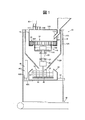
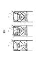
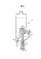
- FIG. 1 is a longitudinal sectional view showing an overall configuration of a foundry sand recycling apparatus according to a first embodiment of the present invention. It is a typical longitudinal section showing a part of process of a foundry sand reproduction method in a 1st embodiment of the present invention.
- 2A shows the first step
- FIG. 2B shows the second step
- FIG. 2C shows the third step.
- FIG. 3A shows a state where water for washing is supplied
- FIG. 3B shows a fourth step
- FIG. 3C shows a state where water for washing is discharged.
- FIG. 4 (A) shows the state of centrifugal dewatering
- FIG. 4 (B) shows the state of sand discharge.
- FIG. 1 is a longitudinal sectional view showing the overall configuration of a foundry sand recycling apparatus 10 according to the first embodiment.
- the vertical direction in the figure is the vertical direction of the foundry sand recycling apparatus 10.
- the foundry sand recycling apparatus 10 includes a box-shaped apparatus main body 10A.
- An upper tank 12 is provided on the inner upper side of the apparatus main body 10A.
- the upper tank 12 includes a cylindrical portion 12A, and a hopper portion 12B is continuously formed at the lower end portion of the cylindrical portion 12A.
- a processing tank 14 is provided in the upper part inside the upper tank 12.
- An intake pipe 14B and an exhaust pipe 14C are connected to the upper wall 14X of the processing tank 14, and the exhaust pipe 14C is connected to a dust collector 50 (illustrated as a block in the drawing).
- the dust collector 50 includes a suction part (blower not shown) for sucking air.
- the intake pipe 14B and the exhaust pipe 14C are provided with a flow rate adjusting gate (not shown). By these, intake / exhaust in the treatment tank 14 and pressure adjustment are possible.
- a sand supply chute 14 ⁇ / b> A is inserted from the outer peripheral side of the side wall 14 ⁇ / b> Y of the treatment tank 14.
- the sand supply chute 14A is used for pouring used casting sand (including core sand).
- the sand supply chute 14A is provided with a flow rate adjusting gate (not shown).
- a rotor 16 as a processing container (processing section) capable of supplying used casting sand is disposed below the sand supply chute 14A.
- the rotor 16 has a bottomed cylindrical shape in which a bottom plate 16A is disposed substantially horizontally, and includes a peripheral wall portion 16B that is erected upward from a peripheral end of the bottom plate 16A.
- the inner space of the rotor 16 constitutes a part of the inner space of the processing tank 14.
- the rotor 16 is provided with a frictional force applying mechanism 18.
- a rotating shaft 22 protruding downward is fixed to the bottom plate 16A of the rotor 16.
- the rotating shaft 22 is rotatably supported by a bearing 24 fixed to the upper tank 12.
- a drive unit 20 (shown in a block form in the drawing) is provided.
- the drive unit 20 rotates the rotating shaft 22 to rotate the rotor 16 about the vertical axis of the apparatus.
- the specific configuration of the drive unit 20 is not illustrated, but the first pulley attached to the lower end side of the rotating shaft 22, the second pulley attached rotatably to the upper tank 12, and the first A belt wound around the pulley and the second pulley, and a motor for rotationally driving the second pulley.
- a clutch is provided between the lower end of the rotating shaft 22 and the drive unit 20. The clutch can be switched between transmission of power of the drive unit 20 and interruption of power of the drive unit 20.
- the frictional force applying mechanism 18 includes a ring portion 26 that is fixed to the upper tank 12 adjacent to the upper end outside of the rotor 16.
- the ring part 26 is disposed with a slight vertical gap between the ring part 26 and the peripheral wall part 16 ⁇ / b> B of the rotor 16, and has a slightly larger inner diameter than the rotor 16.
- the blade 26A is inclined to the side opposite to the rotational direction with respect to the radial direction of the rotor 16 in a plan view of the apparatus. Therefore, the sand that collides with the rotating blade 26A is pushed toward the center of rotation.
- the frictional force applying mechanism 18 applies a frictional force to the sand inside the rotor 16 by rotating the rotor 16.
- a rinsing tank 30 is disposed directly below the upper tank 12 (on the lower side of the rotor 16). That is, the rinsing tank 30 is provided at a position where the sand discharged from the rotor 16 can be received.
- the water washing tank 30 functions as a wet regeneration water tank and a dehydrating rotary tank.
- a water supply / drainage pipe 32 is connected to the water washing tank 30, and the water washing tank 30 can supply and discharge water for washing through the water supply / drainage pipe 32.
- the water supply / drainage pipe 32 passes through a long hole (not shown) extending in the vertical direction formed on the side wall of the apparatus main body 10A.
- a stirrer 34 (agitating blade unit for wet regeneration) is provided in the washing tank 30, a stirrer 34 (agitating blade unit for wet regeneration) is provided.
- the stirrer 34 is connected to the drive unit 20 and can be rotated around the vertical axis of the apparatus, the stirring blade 38 provided around the stirring shaft 36 and disposed inside the washing tank 30, It has.
- the stirring shaft 36 is set coaxially with the rotation shaft 22 (rotation center axis of the rotor 16).
- a clutch is provided between the upper end of the stirring shaft 36 and the drive unit 20. The clutch can be switched between transmission of power of the drive unit 20 and interruption of power of the drive unit 20.
- the stirring blade 38 is a blade having a coarse mesh in this embodiment. Note that a meshless blade may be applied to the stirring blade 38.
- an insole plate portion 42 is connected to the lower end portion of the stirring shaft 36 via a bearing 40.
- the insole plate portion 42 is disposed substantially horizontally inside the flush tank 30.
- the peripheral edge part of the insole board part 42 and the upper-end opening part of the water-washing tank 30 are connected over the perimeter by the stainless steel mesh 44 as a cylindrical net-like body.
- the stainless steel mesh 44 is indicated by a dotted line.
- the mesh of the stainless steel mesh 44 is set to a size that does not allow sand to pass through.
- the washing tank 30 is provided with an elevating mechanism 46 for raising and lowering the washing tank 30 in the vertical direction of the apparatus.
- an elevating mechanism 46 a known elevating mechanism can be applied, but in this embodiment, as an example, a slide part 46A that is attached to the washing tank 30 and can be raised and lowered along the side wall of the apparatus main body 10A, and a slide part 46A is attached to the tip end of the rod 46B1, and the rod 46B1 expands and contracts to raise and lower the slide part 46A.
- a belt conveyor 48 is provided below the apparatus main body 10A.
- the belt conveyor 48 carries out the sand regenerated in the apparatus main body 10A in a predetermined carrying-out direction.
- FIG. 5 shows a process chart showing the process of the foundry sand regeneration cycle.
- the sand crushing step 53 shown in FIG. 5 the lump of sand that has undergone the casting step 51 and the post-treatment step 52 is crushed with a vibrating sieve or the like.
- a magnetic separation process may be performed before the mechanical regeneration step 54.
- unnecessary metal debris is removed using a magnet type device or an eddy current type device.
- the mechanical regeneration step 54 and the water washing (hot water) regeneration step 55 are for removing a binder (for example, a water glass-based inorganic binder) adhering to sand (aggregate) used for mold making and casting. It is this process.
- a binder for example, a water glass-based inorganic binder
- the treated sand is dehydrated or dried to some extent. And the water
- a moisture measuring device such as a resistance type, a microwave type, a near infrared type, a far infrared type, and a heat drying type is applied. Such a measurement is made because it is necessary to determine the amount of water input in making a kneaded material having a constant moisture content.
- the amount of sand required for molding is measured with a weight-type sand weighing machine or a volumetric-type sand weighing machine.
- water is added to the sand.
- water glass is added to give the strength required as a mold.
- a surfactant is added to improve moldability to the mold and to make a foamed mixture.
- a metering pump or the like is used to add these moisture, water glass, and surfactant.
- sand, water glass, and surfactant are uniformly mixed and stirred with a kneader. And it heat-hardens by the blow molding by a compressed air (in the case of a foaming mixture, a press injection molding or a blow molding), etc., and a casting_mold
- template is shape
- the molten metal is poured into a mold by gravity casting, low pressure casting, die casting, or the like to make a casting.
- the casting and the core sand are separated by a vibration sand removal device, an impact sand removal device or the like, and so-called sand removal is performed.
- FIG. 2 is a schematic longitudinal sectional view for explaining the mechanical regeneration step 54 (see FIG. 5).
- used casting sand is supplied (introduced) from the sand supply chute 14A to the rotor 16 (first step).
- the sand is schematically indicated by dots (the same applies to FIGS. 3, 4, and 6 to 9).
- the frictional force applying mechanism 18 applies a frictional force to the sand in the rotor 16 (second step).
- the drive unit 20 of the frictional force applying mechanism 18 rotates the rotor 16 (see arrow a)
- the sand supplied into the rotor 16 is rubbed against each other by centrifugal force on the peripheral wall portion 16B of the rotor 16. It is sequentially deposited on the inner surface side. Further, the sand that exceeds the upper end of the rotor 16 collides with the blade 26A and is returned to the inside of the rotor 16 (see arrow b) to rub against each other, and the aggregated particles become single particles.
- the deposit water glass
- the solubility of the deposit in water is increased.
- a part of is peeled off from the surface of the sand.
- the surface area of the deposit increases as the surface of the deposit becomes rough.
- a clutch (not shown) between the rotating shaft 22 and the drive unit 20 transmits the power of the drive unit 20, and a clutch (not shown) between the stirring shaft 36 and the drive unit 20 is the drive unit 20.
- the power of is cut off.
- the inside of the processing tank 14 is in a negative pressure state by suction from the dust collector 50 (see FIG. 1) side (the suction direction with respect to the processing tank 14 is indicated by an arrow P). For this reason, an air flow into the processing tank 14 is generated between the ring portion 26 and the rotor 16, and sand basically does not flow out from the gap between the rotor 16 and the ring portion 26.
- the sand in the rotor 16 falls into the washing tank 30 on the lower side of the rotor 16 (third step).
- the suction from the dust collector 50 (see FIG. 1) side is stopped, so that the negative pressure state in the treatment tank 14 is released, and the sand flows out from the gap between the rotor 16 and the ring portion 26 ( Sand discharge mechanism).
- the sand that has flowed out travels down the hopper 12B and falls into the washing tank 30 (inside the stainless steel mesh 44) (see arrow z).
- the rinsing tank 30 receives the sand discharged from the rotor 16.
- a processing (so-called batch-type processing) is performed in which a predetermined amount of sand is put into the rotor 16 and processed, and then the processed sand is discharged from the rotor 16. Is adopted.
- FIG. 3 is a schematic longitudinal sectional view for explaining the water washing (hot water washing) type regeneration step 55 (see FIG. 5).
- water for washing is supplied to the washing tank 30 containing sand through a water supply / drain pipe 32 (see arrow c).
- a metering pump, a hot water device, or the like is used for supplying water.
- the water may be room temperature water or warm water.
- the washing tank 30 is filled with an abrasive such as alumina balls.
- the sand in the rinsing tank 30 is washed with water (fourth step).
- a clutch (not shown) between the rotating shaft 22 and the drive unit 20 cuts off the power of the drive unit 20, and a clutch (not shown) between the stirring shaft 36 and the drive unit 20 drives the power of the drive unit 20. introduce.
- the drive part 20 rotates the stirring shaft 36 (refer arrow d)
- attachment on the surface of sand will become an abrasive
- the insole board part 42 connected with the lower end part of the stirring shaft 36 via the bearing 40 (refer FIG. 1) is arrange
- the peripheral end portion of the water washing tank 30 and the upper end opening of the washing tank 30 are connected by the stainless mesh 44 over the entire circumference. For this reason, the sand that has fallen into the rinsing tank 30 is received on the inner periphery side of the stainless steel mesh 44 on the insole plate portion 42. Therefore, when the stirrer 34 is rotated, deposits on the surface of the sand come into contact with the stainless mesh 44 and are scraped off.
- FIG. 4 shows a schematic longitudinal sectional view for explaining the treatment after drainage.
- centrifugal dehydration is performed after drainage.
- a clutch (not shown) between the stirring shaft 36 and the insole plate portion 42 is switched from a state in which the power of the drive unit 20 is cut off to a transmission state, whereby the stirring shaft 36, the stirring blade 38, and the water washing tank 30 is rotated at high speed.
- centrifugal force acts on the sand, and moisture is blown from the sand while the sand is pressed against the stainless mesh 44 side.
- the sand is discharged from the washing tank 30.
- a clutch (not shown) between the stirring shaft 36 and the drive unit 20 is switched from a state where the power of the drive unit 20 is cut off to a state where the power of the drive unit 20 is transmitted, and the stirring blade 38 is rotated.
- the elevating mechanism 46 lowers the washing tank 30 (see arrow f).
- one end of the stainless steel mesh 44 descends together with the rinsing tank 30, so that the sand on the insole plate portion 42 is blown to the outer peripheral side of the insole plate portion 42 by centrifugal force and falls (see arrow g).
- the stainless mesh 44 connects the peripheral end portion of the insole plate portion 42 and the upper end opening of the washing tub 30, the dropped sand passes through the outer periphery side of the stainless mesh 44 and the rinsing tub 30, and the apparatus main body 10 ⁇ / b> A. Are discharged onto a belt conveyor 48 on the lower side of the belt. Then, the belt conveyor 48 carries out the sand regenerated in the apparatus main body 10A in a predetermined carrying-out direction.
- the rotation shaft 22 (rotation center axis of the rotor 16) and the stirring shaft 36 are set on the same axis, and thus the drive unit 20 while saving space.
- the driving force is transmitted from the rotor 16 side and the stirrer 34 side.
- binders and the like attached to the collected used foundry sand can be effectively removed.
- the foundry sand can be used repeatedly in the mold.
- the deposits can be effectively removed from the core sand (providing stable regeneration ability), the hydrophilicity of the regenerated core sand is improved, and the regenerated sand is new sand.
- a foaming agent, water, and a water glass binder By adding an equivalent amount of a foaming agent, water, and a water glass binder, a desired molded product can be obtained in a similar molding time. Therefore, the core sand can be used repeatedly.
- a mechanism air separator for removing fine powder
- an exhaust pipe (not shown) connected to the dust collector 50 (suction part) is connected to the height position between the lower end of the hopper 12B and the upper end of the water washing tank 30 on the side wall of the apparatus main body 10A.
- An air inlet (not shown) may be formed on the opposite side wall of the main body 10A.
- Such a wind power sorting mechanism sorts into a light object separated from sand and a heavy object such as falling sand by applying an air current to the sand discharged from the lower end of the hopper portion 12B. At the same time, it is a mechanism for dropping the heavy object into the washing tank 30.
- the foundry sand regeneration method in such a modification by applying an air flow to the sand dropped from the rotor 16, the light weight separated from the sand and put on the air flow and the falling weight Since the heavy objects are dropped into the washing tank 30 while being sorted into the objects, the deposits separated from the sand can be prevented or suppressed from entering the washing tank 30.
- a vibration sieve for removing sand fine powder and water glass fine powder may be provided on the upper side of the washing tank 30.
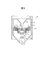
- FIG. 6 the upper part of the foundry sand recycling apparatus 60 is shown in a longitudinal sectional view.
- the foundry sand recycling apparatus 60 does not have a configuration corresponding to the processing tank 14 (see FIG. 1) in the first embodiment, and instead of the upper tank 12 (see FIG. 1), It differs from the foundry sand recycling apparatus 10 (see FIG. 1) according to the first embodiment in that a tank 62 is provided.
- Other configurations are substantially the same as those of the first embodiment. Therefore, components that are substantially the same as those of the first embodiment are denoted by the same reference numerals and description thereof is omitted.
- an upper tank 62 is provided on the inner upper side of the apparatus main body 10 ⁇ / b> A. Since the upper tank 62 has the same configuration as the upper tank 12 (see FIG. 1) in the first embodiment except for the upper configuration, the same components are denoted by the same reference numerals.
- a funnel-shaped sand supply chute 62B is formed from the center of the upper wall 62A of the upper tank 62 toward the lower side.
- the sand supply chute 62 ⁇ / b> B is used for pouring used casting sand, and a lower end opening is disposed above the rotor 16.
- the sand supply chute 62B is provided with a flow rate adjusting gate (not shown).
- foundry sand recycling apparatus 60 and the foundry sand recycling method according to the present embodiment described above, binders and the like attached to the collected used foundry sand can be effectively removed.
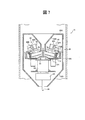
- FIG. 7 the upper part of the foundry sand recycling apparatus 70 is shown in a longitudinal sectional view.
- the foundry sand recycling apparatus 70 is provided with a drum 72 as a processing container (processing unit) instead of the rotor 16 (see FIG. 6) in the second embodiment, and friction.
- a friction force applying mechanism 74 is provided, which is different from the foundry sand recycling apparatus 60 (see FIG. 6) according to the second embodiment.
- Other configurations are substantially the same as those of the second embodiment. Therefore, components substantially the same as those in the first and second embodiments are denoted by the same reference numerals and description thereof is omitted.
- the drum 72 includes a circular bottom plate 72 ⁇ / b> A arranged substantially horizontally, an inclined peripheral wall portion 72 ⁇ / b> B inclined so as to increase in diameter upward from the peripheral end of the bottom plate 72 ⁇ / b> A, and an inclined peripheral wall And a weir portion 72C extending inward from the upper end of the portion 72B.
- the frictional force applying mechanism 74 includes a pair of rollers 76 that are rotatably provided inside the drum 72 and a roller pressurizing mechanism 80 that is provided at the bearing of the roller 76. A part of the outer peripheral surface of the roller 76 is disposed to face the inclined peripheral wall portion 72B with a gap.
- the roller pressure mechanism 80 includes a support arm 80A having a bearing for the roller 76, and a horizontal shaft 80B attached to the support arm 80A and extending in a direction perpendicular to the paper surface of FIG.
- the horizontal shaft 80B can be displaced in a direction in which the roller 76 contacts and separates from the inclined peripheral wall portion 72B by a cylinder (not shown) constituting a part of the roller pressing mechanism 80.
- the roller pressurizing mechanism 80 can pressurize the roller 76 toward the inclined peripheral wall portion 72 ⁇ / b> B, and the friction force is applied to the sand inside the drum 72 by rotating the drum 72 by the driving unit 20. It is a mechanism that gives
- the frictional force imparting mechanism 74 when the drive unit 20 of the frictional force imparting mechanism 74 rotates the drum 72, the sand supplied into the drum 72 is rubbed against each other while centrifugal force is applied to the inclined peripheral wall portion 72B of the drum 72. It is sequentially deposited on the inner surface side of the. Since the sand accumulated on the inner surface side of the inclined peripheral wall portion 72B contacts the roller 76, a frictional force acts on the sand while rotating the roller 76. The part is peeled off from the sand. Thus, the frictional force applying mechanism 74 applies a frictional force to the sand in the drum 72 (second step).
- foundry sand recycling apparatus 70 and the foundry sand recycling method according to the present embodiment described above binders and the like attached to the collected used foundry sand can be effectively removed.
- the first process, the second process, and the third process use the impact type regenerator 90 shown in FIG. 8 and the rotating grindstone regenerator 92 shown in FIG. May be done.
- the impact type regenerator 90 shown in FIG. 8 includes a processing case unit 90A as a processing unit.
- the processing case portion 90A is formed in a three-forked cylinder shape with the lower portion being bifurcated, and is disposed with the vertical direction as the longitudinal direction.
- a sand supply chute 90B is connected to the side of the processing case portion 90A.
- the sand supply chute 90B is a flow path forming part for supplying used casting sand to the processing case part 90A.
- a bifurcated lower portion of the processing case portion 90A includes a first tube portion 90C and a second tube portion 90D. The lower end opening of the first pipe 90C is closed and a nozzle 90E for supplying compressed air is inserted.
- an inner pipe 90F is disposed above the tip of the nozzle 90E with the vertical direction as the longitudinal direction.
- the lower end portion of the inner pipe 90F is disposed at a distance from the tip portion of the nozzle 90E.
- a collision plate 90G is arranged to face the upper end opening of the inner pipe 90F.
- the collision plate 90G is set at a position spaced from the upper end opening of the inner pipe 90F, and is formed of a mesh-like material.
- the mesh of the collision plate 90G is set to a size that allows air to pass and does not allow sand to pass.
- guide portions 90H and 90I are provided inside the processing case portion 90A for guiding sand that has bounced off the collision plate 90G and bounced back to the second pipe portion 90D.
- a washing tank (not shown) is disposed below the second pipe portion 90D.
- the rebound sand is guided by the guide portions 90H and 90I (see arrows A5 and A6), discharged from the downward opening of the second pipe portion 90D, and placed in a water washing tank (not shown) below the processing case portion 90A. Drop (third process).
- the rotary whetstone regenerator 92 includes a processing case unit 92A as a processing unit.
- the processing case portion 92A has a rectangular tube shape with an upper portion extending in the vertical direction, and a lower portion having a semi-cylindrical shape with a horizontal direction (a direction perpendicular to the paper surface of FIG. 9) as an arc center.
- a sand supply chute 92B is connected to the side of the processing case portion 92A.
- the sand supply chute 92B is a flow path forming part for supplying used casting sand to the processing case part 92A.
- Rotating drum 92C is disposed in the lower part of processing case portion 92A.
- an inner cylinder portion 92D and an outer cylinder portion 92E which are arranged coaxially with each other, are connected by a side plate portion 92F, and are driven to rotate clockwise in FIG. 9 (arrow B1). reference).
- a plurality of scraping pieces 92G are provided on the outer peripheral side of the outer cylindrical portion 92E of the rotating drum 92C, and these scraping pieces 92G are arranged side by side in the circumferential direction of the rotating drum 92C.
- a plurality of through holes are formed in the outer cylinder portion 92E and the inner cylinder portion 92D of the rotary drum 92C, and a radially outer side of the outer cylinder portion 92E and a radially inner side of the inner cylinder portion 92D. It has a structure that communicates.
- a cylindrical rotating grindstone 92H is disposed coaxially with the rotating drum 92C on the inner peripheral side of the inner cylinder portion 92D of the rotating drum 92C.
- a gap into which sand or the like enters is formed between the inner periphery of the inner cylindrical portion 92D and the outer periphery of the rotating grindstone 92H.
- the rotating grindstone 92H is driven to rotate in the opposite direction to the rotating drum 92C (see arrow B2).
- a substantially cylindrical discharge pipe 92I for discharging sand and the like inside the processing case portion 92A is connected to the lower portion of the processing case portion 92A.
- a flush tank (not shown) is arranged below the lower end opening 92J of the discharge pipe 92I.
- the rotating shaft 22 and the agitation shaft 36 are set on the same axis, and this is from the viewpoint of making the apparatus compact.
- the net-like body which connects the peripheral edge part of the insole board part 42 and the upper end opening part of the water-washing tank 30 over the perimeter is made into the stainless steel mesh 44
- a net-like body is a synthetic
- Other mesh bodies such as a mesh formed of resin may be used.
- the insole board part 42 and the stainless steel mesh 44 are provided, the structure which these are not provided can also be taken.
- the raising / lowering mechanism 46 is comprised including the air cylinder 46B, it replaces with the air cylinder 46B, and the raising / lowering mechanism like what provided the hydraulic cylinder, what provided the elevator, etc. Other lifting mechanisms may be used. Moreover, the structure which is not provided with an raising / lowering mechanism can also be taken.
- the fourth step may be a step of stirring without adding an abrasive.
- sand or the like in the washing tank may be mixed or stirred using a rotating drum or a kneader.
- the abrasive placed in the washing tank is separated from the sand using a water flow sieve, a vibration sieve or the like.
- a dryer for drying the dehydrated sand a dryer that uses the heat generated when the driving unit of the frictional force applying mechanism rotates the processing container and the stirrer may be installed.
Landscapes
- Engineering & Computer Science (AREA)
- Mechanical Engineering (AREA)
- Molds, Cores, And Manufacturing Methods Thereof (AREA)
- Separation Of Solids By Using Liquids Or Pneumatic Power (AREA)
- Centrifugal Separators (AREA)
- Mold Materials And Core Materials (AREA)
Abstract
Description
また、本発明は以下の詳細な説明により更に完全に理解できるであろう。しかしながら、詳細な説明および特定の実施例は、本発明の望ましい実施の形態であり、説明の目的のためにのみ記載されているものである。この詳細な説明から、種々の変更、改変が、当業者にとって明らかだからである。
出願人は、記載された実施の形態のいずれをも公衆に献上する意図はなく、開示された改変、代替案のうち、特許請求の範囲内に文言上含まれないかもしれないものも、均等論下での発明の一部とする。
本明細書あるいは請求の範囲の記載において、名詞及び同様な指示語の使用は、特に指示されない限り、または文脈によって明瞭に否定されない限り、単数および複数の両方を含むものと解釈すべきである。本明細書中で提供されたいずれの例示または例示的な用語(例えば、「等」)の使用も、単に本発明を説明し易くするという意図であるに過ぎず、特に請求の範囲に記載しない限り本発明の範囲に制限を加えるものではない。
本発明の第1の実施形態に係る鋳物砂再生装置及び鋳物砂再生方法について図1~図5を用いて説明する。図1には、第1の実施形態に係る鋳物砂再生装置10の全体構成が縦断面図にて示されている。図中の上下方向が、鋳物砂再生装置10の上下方向である。
次に、鋳物砂再生装置10を用いた鋳物砂再生方法について図2~図5を用いて説明しながら、上記実施形態の作用及び効果について説明する。
なお、第1の実施形態の変形例として、図1に示される鋳物砂再生装置10のホッパー部12Bの下端と水洗槽30の上端とを装置上下方向に離すと共に、この間を含む範囲に風力選別機構(微粉抜き用のエアセパレータ)を設けてもよい。すなわち、例えば、装置本体10Aの側壁でホッパー部12Bの下端と水洗槽30の上端との間の高さ位置に、集塵機50(吸入部)に繋がる排気管(図示省略)を接続すると共に、装置本体10Aの対向する側壁に吸気口(図示省略)を形成してもよい。このような風力選別機構は、ホッパー部12Bの下端から排出された砂に対して気流を当てることで、砂から分離して気流に乗せられる軽量物と落下する砂等の重量物とに選別すると共に、前記重量物を水洗槽30に落下させるための機構である。
次に、本発明の第2の実施形態に係る鋳物砂再生装置60及び鋳物砂再生方法について、図6を用いて説明する。図6には、鋳物砂再生装置60の上部が縦断面図にて示されている。図6に示されるように、鋳物砂再生装置60には、第1の実施形態における処理槽14(図1参照)に相当する構成がなく、上部槽12(図1参照)に代えて、上部槽62が設けられている点で、第1の実施形態に係る鋳物砂再生装置10(図1参照)とは異なる。他の構成は、第1の実施形態と実質的に同様の構成となっている。よって、第1の実施形態と実質的に同様の構成部については、同一符号を付して説明を省略する。
次に、本発明の第3の実施形態に係る鋳物砂再生装置70及び鋳物砂再生方法について、図7を用いて説明する。図7には、鋳物砂再生装置70の上部が縦断面図にて示されている。図7に示されるように、鋳物砂再生装置70には、第2の実施形態におけるローター16(図6参照)に代えて、処理容器(処理部)としてのドラム72が配置される共に、摩擦力付与機構18(図6参照)に代えて、摩擦力付与機構74が設けられている点で、第2の実施形態に係る鋳物砂再生装置60(図6参照)とは異なる。他の構成は、第2の実施形態と実質的に同様の構成となっている。よって、第1、第2の実施形態と実質的に同様の構成部については、同一符号を付して説明を省略する。
なお、鋳物砂再生方法の他の実施形態として、第一工程、第二工程、及び第三工程は、図8に示される衝撃式再生機90や図9に示される回転砥石再生機92を用いてなされてもよい。
なお、上記第1~第3の実施形態では、図1等に示されるように、回転軸22と攪拌軸36とが、同軸上に設定されており、装置のコンパクト化の観点からはこのような構成が好ましいが、処理容器の回転中心軸と攪拌軸とが同軸上に設定されていない構成とすることも可能である。
10 鋳物砂再生装置
16 ローター(処理容器、処理部)
16A 底板
18 摩擦力付与機構
20 駆動部
22 回転軸(処理容器の回転中心軸)
26 リング部
26A ブレード
30 水洗槽
34 攪拌機
36 攪拌軸
38 攪拌羽根
40 軸受
42 中敷板部
44 ステンレスメッシュ(網状体)
46 昇降機構
60 鋳物砂再生装置
70 鋳物砂再生装置
72 ドラム(処理容器、処理部)
72A 底板
72B 傾斜周壁部
72C 堰部
74 摩擦力付与機構
76 ローラ
80 ローラ加圧機構
90A 処理ケース部(処理部)
92A 処理ケース部(処理部)
Claims (9)
- 使用済みの鋳物用の砂を供給可能な処理容器と、
前記処理容器を装置上下方向の軸回りに回転駆動する駆動部を備え、前記処理容器を回転させることで前記処理容器の内部の砂に摩擦力を付与する摩擦力付与機構と、
前記処理容器の下方側に配置されて水洗用の水を給排水可能とされ、前記処理容器から排出された砂を受け入れる水洗槽と、
前記駆動部に連結されて装置上下方向の軸回りに回転可能な攪拌軸と、前記攪拌軸に設けられて前記水洗槽の内部に配置された攪拌羽根と、を備えた攪拌機と、
を有する鋳物砂再生装置。 - 前記処理容器の回転中心軸と前記攪拌軸とが同軸上に設定されている、請求項1記載の鋳物砂再生装置。
- 前記処理容器は、底板が略水平に配置された有底円筒状のローターとされ、
前記摩擦力付与機構は、前記ローターの上端外側に隣接してかつ装置平面視で前記ローターの半径方向内側に向けて回転する向きと反対側に傾斜した複数のブレードが環状に並設されたリング部を備える、請求項1又は請求項2に記載の鋳物砂再生装置。 - 前記処理容器は、略水平に配置された円形状の底板と、前記底板の周端から上方へ向けて拡径するように傾斜した傾斜周壁部と、前記傾斜周壁部の上端から内側に延設された堰部と、を備えたドラムとされ、
前記摩擦力付与機構は、前記ドラムの内側に回転可能に設けられて外周面の一部が前記傾斜周壁部に対して隙間をもって対向配置されたローラと、前記ローラの軸受けに設けられて前記ローラを前記傾斜周壁部の側に加圧するローラ加圧機構と、を備える請求項1又は請求項2に記載の鋳物砂再生装置。 - 前記水洗槽の内部に略水平に配置され、前記攪拌軸の下端部に軸受を介して連結された中敷板部と、
前記中敷板部の周端部と前記水洗槽の上端開口部とを全周に亘って繋ぐ網状体と、
を有する請求項1~請求項4のいずれか1項に記載の鋳物砂再生装置。 - 前記水洗槽には、前記水洗槽を装置上下方向に昇降させる昇降機構が設けられている、請求項5記載の鋳物砂再生装置。
- 使用済みの鋳物用の砂を処理部に供給する第一工程と、
前記第一工程の後に、前記処理部内の砂に摩擦力又は衝撃力を付与する第二工程と、
前記第二工程の後に、前記処理部内の砂を前記処理部の下方側の水洗槽内に落下させる第三工程と、
前記第三工程の後に、前記水洗槽内の砂を水洗する第四工程と、
を有する鋳物砂再生方法。 - 前記第四工程では、前記水洗槽内の水洗用の水に研磨材が入れられた状態で前記水洗槽内の砂、水及び研磨材が攪拌される、請求項7記載の鋳物砂再生方法。
- 前記第三工程では、前記処理部から落下させた砂に対して気流を当てることで、砂から分離して前記気流に乗せられる軽量物と落下する重量物とに選別すると共に、前記重量物を前記水洗槽に落下させる、請求項7又は請求項8に記載の鋳物砂再生方法。
Priority Applications (4)
| Application Number | Priority Date | Filing Date | Title |
|---|---|---|---|
| CN201390000391.6U CN204657398U (zh) | 2012-06-20 | 2013-04-12 | 铸造砂再生装置 |
| US14/384,312 US10035181B2 (en) | 2012-06-20 | 2013-04-12 | Apparatus and a method for reclaiming foundry sand |
| MX2014012288A MX351768B (es) | 2012-06-20 | 2013-04-12 | Un aparato y un método para recuperar arena de fundición. |
| DE201311001502 DE112013001502T5 (de) | 2012-06-20 | 2013-04-12 | Vorrichtung und Verfahren zur Aufbereitung von Gießereialtsand |
Applications Claiming Priority (2)
| Application Number | Priority Date | Filing Date | Title |
|---|---|---|---|
| JP2012139205A JP5827927B2 (ja) | 2012-06-20 | 2012-06-20 | 鋳物砂再生装置 |
| JP2012-139205 | 2012-06-20 |
Publications (1)
| Publication Number | Publication Date |
|---|---|
| WO2013190888A1 true WO2013190888A1 (ja) | 2013-12-27 |
Family
ID=49768495
Family Applications (1)
| Application Number | Title | Priority Date | Filing Date |
|---|---|---|---|
| PCT/JP2013/061036 Ceased WO2013190888A1 (ja) | 2012-06-20 | 2013-04-12 | 鋳物砂再生装置及び鋳物砂再生方法 |
Country Status (6)
| Country | Link |
|---|---|
| US (1) | US10035181B2 (ja) |
| JP (1) | JP5827927B2 (ja) |
| CN (1) | CN204657398U (ja) |
| DE (1) | DE112013001502T5 (ja) |
| MX (1) | MX351768B (ja) |
| WO (1) | WO2013190888A1 (ja) |
Cited By (6)
| Publication number | Priority date | Publication date | Assignee | Title |
|---|---|---|---|---|
| CN108405798A (zh) * | 2018-03-30 | 2018-08-17 | 常州卡斯特铝精密铸造科技有限公司 | 铝铸造用砂混合转运系统 |
| RU2715138C2 (ru) * | 2015-10-15 | 2020-02-25 | Синтокоджио, Лтд. | Способ регенерации формовочного песка и система регенерации |
| CN111001755A (zh) * | 2019-12-31 | 2020-04-14 | 界首市神机合自动化科技有限公司 | 一种用于铸造砂回收的自动化洗砂设备 |
| CN111760834A (zh) * | 2020-06-29 | 2020-10-13 | 深圳市万城科技有限公司 | 一种节水型智能洗矿设备 |
| CN116099809A (zh) * | 2023-04-14 | 2023-05-12 | 雄县高姿乳胶制品设备技术有限公司 | 一种乳胶手套生产用洗烘一体机 |
| CN116871454A (zh) * | 2023-09-07 | 2023-10-13 | 山西鸿琛锐机械制造有限公司 | 一种型砂的回收处理装置 |
Families Citing this family (15)
| Publication number | Priority date | Publication date | Assignee | Title |
|---|---|---|---|---|
| JP5958966B2 (ja) * | 2013-03-25 | 2016-08-02 | トヨタ自動車株式会社 | 造型装置および造型方法 |
| JP6445333B2 (ja) * | 2015-01-14 | 2018-12-26 | 旭有機材株式会社 | 回収鋳物砂の再生法 |
| JP6445334B2 (ja) * | 2015-01-14 | 2018-12-26 | 旭有機材株式会社 | 回収鋳物砂の再生方法 |
| CN105170899B (zh) * | 2015-10-12 | 2017-10-13 | 嘉善县汾湖铸钢厂 | 一种筒式混砂设备 |
| TW201734450A (zh) * | 2016-03-22 | 2017-10-01 | Sintokogio Ltd | 鑄砂之砂污染度評價方法及砂污染度評價裝置 |
| CN105772627B (zh) * | 2016-03-23 | 2017-11-28 | 侯松涛 | 一种旧砂再生机 |
| CN105772628B (zh) * | 2016-04-22 | 2018-05-01 | 浙江兴盛铸造有限公司 | 一种环保型铸造旧沙翻新装置 |
| CN108031791A (zh) * | 2017-12-14 | 2018-05-15 | 重庆同益机械有限公司 | 一种铸造砂冷却器 |
| CN111408991B (zh) * | 2020-04-03 | 2021-06-04 | 淮北市朗联新型建材有限公司 | 一种干混砂浆砂石原料处理装置 |
| CN113414228B (zh) * | 2021-08-25 | 2021-11-16 | 徐州众迈节能环保科技有限公司 | 一种电磁热熔型钢筋混凝土分离装置及其使用方法 |
| CN113680961B (zh) * | 2021-09-14 | 2023-02-21 | 燕山大学 | 一种搅、冲、脱水一体式水玻璃砂再生系统及方法 |
| CN114951614B (zh) * | 2022-05-20 | 2024-03-08 | 江西鑫航精密铸造有限公司 | 一种铸造设备 |
| CN114951616B (zh) * | 2022-05-20 | 2024-05-24 | 江西鑫航精密铸造有限公司 | 一种铸造砂再生装置 |
| CN117733065B (zh) * | 2023-10-26 | 2024-05-31 | 连云港赣榆腾飞机械铸造有限公司 | 一种铸造覆膜砂回收再生装置及其方法 |
| CN120861744B (zh) * | 2025-09-28 | 2025-11-28 | 河北悦欣新型建材制造有限公司 | 铸造砂水洗控泥装置及方法 |
Citations (7)
| Publication number | Priority date | Publication date | Assignee | Title |
|---|---|---|---|---|
| JPS5630054A (en) * | 1979-08-14 | 1981-03-26 | Tomio Ino | Grinding and washing method for surface of granular material |
| JPH07136735A (ja) * | 1993-11-18 | 1995-05-30 | Kawasaki Heavy Ind Ltd | 鋳物砂再生装置の回転ドラムおよびシエルフリング |
| JPH07314082A (ja) * | 1994-05-25 | 1995-12-05 | Taiyo Chuki Co Ltd | 鋳物砂再生装置 |
| JPH08243682A (ja) * | 1995-03-07 | 1996-09-24 | Hino Motors Ltd | 使用済鋳物砂の再生方法 |
| JP2005177759A (ja) * | 2003-08-21 | 2005-07-07 | Sintokogio Ltd | 機械式再生装置を使用した鋳型砂の再生方法。 |
| JP2006068815A (ja) * | 2004-08-06 | 2006-03-16 | Yamakawa Sangyo Kk | 生型廃砂の再生方法及び鋳型用骨材 |
| JP2009154207A (ja) * | 2007-12-07 | 2009-07-16 | Sintokogio Ltd | 鋳物砂再生装置 |
Family Cites Families (3)
| Publication number | Priority date | Publication date | Assignee | Title |
|---|---|---|---|---|
| JPS5299924A (en) | 1976-02-18 | 1977-08-22 | Hitachi Ltd | Old sand cleaning reproduction process |
| DE4315893A1 (de) * | 1992-07-24 | 1994-11-17 | Boenisch Dietmar | Verfahren und Vorrichtung zum Regenerieren von Gießereisand |
| JP4679718B2 (ja) | 2000-12-15 | 2011-04-27 | 国立大学法人豊橋技術科学大学 | 回収鋳物砂の再生方法 |
-
2012
- 2012-06-20 JP JP2012139205A patent/JP5827927B2/ja active Active
-
2013
- 2013-04-12 US US14/384,312 patent/US10035181B2/en active Active
- 2013-04-12 DE DE201311001502 patent/DE112013001502T5/de not_active Withdrawn
- 2013-04-12 WO PCT/JP2013/061036 patent/WO2013190888A1/ja not_active Ceased
- 2013-04-12 MX MX2014012288A patent/MX351768B/es active IP Right Grant
- 2013-04-12 CN CN201390000391.6U patent/CN204657398U/zh not_active Expired - Lifetime
Patent Citations (7)
| Publication number | Priority date | Publication date | Assignee | Title |
|---|---|---|---|---|
| JPS5630054A (en) * | 1979-08-14 | 1981-03-26 | Tomio Ino | Grinding and washing method for surface of granular material |
| JPH07136735A (ja) * | 1993-11-18 | 1995-05-30 | Kawasaki Heavy Ind Ltd | 鋳物砂再生装置の回転ドラムおよびシエルフリング |
| JPH07314082A (ja) * | 1994-05-25 | 1995-12-05 | Taiyo Chuki Co Ltd | 鋳物砂再生装置 |
| JPH08243682A (ja) * | 1995-03-07 | 1996-09-24 | Hino Motors Ltd | 使用済鋳物砂の再生方法 |
| JP2005177759A (ja) * | 2003-08-21 | 2005-07-07 | Sintokogio Ltd | 機械式再生装置を使用した鋳型砂の再生方法。 |
| JP2006068815A (ja) * | 2004-08-06 | 2006-03-16 | Yamakawa Sangyo Kk | 生型廃砂の再生方法及び鋳型用骨材 |
| JP2009154207A (ja) * | 2007-12-07 | 2009-07-16 | Sintokogio Ltd | 鋳物砂再生装置 |
Cited By (9)
| Publication number | Priority date | Publication date | Assignee | Title |
|---|---|---|---|---|
| RU2715138C2 (ru) * | 2015-10-15 | 2020-02-25 | Синтокоджио, Лтд. | Способ регенерации формовочного песка и система регенерации |
| CN108405798A (zh) * | 2018-03-30 | 2018-08-17 | 常州卡斯特铝精密铸造科技有限公司 | 铝铸造用砂混合转运系统 |
| CN111001755A (zh) * | 2019-12-31 | 2020-04-14 | 界首市神机合自动化科技有限公司 | 一种用于铸造砂回收的自动化洗砂设备 |
| CN111001755B (zh) * | 2019-12-31 | 2020-12-04 | 山东仁合新材料科技有限公司 | 一种用于铸造砂回收的自动化洗砂设备 |
| CN111760834A (zh) * | 2020-06-29 | 2020-10-13 | 深圳市万城科技有限公司 | 一种节水型智能洗矿设备 |
| CN116099809A (zh) * | 2023-04-14 | 2023-05-12 | 雄县高姿乳胶制品设备技术有限公司 | 一种乳胶手套生产用洗烘一体机 |
| CN116099809B (zh) * | 2023-04-14 | 2023-06-06 | 雄县高姿乳胶制品设备技术有限公司 | 一种乳胶手套生产用洗烘一体机 |
| CN116871454A (zh) * | 2023-09-07 | 2023-10-13 | 山西鸿琛锐机械制造有限公司 | 一种型砂的回收处理装置 |
| CN116871454B (zh) * | 2023-09-07 | 2023-11-07 | 山西鸿琛锐机械制造有限公司 | 一种型砂的回收处理方法 |
Also Published As
| Publication number | Publication date |
|---|---|
| JP2014000595A (ja) | 2014-01-09 |
| MX2014012288A (es) | 2014-11-10 |
| DE112013001502T5 (de) | 2015-03-19 |
| MX351768B (es) | 2017-10-26 |
| JP5827927B2 (ja) | 2015-12-02 |
| CN204657398U (zh) | 2015-09-23 |
| US10035181B2 (en) | 2018-07-31 |
| US20150096594A1 (en) | 2015-04-09 |
Similar Documents
| Publication | Publication Date | Title |
|---|---|---|
| JP5827927B2 (ja) | 鋳物砂再生装置 | |
| CN113578510B (zh) | 一种机制砂混凝土用生产系统 | |
| KR20120085730A (ko) | 회전 텀블러 및 금속 리클레이머 | |
| JP2014024097A (ja) | 鋳物砂の再生方法 | |
| JP2005125139A (ja) | プラスチック廃材乾式洗浄装置 | |
| CN101209485A (zh) | 一种旧砂再生方法及其旧砂再生系统 | |
| US4008856A (en) | Reclaiming system for foundry sand | |
| JP4098413B2 (ja) | 砂・粒塊状物の粉砕研磨装置及び鋳物砂の回収再生設備 | |
| JPS6113894B2 (ja) | ||
| JP6445334B2 (ja) | 回収鋳物砂の再生方法 | |
| CZ248194A3 (en) | Process and apparatus for foundry sand regeneration | |
| CN111676521A (zh) | 一种羽绒加工方法及其设备 | |
| KR20010106342A (ko) | 주물사 재생장치 및 그 재생방법 | |
| CN214974784U (zh) | 一种活性炭湿法除杂装置 | |
| CA1149580A (en) | Vibrating reclaimer of foundry mold material | |
| JPH0515964A (ja) | 鋳物砂及び鋳造製品の回収処理装置 | |
| KR100940761B1 (ko) | 골재 세척용 드럼형 세척장치 | |
| CN108296433A (zh) | 一种铸造废砂再生装置 | |
| KR100804140B1 (ko) | 순환골재의 이물질 선별장치 | |
| JPH1059757A (ja) | コンクリ−ト廃材の再生装置 | |
| CA1168640A (en) | Sand lump crushing device | |
| CN113125338A (zh) | 一种透水混凝土骨料与浆体间粘聚力的定量测试装置与测试方法 | |
| CZ133693A3 (en) | Process and apparatus for foundry sand regeneration | |
| CN111438121B (zh) | 一种聚合物砼生态透水砖制备原材料加工处理方法 | |
| CN211330227U (zh) | 一种湿沙初级筛分设备 |
Legal Events
| Date | Code | Title | Description |
|---|---|---|---|
| WWE | Wipo information: entry into national phase |
Ref document number: 201390000391.6 Country of ref document: CN |
|
| 121 | Ep: the epo has been informed by wipo that ep was designated in this application |
Ref document number: 13806988 Country of ref document: EP Kind code of ref document: A1 |
|
| WWE | Wipo information: entry into national phase |
Ref document number: 14384312 Country of ref document: US |
|
| WWE | Wipo information: entry into national phase |
Ref document number: 1120130015021 Country of ref document: DE Ref document number: 112013001502 Country of ref document: DE |
|
| WWE | Wipo information: entry into national phase |
Ref document number: MX/A/2014/012288 Country of ref document: MX |
|
| 122 | Ep: pct application non-entry in european phase |
Ref document number: 13806988 Country of ref document: EP Kind code of ref document: A1 |