WO2014002489A1 - Dispositif de navigation et progiciel de navigation - Google Patents
Dispositif de navigation et progiciel de navigation Download PDFInfo
- Publication number
- WO2014002489A1 WO2014002489A1 PCT/JP2013/003984 JP2013003984W WO2014002489A1 WO 2014002489 A1 WO2014002489 A1 WO 2014002489A1 JP 2013003984 W JP2013003984 W JP 2013003984W WO 2014002489 A1 WO2014002489 A1 WO 2014002489A1
- Authority
- WO
- WIPO (PCT)
- Prior art keywords
- road
- extension
- roads
- navigation device
- moving
- Prior art date
- Legal status (The legal status is an assumption and is not a legal conclusion. Google has not performed a legal analysis and makes no representation as to the accuracy of the status listed.)
- Ceased
Links
Images



Classifications
-
- G—PHYSICS
- G01—MEASURING; TESTING
- G01C—MEASURING DISTANCES, LEVELS OR BEARINGS; SURVEYING; NAVIGATION; GYROSCOPIC INSTRUMENTS; PHOTOGRAMMETRY OR VIDEOGRAMMETRY
- G01C21/00—Navigation; Navigational instruments not provided for in groups G01C1/00 - G01C19/00
- G01C21/26—Navigation; Navigational instruments not provided for in groups G01C1/00 - G01C19/00 specially adapted for navigation in a road network
- G01C21/34—Route searching; Route guidance
- G01C21/36—Input/output arrangements for on-board computers
- G01C21/3667—Display of a road map
- G01C21/367—Details, e.g. road map scale, orientation, zooming, illumination, level of detail, scrolling of road map or positioning of current position marker
-
- G—PHYSICS
- G01—MEASURING; TESTING
- G01C—MEASURING DISTANCES, LEVELS OR BEARINGS; SURVEYING; NAVIGATION; GYROSCOPIC INSTRUMENTS; PHOTOGRAMMETRY OR VIDEOGRAMMETRY
- G01C21/00—Navigation; Navigational instruments not provided for in groups G01C1/00 - G01C19/00
- G01C21/26—Navigation; Navigational instruments not provided for in groups G01C1/00 - G01C19/00 specially adapted for navigation in a road network
-
- G—PHYSICS
- G01—MEASURING; TESTING
- G01C—MEASURING DISTANCES, LEVELS OR BEARINGS; SURVEYING; NAVIGATION; GYROSCOPIC INSTRUMENTS; PHOTOGRAMMETRY OR VIDEOGRAMMETRY
- G01C21/00—Navigation; Navigational instruments not provided for in groups G01C1/00 - G01C19/00
- G01C21/26—Navigation; Navigational instruments not provided for in groups G01C1/00 - G01C19/00 specially adapted for navigation in a road network
- G01C21/34—Route searching; Route guidance
-
- G—PHYSICS
- G01—MEASURING; TESTING
- G01C—MEASURING DISTANCES, LEVELS OR BEARINGS; SURVEYING; NAVIGATION; GYROSCOPIC INSTRUMENTS; PHOTOGRAMMETRY OR VIDEOGRAMMETRY
- G01C21/00—Navigation; Navigational instruments not provided for in groups G01C1/00 - G01C19/00
- G01C21/26—Navigation; Navigational instruments not provided for in groups G01C1/00 - G01C19/00 specially adapted for navigation in a road network
- G01C21/34—Route searching; Route guidance
- G01C21/36—Input/output arrangements for on-board computers
- G01C21/3667—Display of a road map
-
- G—PHYSICS
- G09—EDUCATION; CRYPTOGRAPHY; DISPLAY; ADVERTISING; SEALS
- G09B—EDUCATIONAL OR DEMONSTRATION APPLIANCES; APPLIANCES FOR TEACHING, OR COMMUNICATING WITH, THE BLIND, DEAF OR MUTE; MODELS; PLANETARIA; GLOBES; MAPS; DIAGRAMS
- G09B29/00—Maps; Plans; Charts; Diagrams, e.g. route diagram
- G09B29/10—Map spot or coordinate position indicators; Map reading aids
- G09B29/106—Map spot or coordinate position indicators; Map reading aids using electronic means
Definitions
- the present disclosure relates to a navigation device that learns road sections, a navigation device that displays the current location of the host vehicle on a map, and a program product that displays the current location of the host vehicle on a map.
- Patent Document 1 a road section where the user actually traveled is learned as a road recognized by the user.
- Such a navigation apparatus includes a GPS receiver and generally displays the current location of the host vehicle on a map.
- the user may want information on facilities around the current location, for example, but may want information on intersections in the traveling direction of the vehicle. However, depending on the scale of the map display, the next intersection may not be displayed on the map.
- the second object is to provide a navigation device and a navigation program product that can eliminate the psychological burden of the user as much as possible.
- the navigation device includes a moving road specifying unit, a continuity determining unit, and an extension road setting unit.
- the moving road specifying unit specifies a moving road on which the vehicle has actually traveled by acquiring a current position of the vehicle.
- the continuity determination unit determines whether there is continuity between the first road connected to the end point of the moving road and the moving road.
- the extension road setting unit sets the first road as a first extension road when the continuity determination unit determines that the continuity exists between the first road and the moving road.
- An end point of the moving road is a reference end point
- the moving road is a reference road
- the first road is a determination target road.
- the above navigation device it is possible to learn not only the road section on which the user actually traveled but also the road section with a high probability of being recognized or recognized by the user.
- a navigation device that performs map display that displays the current location of a vehicle in a superimposed manner on a map according to the second aspect of the present disclosure, searches for a route to the destination, and provides route guidance along the route includes: a storage unit; a cognitive road determination unit The cognitive road specifying unit and the switching unit are provided.
- the storage unit stores a plurality of cognitive roads.
- the plurality of cognitive roads include a moving road that is a road on which the vehicle actually travels and an extended road that is a continuous road with respect to the moving road.
- the cognitive road determination unit determines whether roads on which the vehicle is traveling are included in the plurality of cognitive roads based on information on the plurality of cognitive roads stored in the storage unit.
- the cognitive road specifying unit when the cognitive road determination unit determines that the road on which the vehicle is traveling is not included in the plurality of cognitive roads, the plurality of cognitive roads to be displayed on the map.
- the display object recognition road which is one of these is specified.
- the switching unit displays the map so that at least a part of the display target recognition road and the current location of the vehicle are included in one screen. Switch.
- roads that are likely to be recognized by the user are displayed on the map together with the current location, so that the psychological burden on the user can be eliminated as much as possible.
- a navigation program product includes a computer-implemented instruction for realizing the functions of each part of the navigation device according to the second aspect of the present disclosure, and a computer-readable persistent and tangible memory Included in the medium.
- roads that are likely to be recognized by the user are displayed on the map together with the current location, so that the user's psychological burden can be eliminated as much as possible.
- a navigation device that performs map display that displays the current location of a vehicle overlaid on a map according to the fourth aspect of the present disclosure searches for a route to a destination, and provides route guidance along the route includes a storage unit, a cognitive road determination unit And a presentation unit.
- the storage unit stores a plurality of cognitive roads.
- the plurality of cognitive roads include a moving road that is a road on which the vehicle actually travels and an extended road that is a continuous road with respect to the moving road.
- the cognitive road determination unit determines whether roads on which the vehicle is traveling are included in the plurality of cognitive roads based on information on the plurality of cognitive roads stored in the storage unit.
- the presenting unit when the cognitive road determination unit determines that a road on which the vehicle is traveling is not included in the plurality of cognitive roads, the extension road in which the vehicle is included in the plurality of cognitive roads. When approaching, the direction to the position where the moving road exists is presented.
- roads that are likely to be recognized by the user are displayed on the map together with the current location, so that the psychological burden on the user can be eliminated as much as possible.
- a navigation program product includes computer-implemented instructions for realizing the functions of each part of the navigation device according to the fourth aspect of the present disclosure, and a computer-readable persistent and tangible memory Included in the medium.
- roads that are likely to be recognized by the user are displayed on the map together with the current location, so that the user's psychological burden can be eliminated as much as possible.
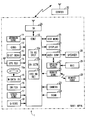
- FIG. 1 is a block diagram illustrating a schematic configuration of a navigation device according to an embodiment of the present disclosure.
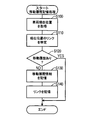
- FIG. 2 is a flowchart showing the movement history storage process.
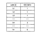
- FIG. 3 is an explanatory diagram showing movement history information.
- FIG. 4 is a flowchart illustrating the extension road setting process according to the first embodiment of the present disclosure.
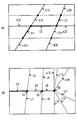
- FIGS. 5A and 5B are explanatory diagrams specifically showing the extension road setting process of the first embodiment.
- FIG. 6 is an explanatory diagram showing the division of the region for optimization of the guidance amount.
- FIG. 7 is a flowchart showing the first half of the extension road setting process of the second embodiment.
- FIG. 8 is a flowchart showing the latter half of the extension road setting process of the second embodiment.
- FIG. 9 is a block diagram illustrating a schematic configuration of a navigation device according to the third embodiment of the present disclosure.
- FIG. 10 is a flowchart illustrating a movement history storage process according to another embodiment of the present disclosure.
- FIG. 11 is a flowchart showing the map display switching process of the third embodiment.
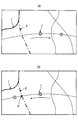
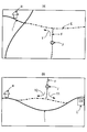
- 12 (a) and 12 (b) are explanatory diagrams specifically showing the map display switching process of the third embodiment.
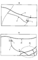
- FIGS. 13A and 13B are explanatory diagrams specifically showing the map display switching process of the third embodiment.
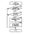
- FIG. 14 is a flowchart showing the direction presentation processing of the third embodiment.
- FIG. 15A and FIG. 15B are explanatory diagrams specifically showing the direction presentation processing.
- a navigation device (NAVI APPA) 1 shown in FIG. 1 is mounted on a vehicle and is configured around a control device (CONT) 10.
- the control device 10 is configured as a so-called computer system, and includes a central processing unit (CPU), a read only memory (ROM), a random access memory (RAM), an input / output interface (I / O), and a bus line connecting these.
- CPU central processing unit
- ROM read only memory
- RAM random access memory
- I / O input / output interface
- the control device 10 includes a geomagnetic sensor (GEOMAGN SENS) 11, a gyroscope (GYRO) 12, a distance sensor (DIST SENS) 13, a GPS receiver (GPS REC) 14, a map data input unit (M-DATA IN) 15, Operation switch group (SWITCH) 16, speed sensor (SPEED SENS) 17, G sensor (G-SENS) 18, external memory (EXT MEMO) 19, display device (DISPLAY) 20, voice controller (AUDIO CONT) 21, remote control sensor (REMOTE SENS) 22, camera (CAMERA) 23, and scanner (SCAN) 24 are connected.
- GEOMAGN SENS geomagnetic sensor
- GYRO gyroscope
- DIST SENS distance sensor
- GPS receiver GPS receiver
- M-DATA IN map data input unit
- SWITCH Operation switch group
- SPEED SENS speed sensor
- G-SENS G sensor
- EXT MEMO external memory
- display device DISPLAY
- voice controller AUDIO CONT
- the geomagnetic sensor 11 is configured to detect the direction of the vehicle by geomagnetism.
- the gyroscope 12 outputs a detection signal corresponding to the angular velocity of the rotational motion applied to the vehicle.
- the distance sensor 13 outputs the travel distance of the vehicle.
- the GPS receiver 14 receives a transmission signal from an artificial satellite for the Global Positioning System (GPS), and detects the position coordinates and altitude of the vehicle.
- GPS Global Positioning System
- the control device 10 can calculate the current location, direction, speed, and the like of the vehicle.
- the method for obtaining the current position based on the output signal from the GPS receiver 14 may be either a single positioning method or a relative positioning method.
- map data input unit 15 is configured to input map data to the control device 10.
- the map data is stored in the DVD-ROM 15 a and is input to the control device 10 via the map data input unit 15.
- an HDD, a CD-ROM, or the like may be used in addition to the DVD-ROM 15a.
- the map data includes road data, drawing data, map matching data, route guidance data, and the like.
- the operation switch group 16 is configured to input various instructions from the user, and is embodied as a physical push button switch or the like. Alternatively, it may be embodied as a touch panel configured integrally with the display device 20.
- the speed sensor 17 is a configuration for detecting the speed of the vehicle.
- the G sensor 18 is a configuration for detecting the acceleration of the vehicle.
- the external memory 19 is embodied as an HDD, for example. In the present embodiment, the movement history is stored in the external memory 19.
- the display device 20 is configured to display a map and various information. Specifically, it is configured using a display device such as a liquid crystal.
- the display device 20 is used for displaying a map image, displaying a guidance route, displaying the current location of the vehicle, and displaying other guidance information.
- the voice controller 21 is configured to control voice and is connected to a speaker (SPEAKER) 26 that outputs guidance voice. Thereby, information is provided to the user together with the display device 20.
- a voice recognition device (SPEECH RECOG) 27 is connected, and a voice signal input through the microphone (MIC) 28 and recognized by the voice recognition device 27 is input. Thereby, various instructions from the user can be input by voice.
- the remote control sensor 22 receives a signal from a remote control terminal (REMOTE CONT) 29 and sends the signal to the control device 10. Thereby, various instructions from the user can be input by remote operation.
- REMOTE CONT remote control terminal
- the camera 23 is configured by a CCD camera or the like, and is a configuration for acquiring a peripheral image of the vehicle.
- the scanner 24 is configured to scan around the vehicle.
- the transceiver (TR) 25 is configured to perform data communication with an external center (CENTER) 30.
- the control device 10 includes a moving road specifying unit (TR RD SPCY) 10a, a continuity determining unit (CN DETM) 10b, and an extended road setting unit (ETD RD SET) 10c.
- TR RD SPCY moving road specifying unit
- CN DETM continuity determining unit
- ETD RD SET extended road setting unit
- a road refers to a unit road in a link unit, and the road is associated with a link.
- the control device 10 acquires the current position of the vehicle. Specifically, the control device 10 acquires the current position of the vehicle using the geomagnetic sensor 11, the gyroscope 12, the distance sensor 13, and the GPS receiver 14 of FIG.
- the control device 10 identifies the link at the current position. This process specifies the link ID corresponding to the current position acquired in S100. In addition, when simply referring to link acquisition or link identification, it means acquisition or identification with a link ID. The same applies to the following.
- the process performed by the control device 10 in S110 functions as the moving road specifying unit 10a.
- the control device 10 determines whether or not there is a movement history. Specifically, the control device 10 determines whether or not there is a movement history based on the movement history information stored in the external memory 19, and once the link has been traveled, it is once traveled as the travel history information. “1” indicating that this has been done is stored. When “1” is stored as the movement history information, the control device 10 determines that there is a movement history in S120. If it is determined that there is a movement history (S120: YES), the control device 10 does not execute the subsequent processing and ends the movement history storage processing. On the other hand, when it is determined that there is no movement record (S120: NO), the control device 10 proceeds to S130.
- control device 10 stores the movement history information. Specifically, the control device 10 stores “1” as the movement history information for the link acquired in S110.
- control device 10 stores the link. Specifically, the control device 10 stores the newly traveled link by storing the link newly storing “1” as the movement history information in S130.
- movement history information as shown in FIG. 3 is stored corresponding to the link. “1” indicating that the vehicle has traveled once is stored as the travel history information of the links L1, L2, and L3 that have actually traveled, and the travel history information of the link Ln that has not yet traveled has not yet traveled. “0” representing is stored. Further, the movement history information of the link Lm related to the link whose movement history information is “1” is “2” indicating that the road is an extension road.
- This extended road setting process is executed by the control device 10 at the timing when the ignition (IG) switch is turned on.
- the process execution timing is not limited to this.
- the control device 10 acquires a link. Specifically, the control device 10 acquires one of the plurality of links stored in S140 in FIG.
- the control device 10 acquires a link connected to the link end point. Specifically, the control device 10 acquires one of the links connected to the end point of this link based on the link acquired in S200.
- the control device 10 determines whether guidance at the connection point is necessary. Specifically, the control device 10 determines whether or not guidance is required at the connection point between the link (moving road) that is the basis and the link (first road) acquired in S210.
- the connection point that connects the base link and the link acquired in S210 is also referred to as the reference end point
- the base link is also referred to as the reference road
- the link that connects to the base link and the connection point is the determination target road.
- control device 10 acquires a road name. This process acquires the road name of the link acquired in S200 and the link acquired in S210.
- the control device 10 determines whether or not the road names match. For example, in the case of roads in Japan, it is determined whether or not both the road type such as “National road” and “Prefectural road” and the numbers such as “No. 1” and “No. 10” match. If it is determined that the road names match (S240: YES), the control device 10 sets the first road as the determination target road as the first extension road in S250, and the extension is performed in S260. A link (second road) connected to the link end point of the road is acquired, and then the processing from S220 is repeated. For example, if the second road that is the determination target road satisfies the name condition, it is set as the second extension road.
- the control device 10 determines whether there is another connection link. Specifically, the control device 10 determines whether there is another link connected to the link acquired in S200. Here, when the control device 10 determines that there is another connection link (S270: YES), the processing from S210 is repeated. Thereby, another link connected to the link acquired in S200 is acquired. On the other hand, when the control apparatus 10 determines that there is no other connection link (S270: NO), the process proceeds to S280.
- the control device 10 determines whether there is an unprocessed link. Specifically, the control apparatus 10 determines whether there is an unprocessed link among the links stored in S140 in FIG. If the control device 10 determines that there is an unprocessed link (S280: YES), the processing from S200 is repeated. On the other hand, when determining that there is no unprocessed link (S280: NO), the control device 10 ends the extension road setting process.
- links actually traveled are designated as links L1, L2, and L3.
- “1” is stored as the movement history information for the links L1, L2, and L3 (S130 in FIG. 2).
- the links L1, L2, and L3 are stored as newly traveled links (S140).
- the extended road setting process it is determined whether or not guidance is necessary at the connection point (S220 in FIG. 4). If it is determined that guidance is not necessary (S220: NO), for example, if the road is a road, (S230) If the road names match (S240: YES), an extension road is set (S250). Then, the same processing is performed for the link connected to the extension road (S260). Therefore, in FIG. 5A, as shown by the broken line, the extended roads E11, E12, E13,... Are set on the condition that the road name is the same as the link L1 and the road names match. Further, the extension roads E21, E22,... Are set on the condition that the road name matches the link L2 and the road names match. Furthermore, extension roads E31, E32, E33,... Are set on the condition that the road name matches the link L3 and the road names match.
- a link L4 with a movement record is acquired (S200 in FIG. 4), and any of the links L5, L6, and L7 connected to the link end point T4 is acquired. (S210).
- S220: YES guidance is necessary because it is not a road
- S220: NO the road name of the link L5 is acquired (S230), and the road name matches the link L4 (S240).
- S250 the broken line
- any of the links L8, L9, and L10 connected to the end point T5 of the link L5 that is an extended road is acquired (S260), and the same processing is performed.
- any of the links L11, L12, L13, L14, L15, and L16 connected to the end point T8 of the link L8 is acquired (S260).
- S220: YES guidance is necessary for any of the links L11 to L16
- S240: NO the setting of the extension road based on the link L4 is terminated.
- the intersection when it is determined that guidance is necessary, it includes a case where the intersection has dedicated guidance data because it is a difficult intersection even on a road. For example, as shown in FIG. 5 (b), even if the link L11 is connected to the link L8 along the road, there are many links connected to the end point T8 (L11 to L16), and the determination of the road or road is lost. This corresponds to the case where dedicated guidance data is prepared at the end point T8 when there is a possibility of possibility.
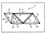
- an area along the actually traveled link (link indicated by a solid line) is defined as area A
- an area along the extended road link (link illustrated by a broken line) is defined as area B.
- a closed region surrounded by the region A is referred to as a region A1
- a closed region surrounded by the region B or surrounded by the region B and the region A is referred to as a region B1.
- the other area is referred to as area C.
- the area A1 and the area B are less likely to be recognized by the store than the area A. However, it is an area where promotion to the area A (expansion of the user's action range) can be expected in the future because it has a land intuition and is easy to access compared to the area C. For this reason, it is conceivable to provide information with an emphasis on highly reusable information. For example, information such as a store that matches a user's preference that is likely to become a new favorite store and a popular menu for each store is searched and provided.
- control device 10 includes a moving road specifying unit 10a, a continuity determining unit 10b, and an extension road setting unit 10c.
- the moving road specifying unit 10a acquires the current position of the vehicle (S100 in FIG. 2) and specifies the moving road on which the vehicle actually traveled (S110).
- the continuity determination unit 10b determines whether there is continuity of the road connected to the end point of the moving road specified by the moving road specifying unit 10a (S220 and S240 in FIG. 4). Then, the extension road setting unit 10c sets the road determined to be continuous by the continuity determination unit 10b as an extension road (S250).
- the navigation device 1 determines the presence or absence of continuity with the actually traveled road and sets an extension road. Thereby, it is possible to learn not only a road section where the user actually traveled but also a road section with a high probability of being recognized by the user.
- a link connected to the link end point of the first extension road is acquired (S260), and the presence or absence of continuity is similarly determined. Judgment is made (S220, S240), and a further extension road (second extension road) is set (S250). That is, the continuity determination unit 10b determines whether there is continuity of the road connected to the end point of the extension road opposite to the moving road, and the extension road setting unit 10c determines whether the continuity determination unit 10b has continuity.
- the road judged to be present is set as a further extension road. Thereby, the road connected to the extension road is set as a further extension road, and a highly probable road section recognized by the user can be learned.
- the number of times of acquiring a link connected to the link end point of the extension road may be limited.
- the number of times the link is acquired may be one time or may be one or more times.
- the number of times may be set larger as the road width is larger, or in the case of the number of lanes, the number of times may be increased as the number of lanes increases.
- the presence / absence of continuity is determined based on whether or not guidance is necessary at the connection point between the reference road, which is the underlying link, and the determination target road connected to the underlying link (S220 in FIG. 4). ), When guidance is unnecessary (S220: NO), it is assumed that there is continuity. That is, the continuity determination unit 10b determines that there is continuity when guidance at an end point is unnecessary. As a result, since the road that is basically a road is an extension road, an appropriate extension road can be set.
- the presence or absence of continuity is determined by whether or not the road names match (S240 in FIG. 4). If the road names match (S240: YES), it is assumed that there is continuity. . That is, the continuity determination unit 10b determines that there is continuity when the names of both roads connected at the end points at least partially match. Thereby, since the road with the same road name is made into an extension road, an appropriate extension road can be set.
- the travel history information (TRV INFO) of the actually traveled link is “1” indicating travel
- the travel history information of the extended road link is “2” indicating the extended road.
- the navigation device 1 according to the second embodiment of the present disclosure will be described with reference to FIGS. 7 and 8.
- the extended road setting process of the above embodiment executed by the control device 10 is different. Therefore, the extension road setting process executed by the control device 10 according to the present embodiment will be described with reference to FIGS.
- This extended road setting process is executed by the control device 10 at the timing when the IG switch is turned on, similarly to the extended road setting process according to the first embodiment.
- the process execution timing is not limited to this. Since there are processes added to the extended road setting process of the above-described embodiment, these processes will be mainly described.
- the control device 10 After acquiring the link in the first S200, the control device 10 acquires the road type, road width, and number of lanes in subsequent S300. This process acquires information related to the road scale of the link acquired in S200.
- the control device 10 determines the maximum number N of connections based on the road type, road width, and number of lanes acquired in S300.
- the variable n is initialized to 1.
- the maximum number N of connections indicates how far an extension road is set when it is determined that guidance is necessary at a connection point from the underlying link. That is, the maximum number of connections N determines the set number of times when setting a plurality of extension roads.
- control device 10 acquires a road name. This process is the same as S230 in FIG.
- the control device 10 determines whether or not the road names match. This process is the same as S240 in FIG. When the control device 10 determines that the road names match (S410: YES), the control device 10 proceeds to S420. On the other hand, when the control device 10 determines that the road names do not match (S410: NO), the control device 10 proceeds to S470 in FIG. In addition, when there is no road name, it shall be regarded as a match.
- the control device 10 determines whether guidance is necessary at the connection point. This process is the same as S220 in FIG. When determining that guidance is necessary (S420: YES), the control device 10 proceeds to S430 in FIG. On the other hand, when determining that the guidance is unnecessary (S420: NO), the control device 10 proceeds to S450 in FIG. In the present embodiment, the processing performed by the control device 10 in S410 and S420 functions as the continuity determination unit 10b.
- control device 10 increments the variable n.
- control device 10 determines whether or not the variable n is larger than the maximum connection number N.
- n> N here S440: YES
- the control device 10 proceeds to S470.
- n ⁇ N S440: NO
- the control device 10 proceeds to S450.
- control device 10 sets an extension road, acquires a link connected to the link end point of the extension road in S460, and then repeats the processing from S400.
- the processes of S450 and S460 are the same as S250 and S260 in FIG. In this embodiment, the process performed in S450 functions as the extension road setting unit 10c.
- the control device 10 determines whether or not there is another connection link, similar to S270 in FIG. Specifically, the control device 10 determines whether there is another link connected to the link acquired in S200. When it is determined that there is another connection link (S470: YES), the control device 10 repeats the processing from S210 in FIG. On the other hand, when determining that there is no other connection link (S470: NO), the control device 10 proceeds to S480.
- the control device 10 determines whether there is an unprocessed link. When determining that there is an unprocessed link in S480 (S480: YES), the control device 10 repeats the processing from S200 in FIG. On the other hand, when determining in S480 that there is no unprocessed link (S480: NO), the control device 10 ends the extension road setting process.
- the maximum number of connections N is set. If not exceeded (S440 in FIG. 8: NO), the link is to be set as an extension road (S450). At this time, the maximum number N of connections is determined by the road type, road width, and number of lanes of the underlying link (S300, S310).
- the maximum number of connections N is determined (S310 in FIG. 7), and as long as the variable n does not exceed the maximum number of connections N (S440: NO in FIG. 8), guidance is required.
- an extension road is set (S450). That is, the extension road setting unit 10c sets a further extension road using the maximum number of connections together with the determination of the continuity determination unit 10b. That is, for example, even if it is a road that is not a road, that is, a road that requires a right or left turn, a road that has a high probability of being recognized is set as an extension road. Thereby, the setting of an appropriate extension road is implement
- the maximum number of connections N is set based on the road type, road width, and number of lanes of the moving road (S300, S310 in FIG. 7). That is, the extension road setting unit 10c sets the maximum number N of connections according to the scale of the moving road. Thereby, since the maximum number of connections is appropriately determined, an extension road is set within an appropriate range.
- the navigation device 1 according to the third embodiment of the present disclosure will be described with reference to FIGS. 9 and 11 to 15B. Since the navigation device 1 according to the present embodiment is different only in the switching of the map display on the display device 20, the description of the configuration and the like is omitted.
- the control device 100 of the navigation control device 1 includes a recognition road determination unit (RCG RD DETM) 100a, a recognition road identification unit (RCG RD SPCY) 100b, a switching unit (SW) 100c, and a presentation unit (NOTIFY) 100e.
- RCG RD DETM recognition road determination unit
- RCG RD SPCY recognition road identification unit
- SW switching unit
- NOTIFY presentation unit
- the external memory 19 stores a recognized road that is a road that is highly likely to be recognized by the user.
- This map display switching process executed by the control device 100 will be described based on the flowchart of FIG.
- This map display switching process is repeatedly executed with the ignition (IG) switch turned on and the map display on the display device 20 of the navigation device 1 being performed.
- IG ignition
- the control device 100 determines whether or not the road on which the vehicle is currently traveling is a recognized road that is likely to be recognized by the user. That is, the control device 100 determines whether the road on which the vehicle is currently traveling is included in the recognition road including the moving road and the extension road stored in the external memory 19. Here, an affirmative determination is also made when the vehicle leaves the moving road. If the control device 100 determines that the road on which the vehicle is currently traveling is a cognitive road (S500: YES), the control device 100 ends the map display processing without executing the subsequent processing. On the other hand, when the control device 100 determines that the road on which the vehicle is currently traveling is not a recognition road (S500: NO), the control device 100 proceeds to S510.
- the process performed in S500 for determining whether the road on which the vehicle is currently traveling is a cognitive road functions as the cognitive road determination unit 100a.
- the control device 100 determines whether or not the navigation device 1 is performing route guidance.
- the control device 100 makes a positive determination when a route search is performed in the navigation device 1 and route guidance based on the route is performed.
- the control device 100 determines that the navigation device 1 is performing route guidance (S510: YES)
- the control device 100 proceeds to S520.
- the control device 100 determines that the navigation device 1 is not in route guidance (S510: NO)
- the control device 100 proceeds to S530.
- the control device 100 determines whether there is a recognition road around the destination. Specifically, the control device 100 determines whether or not there is a cognitive road within a range of a predetermined radius M meters (m) centered on the destination, for example.
- the control device 100 proceeds to S540.
- the recognition road around the destination is also called the first recognition road.
- the recognition road (first recognition road) around the destination is the display target recognition road that is the target of the map display.
- the subsequent processing is not executed and the map display switching processing is terminated.
- the control device 100 searches for the nearest cognitive road. Specifically, the control device 100 searches for a cognitive road that is closest in distance from the current location of the host vehicle.
- the nearest recognition road is located forward in the traveling direction of the host vehicle
- the road distance in the traveling direction of the host vehicle is calculated by multiplying the actual distance by a coefficient p (0 ⁇ p ⁇ 1).
- the cognitive road with the shortest distance from the current location of the vehicle is also referred to as the second cognitive road.
- the cognitive road (second cognitive road) that is the closest in distance from the current location of the host vehicle is the display target cognitive road that is the target of the map display.
- the control device 100 determines whether or not the display target recognition road is within a predetermined distance from the current location. Specifically, the control device 100 determines whether or not the distance from the current location to the display target recognition road is within a predetermined distance L meters (m). When it is determined that the display target recognition road is within the predetermined distance (S540: YES), the control device 100 proceeds to S550. On the other hand, when determining that the display target recognition road is not within the predetermined distance (S540: NO), the control device 100 ends the map display switching process without executing the subsequent processes.
- the control device 100 controls the display device 20 to switch to a map display including at least a part of the display target recognition road. Specifically, the control device 100 automatically changes the scale of the map to a scale that includes a part of the current location and the display target recognition road, adjusts the display position (display area) of the host vehicle, A part of the current location and the display target recognition road is included in one screen.
- the control device 100 determines whether or not there is a switching instruction. Specifically, the control device 100 determines a switching instruction from the user via the operation switch group 16 of FIG. A part of the display target recognition road is displayed by the map display switching process of S550, but when the user desires a map display of a wider area, the user himself / herself issues a switching instruction.
- the control device 100 performs map display including at least a part of the moving road in S570, and thereafter ends the map display switching process.
- the control device 100 ends the map display switching process without executing the process of S570.
- the processing performed by the control device 100 in S550 and S570 functions as the switching unit 100c.
- the host vehicle J is traveling in the direction of the arrow. It is assumed that the host vehicle J is traveling on a road that the user does not know and route guidance to the destination indicated by the symbol G is performed.
- the control device 100 determines that there is no cognitive road around the destination G (S510: YES, S520: NO in FIG. 11), and switches to a map display including a part of the cognitive road ( S550) is not performed. In other words, even if there is a recognized road near the departure point, for example, even if it has left the recognized road, if there is no recognized road around the destination, the control device 100 does not switch the map display.
- FIG. 12B there are a moving road I and an extension road E as cognitive roads ahead. That is, a recognition road exists around the destination G. Therefore, the control device 100 determines that a recognition road exists around the destination (S510: YES, S520: YES in FIG. 11), and the road distance to the point P of the extension road E is within a predetermined distance. (S540: YES), switching to map display including at least a part of the recognition road is performed (S550). That is, when there is a recognized road around the destination, the control device 100 switches the map display and displays a road that has a high possibility of being recognized together with the current location.
- FIGS. 13 (a) and 13 (b) show a situation where the host vehicle J has left the cognitive roads R and R1. Here, it is assumed that route guidance is not performed.
- the control device 100 searches for the closest recognition road R (S530). . Specifically, the determination is based on the distance to the point P where the vehicle left.
- the control device 100 switches to a map display including at least a part of the recognized road R (S550). In this case, a part of the recognition road R is displayed, and a guide road F from the current location to the recognition road R is displayed (S550). That is, when the vehicle leaves a road that has a high possibility of being recognized, the road and the return route to the road are displayed on the map.
- the control device 100 searches for the closest recognition road R2 (S530).
- the recognition road R2 includes a plurality of recognition roads.
- the travel distance in the traveling direction of the host vehicle J is calculated by multiplying the actual distance by the coefficient p (0 ⁇ p ⁇ 1).
- the control device 100 calculates the road distance by multiplying the road distance to the point P by the coefficient p.
- the control device 100 switches to a map display including at least a part of the recognition road R2 (S550).
- a part of the recognition road R2 is displayed and a guide road F to the recognition road R2 is displayed (S550).
- the other road and the road that leads to that road will be displayed on the map. It is displayed.
- the control device 100 controls the display device 20 to display the display target recognition road and the guide road displayed on the map in a manner recognizable to the user. For example, it is displayed in a different color from other roads. For example, the display target recognition road and the guide road are highlighted (inverted) or blinked (flashed). Note that the display target recognition road and the guide road may be displayed in a distinguishable manner, or the moving road and the extension road may be displayed in a distinguishable manner among the display target recognition roads.
- the scale is changed so that at least a part of the moving road is included. Therefore, the scale is changed at indefinite intervals. Specifically, when the scale change at a fixed interval on a normal map is changed in ascending order such as 100 m, 200 m, 400 m, 800 m, 1.6 km (km), the scale is changed from 400 m to 1 in S570. Change to .6km. That is, the scale is changed at indefinite intervals in the positional relationship between the current location and the moving road. In addition, although the switching display of S550 is automatically performed, the scale change is also performed at an indefinite interval in the positional relationship between the current location and the display target recognition road.
- This direction presentation processing is executed by the control device 100 following the map display switching processing of FIG. 11 when route guidance is not performed.
- the control device 100 determines whether or not the guide road is connected to the extension road. Specifically, the control device 100 determines whether or not the above-described guide road is connected to an extension road among the moving road and the extension road constituting the display target recognition road. When the control device 100 determines that the guide road is connected to the extension road (S600: YES), the control device 100 proceeds to S610. On the other hand, when it is determined that the guide road is not connected to the extension road (S600: NO), the control device 100 ends the direction presentation process without executing the subsequent processes.
- the control device 100 determines whether or not the own vehicle has approached the extension road.
- the control device 100 determines whether or not the vehicle has approached the extended road by determining whether the distance from the host vehicle to the intersection of the guide road and the extended road is below a predetermined threshold, for example, 50 m. .
- a predetermined threshold for example, 50 m.
- the control device 100 proceeds to S620.
- the control device 100 does not perform the subsequent processing and ends the direction presentation processing.
- the control device 100 presents the direction to the moving road. Specifically, the control device 100 presents the direction to the position where the moving road exists with respect to the extended road to which the guide road connects. For example, if there is a moving road on the left side of the extension road, the user is notified that there is a moving road on the left side.
- control device 100 displays a facility having a large number of stop-by times. Specifically, the control device 100 displays, for example, an icon on a map of a facility with a large number of visits such as a home or a company.
- the processing performed by the control device 100 in S620 and S630 functions as the presentation unit 100e.
- FIG. 15A and FIG. 15B show a state where the host vehicle J heads from the guide road F to the extension road E. Here, it is assumed that route guidance is not performed.
- the control device 100 determines that the guide road F is connected to the extension road E (S600: YES in FIG. 14), and determines whether or not the extension road E is approached. Judgment is made (S610).
- the control apparatus 100 judges that it has approached the extension road E (S610: YES), it will show the direction to the moving road I (S620).
- the control device 100 controls the display device 20 to present the direction to the moving road I with an arrow.
- the direction to the moving road I may be presented by voice.
- the control device 100 displays the facility with a large number of times of visiting with icons (S630). For example, as indicated by the symbol H in FIG.
- the moving road I is connected from the home indicated by the symbol H to the company indicated by the symbol C via, for example, a highway.
- the control device 100 determines that the guide road F is connected to the extension road E (S600: YES in FIG. 14), and determines whether or not the extension road E is approached. (S610). If it is determined that the vehicle has approached the extension road E (S610: YES), the control device 100 presents a direction to the moving road I (S620). In the case of FIG. 15B, since there are moving roads in the left direction and the right direction, both the left and right directions should be presented as directions to the moving road I as indicated by symbols Y1 and Y2. Can be considered.
- the control device 100 displays the facility with a large number of times of visiting with icons (S630). For example, as shown by symbols H and C in FIG. 15B, a home icon and a company icon are displayed.
- the control device 100 includes the recognition road determination unit 100a, the recognition road identification unit 100b, and the switching unit 100c.
- the external memory 19 as the “storage unit” stores a plurality of recognized roads that are highly likely to be recognized by the user.
- the recognition road determination unit 100a of the control device 100 determines whether or not the road on which the vehicle is traveling is a recognition road based on the information stored in the external memory 19 (S500 in FIG. 11).
- the cognitive road identifying unit 100b identifies the display target cognitive road that is the target of map display when the cognitive road determining unit 100a determines that the road on which the vehicle is traveling is not a cognitive road (S500: NO). (S520, S530).
- the switching unit 100c switches to a map display in a mode in which at least a part of the display target recognition road and the current location are included in one screen (S550, S570).
- the recognition road which is a road that is likely to be recognized by the user, is memorized, and when it deviates from the recognition road, at least a part of the display recognition road is displayed together with the current location on one screen. It was. Thereby, since a road with a high possibility of being recognized by the user is displayed together with the current location on the map, the psychological burden on the user can be eliminated as much as possible.
- the navigation device 1 determines whether or not route guidance is performed by the navigation device 1 (S510 in FIG. 11), and when the route guidance is performed (S510: YES), it is recognized around the destination. It is determined whether there is a road (S520). When there is a recognition road (first recognition road) around the destination (S520: YES), the recognition road is set as a display target recognition road that is an object of map display. That is, when the route guidance is being performed, the recognized road specifying unit 100b specifies the recognized road as a map display target when there is a recognized road around the destination.
- the map display is switched (see FIG. 12B). For example, a recognition road that has a high possibility of being recognized at an early stage, such as a return from leisure or a return from a first business trip, is displayed on the map. Thereby, a user's psychological burden can be reduced.
- the map display is not switched under a situation where the user goes from a known location to an unknown location (see FIG. 12A).
- the route guidance is not performed (S510: NO), such as when the user leaves the cognitive road (S500: NO in FIG. 11)
- the nearest cognitive road is selected.
- a search is performed (S530), and the map is displayed. That is, when route guidance is not performed, the recognized road specifying unit 100b searches for a recognized road having a small distance from the current location, and specifies the recognized road as a display target recognized road that is a target of map display. That is, in a situation where the road is a little away from the known road, the map display is switched to display the closest cognitive road (see FIG. 13A). Thereby, a user's psychological burden can be reduced.
- the travel distance in the traveling direction of the host vehicle is calculated by multiplying the actual distance by a coefficient p (0 ⁇ p ⁇ 1).
- the cognitive road specifying unit 100b corrects the distance to the cognitive road in the traveling direction of the vehicle to be smaller than the actual distance.
- the cognitive road in the traveling direction of your vehicle is searched as the closest cognitive road, and the map display is switched. (See FIG. 13B). Thereby, a user's psychological burden can be reduced.
- the recognition roads R and R1 leave S500: NO, S510: NO in FIG. 11
- the nearest recognition roads R and R2 are searched (S530), and the recognition roads R and R2 are searched.
- the map display including a part of the map S550
- the guide road F to the recognition roads R and R2 is also displayed (S550).
- the switching unit 100c switches to a map display in a mode that includes a guide road that is a road from the current location to the recognized road, in addition to at least a part of the recognized road and the current location. Thereby, a user's psychological burden can further be reduced.
- the guide road F when it is determined that the guide road F is connected to the extension road E (S600: YES in FIG. 14), it is determined whether or not the extension road E is approached (S610). If it is determined that the vehicle has approached the extension road E (S610: YES), the direction of the moving road I is presented (S620). For example, as shown by symbols Y, Y1, and Y2 in FIGS. 15A and 15B, the direction of the moving road I is presented by an arrow. That is, when the cognitive road determination unit 100a determines that the cognitive road is not traveling, the presentation unit 100 presents the direction in which the moving road exists when approaching the extension road that constitutes the cognitive road. Thereby, the user's psychological burden when approaching the extension road from the guide road can be reduced.
- the presentation unit 100e displays facilities with a large number of visits with icons (S630 in FIG. 14). For example, as shown by symbols H and C in FIGS. 15A and 15B, the presentation unit 100e displays home and company icons. That is, the presentation unit 100e displays on the map facilities that have frequently visited in the past. Thereby, a user's psychological burden can further be reduced.
- the recognition roads R and R2 and the guide road F displayed on the map are displayed in a manner that can be recognized by the user by changing the color, for example. That is, the switching unit 100c switches to a map display in which the recognition road and the road related to the recognition road can be distinguished from other roads. Thereby, the map display becomes easy to understand, and in this sense, the user's psychological burden can be further reduced.
- the control device 100 determines whether or not the recognized road is within a predetermined distance (S540 in FIG. 11). When determining that the recognized road is within the predetermined distance (S540: YES), the control device 100 switches to a map display including a part of the recognized road (S550). That is, the switching unit 100c of the control device 100 determines the map display switching timing according to the distance from the current location to the recognition road. Thereby, the map display is switched at an appropriate timing.
- the control device 100 determines whether or not there is a switching instruction from the user (S560 in FIG. 11).
- the control device 100 switches to a map display including a part of the moving road (S570). That is, the switching unit 100c of the control device 100 determines the map display switching timing according to the switching instruction from the user. Thereby, the map display is switched at a timing desired by the user.
- the user himself / herself issues a switching instruction (S560 in FIG. 11: YES), thereby switching the map display (S570). That is, when there is a switching instruction from the user, the switching unit 100c switches to a wider map display.
- the scale is changed to include at least a part of the moving road (display target recognition road), and the scale is changed at indefinite intervals.
- the control device 100 automatically changes the scale to include a part of the current location and the recognition road, adjusts the display position (display area) of the own vehicle, and adjusts the current location and the recognition road. Is included in one screen (S550, S570). That is, the switching unit 100c of the control device 100 switches to map display in a mode in which at least a part of the recognized road and the current location are included in one screen by switching at least one of the scale of the map and the display area. As a result, the map display can be switched relatively easily.
- the control device 100 identifies a moving road that is the road on which the vehicle actually traveled, and stores it in the external memory 19 as movement history information (see FIG. 2). That is, the recognition road includes a moving road that is a road on which the vehicle actually travels. This increases the possibility that the recognition road is a road recognized by the user.
- the control device 100 further includes a learning unit (LEARN) 100d that learns a road having continuity with a moving road as an extension road (FIG. 4, S250).
- An extension road is included. Thereby, a recognition road turns into a road with high probability which a user can recognize.
- the link corresponding to the current position acquired in S100 is specified (S110).
- the continuity determination unit 10b may determine that there is continuity when the names of the roads connected at the end points are at least partially matched. In this way, it is possible to flexibly determine the matching of road names.
- the “proper noun part” may be determined. That is, on the assumption that the proper noun part is included in the name of the road, the continuity determination unit 10b may determine that there is continuity when the proper noun part matches. By determining the matching of the proper noun parts, it is possible to flexibly determine the matching of the road names.
- road names are composed in the format of [Prefix] + [Body] + [Street Type] + [Suffix].
- the proper noun part corresponds to [Body]. Therefore, when the [Body] part is matched, it may be determined that the road names are matched.
- W MAIN ROAD is composed of [Prefix] + [Body] + [Street Type].
- 5TH5AVE SE is configured by [Body] + [Street Type] + [Suffix].
- CA-10 is composed only of [Body].
- the character string match determination may be based on notation fluctuation. That is, the continuity determination unit 10b may consider the shaking of the notation in determining whether the road names match. For example, “1st” and “First” are handled as the same character string. For example, “W” and “West” are treated as the same character string, and “ST” and “street” are treated as the same character string. In this way, it is possible to more flexibly determine matching of road names.
- the continuity determination unit 10b may determine the presence or absence of continuity according to the size of the reference road connected at the reference end point and the size of the determination target road. For example, in FIG. 5B, even if the link L8 is connected to the link L5 along the road, if the roads indicated by the links L9 and L10 are higher-grade roads than the link L5, the link L8 is changed. It is possible not to set it as an extension road. It can be considered to determine whether or not the vehicle is rated based on at least one of the road type, the road width, and the number of lanes. In this way, the determination of continuity becomes more appropriate.
- the extension road may be distinguished by providing a coefficient correlated with the distance from the actually traveled link.
- the extension road setting unit 10c may set the extension roads separately by using a coefficient correlated with the distance from the moving road.
- the movement history information of the extension road is stored in the order of increasing as “3”, “4”, and “5” in the order of increasing distance from the actually traveled link. In this way, the guidance amount can be changed even on the same extension road.
- the amount of guidance may be continuously changed even on extension roads of the same link by multiplying the coefficient correlated with the above-described distance.
- the control device 10 updates the movement history information (S150) and stores the updated link even when there is a movement history (S120: YES). It may be (S160).
- the update of the movement history information means an update of the travel count of the actually traveled link.
- the moving road specifying unit 10a specifies the moving road and specifies the number of times of traveling on the moving road
- the extension road setting unit 10c may determine the number of times of setting the extension road based on the number of times of driving. . For example, in FIGS.
- extension road setting unit 10c may set the extension roads by dividing them according to a coefficient correlated with the number of travels.
- the moving road specifying unit 10a specifies the moving road and specifies whether or not the moving road is included in the searched route.
- the extension road setting unit 10c determines whether or not the moving road is included in the searched route. The number of times of extension road setting may be determined based on this. At this time, as in the case of (v), for example, in FIGS. 4 and 7, it is conceivable that the upper limit number of extension road settings (S250, S450) is set depending on whether or not it is included in the searched route. Further, for example, in FIG. 7, it may be considered to determine the maximum number N of connections in consideration of whether or not the route is included in the searched route (S310). Further, the extension road setting unit 10c may classify and set the extension road based on whether or not it is included in the searched route. In this way, the guidance amount can be changed even on the same extension road.
- the road name is used for determination of continuity (S240 in FIG. 4 and S410 in FIG. 7).
- the fact that the road scale is approximately the same may be used for determination of continuity.
- whether or not the direction is the same as the moving road, that is, whether or not a right / left turn process is required may be used for the determination of continuity.
- the switching unit 100c may determine the map display switching timing in accordance with the connection state of the road from the current location to the display target recognition road. Even if it does in this way, the same effect as the above-mentioned embodiment is produced.
- the map display is automatically switched (S540: YES, S550), and the switching instruction from the user is determined when switching to a wider map display (S560). ).
- the switching instruction indication from a user as a trigger.
- (Xi) Regarding the presentation of the direction of the moving road in the above embodiment (S620 in FIG. 14), when the moving road I exists on both sides as shown in FIG. 15B, for example, based on the time zone and the date and time, The direction of presentation may be changed. For example, since there is a high possibility of returning to home at night, the direction of the home indicated by symbol H is presented, and since there is a high possibility of going to the company early in the morning or during the daytime, the direction of the company indicated by symbol C Is presented. That is, when there are a plurality of directions in which a moving road exists, the presenting unit 100e may selectively present a direction based on the date / time information. For example, as shown in FIG.
- the first direction which is the direction to the position (left side) where the first part of the moving road (the left part of the moving road with respect to the current location) exists and the second part of the moving road
- the second direction which is the direction to the position (right side) where the portion (the right portion of the moving road with respect to the current location) exists
- the second direction which is the direction to the position (right side) where the portion (the right portion of the moving road with respect to the current location) exists
- an address or city name may be displayed in addition to or instead of displaying an icon or the like.
- the presentation unit 100e may display name information indicating a direction to a position where the moving road exists on the map. If it does in this way, it will become easy to understand the direction in which a moving road exists, and it contributes to reduction of a user's psychological burden.
- a navigation program product may be included in a computer-readable persistent and tangible storage medium that includes instructions executed by a computer for realizing the functions of each unit of the navigation device according to each of the above embodiments. .
Landscapes
- Engineering & Computer Science (AREA)
- Remote Sensing (AREA)
- Radar, Positioning & Navigation (AREA)
- Physics & Mathematics (AREA)
- General Physics & Mathematics (AREA)
- Automation & Control Theory (AREA)
- Theoretical Computer Science (AREA)
- Educational Technology (AREA)
- Educational Administration (AREA)
- Business, Economics & Management (AREA)
- Mathematical Physics (AREA)
- Navigation (AREA)
- Traffic Control Systems (AREA)
Abstract
Priority Applications (4)
| Application Number | Priority Date | Filing Date | Title |
|---|---|---|---|
| DE201311003195 DE112013003195T5 (de) | 2012-06-29 | 2013-06-26 | Navigationsvorrichtung und Navigationsprogrammprodukt |
| US14/402,117 US9488491B2 (en) | 2012-06-29 | 2013-06-26 | Navigation device and navigation program product |
| CN201380035533.7A CN104487804B (zh) | 2012-06-29 | 2013-06-26 | 导航装置 |
| US14/941,803 US9719795B2 (en) | 2012-06-29 | 2015-11-16 | Navigation device and navigation program product |
Applications Claiming Priority (6)
| Application Number | Priority Date | Filing Date | Title |
|---|---|---|---|
| JP2012-147002 | 2012-06-29 | ||
| JP2012-147004 | 2012-06-29 | ||
| JP2012147002A JP5970979B2 (ja) | 2012-06-29 | 2012-06-29 | ナビゲーション装置 |
| JP2012147004 | 2012-06-29 | ||
| JP2013091514A JP2014029321A (ja) | 2012-06-29 | 2013-04-24 | ナビゲーション装置、及び、プログラム |
| JP2013-091514 | 2013-04-24 |
Related Child Applications (2)
| Application Number | Title | Priority Date | Filing Date |
|---|---|---|---|
| US14/402,117 A-371-Of-International US9488491B2 (en) | 2012-06-29 | 2013-06-26 | Navigation device and navigation program product |
| US14/941,803 Division US9719795B2 (en) | 2012-06-29 | 2015-11-16 | Navigation device and navigation program product |
Publications (1)
| Publication Number | Publication Date |
|---|---|
| WO2014002489A1 true WO2014002489A1 (fr) | 2014-01-03 |
Family
ID=49782679
Family Applications (1)
| Application Number | Title | Priority Date | Filing Date |
|---|---|---|---|
| PCT/JP2013/003984 Ceased WO2014002489A1 (fr) | 2012-06-29 | 2013-06-26 | Dispositif de navigation et progiciel de navigation |
Country Status (4)
| Country | Link |
|---|---|
| US (2) | US9488491B2 (fr) |
| CN (2) | CN104487804B (fr) |
| DE (1) | DE112013003195T5 (fr) |
| WO (1) | WO2014002489A1 (fr) |
Cited By (2)
| Publication number | Priority date | Publication date | Assignee | Title |
|---|---|---|---|---|
| EP3001147A1 (fr) * | 2014-09-25 | 2016-03-30 | Toyota Jidosha Kabushiki Kaisha | Dispositif de controle de vehicule |
| US9689689B2 (en) | 2012-06-29 | 2017-06-27 | Denso Corporation | Navigation device and program for performing route guidance along a route using, as a recognized road, an extension road not actually traveled which extends straight from and is continuous with a road actually traveled |
Families Citing this family (4)
| Publication number | Priority date | Publication date | Assignee | Title |
|---|---|---|---|---|
| US9552372B2 (en) | 2012-10-08 | 2017-01-24 | International Business Machines Corporation | Mapping infrastructure layout between non-corresponding datasets |
| DE102016112498A1 (de) * | 2016-07-07 | 2018-01-11 | Valeo Schalter Und Sensoren Gmbh | Verfahren zum Bestimmen einer Trajektorie eines Kraftfahrzeugs mit Bereitstellung einer Ausgabe, Verfahren zum Manövrieren eines Kraftfahrzeugs, Fahrerassistenzsystem sowie Kraftfahrzeug |
| JP6477675B2 (ja) * | 2016-12-16 | 2019-03-06 | カシオ計算機株式会社 | マップマッチング装置、マップマッチング方法及びプログラム |
| JP7510904B2 (ja) * | 2021-04-02 | 2024-07-04 | 株式会社デンソー | 地図情報出力装置および地図情報出力方法 |
Citations (4)
| Publication number | Priority date | Publication date | Assignee | Title |
|---|---|---|---|---|
| JP2005164362A (ja) * | 2003-12-02 | 2005-06-23 | Nissan Motor Co Ltd | ナビゲーション装置 |
| JP2006024194A (ja) * | 2004-06-08 | 2006-01-26 | Matsushita Electric Ind Co Ltd | 待ち合わせ場所決定装置およびその方法 |
| WO2007102406A1 (fr) * | 2006-03-09 | 2007-09-13 | Pioneer Corporation | Dispositif de guidage routier, méthode de guidage routier, programme de guidage routier, et support d'enregistrement |
| JP2009168956A (ja) * | 2008-01-14 | 2009-07-30 | Denso Corp | 地図配信サーバおよび地図配信システム |
Family Cites Families (38)
| Publication number | Priority date | Publication date | Assignee | Title |
|---|---|---|---|---|
| US5430653A (en) * | 1992-10-12 | 1995-07-04 | Masprodenkoh Kabushikikaisha | Navigation system with route determination process capable of determining a desired route readily and quickly |
| JP3156407B2 (ja) | 1992-12-25 | 2001-04-16 | トヨタ自動車株式会社 | 車両用経路誘導装置 |
| JP2773596B2 (ja) | 1993-04-13 | 1998-07-09 | 松下電器産業株式会社 | 走行位置表示装置 |
| EP0702208B1 (fr) * | 1994-09-08 | 2002-05-29 | Matsushita Electric Industrial Co., Ltd. | Méthode et sytème pour sélection de route |
| JPH0914984A (ja) * | 1995-06-28 | 1997-01-17 | Aisin Aw Co Ltd | 車両用ナビゲーション装置 |
| KR100263982B1 (ko) * | 1996-04-28 | 2000-08-16 | 모리 하루오 | 네비게이션장치 |
| JP3665436B2 (ja) * | 1996-10-22 | 2005-06-29 | 株式会社ザナヴィ・インフォマティクス | ナビゲーション装置 |
| JPH11201770A (ja) | 1998-01-09 | 1999-07-30 | Alpine Electron Inc | ナビゲーション装置 |
| JP3521817B2 (ja) * | 1999-10-26 | 2004-04-26 | 株式会社エクォス・リサーチ | ナビゲーション装置 |
| US6505118B2 (en) * | 2001-01-26 | 2003-01-07 | Ford Motor Company | Navigation system for land vehicles that learns and incorporates preferred navigation routes |
| JP2003254771A (ja) | 2002-03-04 | 2003-09-10 | Pioneer Electronic Corp | ナビゲーション装置、その方法、そのプログラムおよびそのプログラムを記録した記録媒体 |
| WO2004075137A1 (fr) * | 2003-02-19 | 2004-09-02 | Matsushita Electric Industrial Co., Ltd. | Dispositif de fourniture d'informations |
| US7031832B2 (en) * | 2003-03-10 | 2006-04-18 | Matsushita Electric Industrial Co., Ltd. | Information presentation apparatus and information presentation method |
| US20050114020A1 (en) | 2003-11-25 | 2005-05-26 | Nissan Motor Co., Ltd. | Navigation device, car navigation program, display device, and display control program for presenting information on branch destination |
| JP2005180986A (ja) * | 2003-12-17 | 2005-07-07 | Honda Motor Co Ltd | ナビ装置及びナビサーバ |
| JP2005233628A (ja) * | 2004-02-17 | 2005-09-02 | Kenwood Corp | 案内経路探索装置、ナビゲーション装置および案内経路の探索方法 |
| JP4506313B2 (ja) * | 2004-07-09 | 2010-07-21 | アイシン・エィ・ダブリュ株式会社 | ナビゲーション装置 |
| JP4479484B2 (ja) * | 2004-11-29 | 2010-06-09 | 株式会社デンソー | 車載ナビゲーション装置 |
| US20060129313A1 (en) * | 2004-12-14 | 2006-06-15 | Becker Craig H | System and method for driving directions based on non-map criteria |
| CN101430209B (zh) * | 2005-12-07 | 2011-05-25 | 松下电器产业株式会社 | 路线信息显示装置以及路线信息显示方法 |
| US7702456B2 (en) * | 2006-04-14 | 2010-04-20 | Scenera Technologies, Llc | System and method for presenting a computed route |
| GB2443472A (en) * | 2006-10-30 | 2008-05-07 | Cotares Ltd | Method of generating routes |
| JP4366664B2 (ja) * | 2007-06-29 | 2009-11-18 | アイシン・エィ・ダブリュ株式会社 | 自車位置認識装置及び自車位置認識プログラム |
| JP2009042186A (ja) * | 2007-08-10 | 2009-02-26 | Aisin Aw Co Ltd | ナビゲーション装置、サーバ、及びナビゲーションプログラム |
| JP4446204B2 (ja) * | 2007-10-30 | 2010-04-07 | アイシン・エィ・ダブリュ株式会社 | 車両用ナビゲーション装置及び車両用ナビゲーションプログラム |
| US8346465B2 (en) * | 2008-02-26 | 2013-01-01 | Apline Electronics, Inc | Method and apparatus for determining and displaying meaningful cross street for navigation system |
| US10230803B2 (en) * | 2008-07-30 | 2019-03-12 | Excalibur Ip, Llc | System and method for improved mapping and routing |
| US9002635B2 (en) * | 2009-01-14 | 2015-04-07 | Tomtom International B.V. | Navigation apparatus used-in vehicle |
| CN101777265A (zh) * | 2010-01-08 | 2010-07-14 | 北京世纪高通科技有限公司 | 道路路况显示的方法及系统 |
| CN102713993B (zh) * | 2010-01-19 | 2015-04-29 | 三菱电机株式会社 | 地图数据生成装置、导航装置及使用它们的地图处理系统 |
| US9140573B2 (en) * | 2010-07-23 | 2015-09-22 | Google Inc. | Path finding in a map editor |
| CN102374865B (zh) * | 2010-08-04 | 2015-08-12 | 株式会社电装 | 车辆导航装置 |
| CN101937458A (zh) * | 2010-08-31 | 2011-01-05 | 北京世纪高通科技有限公司 | 基于交通信息的简易型地图生成、发布方法及装置 |
| US20120078511A1 (en) * | 2010-09-28 | 2012-03-29 | Panasonic Semiconductor Asia Pte., Ltd. | Method and apparatus for providing directional navigation indication |
| US8849552B2 (en) * | 2010-09-29 | 2014-09-30 | Ford Global Technologies, Llc | Advanced map information delivery, processing and updating |
| JP2012108047A (ja) * | 2010-11-18 | 2012-06-07 | Denso Corp | 車両用ナビゲーション装置 |
| JP5942638B2 (ja) | 2012-06-29 | 2016-06-29 | 株式会社デンソー | ナビゲーション装置、及び、プログラム |
| JP6370564B2 (ja) | 2014-02-28 | 2018-08-08 | 矢崎総業株式会社 | 受電ユニット及びそれを有する給電システム |
-
2013
- 2013-06-26 WO PCT/JP2013/003984 patent/WO2014002489A1/fr not_active Ceased
- 2013-06-26 DE DE201311003195 patent/DE112013003195T5/de not_active Withdrawn
- 2013-06-26 CN CN201380035533.7A patent/CN104487804B/zh not_active Expired - Fee Related
- 2013-06-26 CN CN201711224672.0A patent/CN108007468A/zh active Pending
- 2013-06-26 US US14/402,117 patent/US9488491B2/en not_active Expired - Fee Related
-
2015
- 2015-11-16 US US14/941,803 patent/US9719795B2/en not_active Expired - Fee Related
Patent Citations (4)
| Publication number | Priority date | Publication date | Assignee | Title |
|---|---|---|---|---|
| JP2005164362A (ja) * | 2003-12-02 | 2005-06-23 | Nissan Motor Co Ltd | ナビゲーション装置 |
| JP2006024194A (ja) * | 2004-06-08 | 2006-01-26 | Matsushita Electric Ind Co Ltd | 待ち合わせ場所決定装置およびその方法 |
| WO2007102406A1 (fr) * | 2006-03-09 | 2007-09-13 | Pioneer Corporation | Dispositif de guidage routier, méthode de guidage routier, programme de guidage routier, et support d'enregistrement |
| JP2009168956A (ja) * | 2008-01-14 | 2009-07-30 | Denso Corp | 地図配信サーバおよび地図配信システム |
Cited By (5)
| Publication number | Priority date | Publication date | Assignee | Title |
|---|---|---|---|---|
| US9689689B2 (en) | 2012-06-29 | 2017-06-27 | Denso Corporation | Navigation device and program for performing route guidance along a route using, as a recognized road, an extension road not actually traveled which extends straight from and is continuous with a road actually traveled |
| EP3001147A1 (fr) * | 2014-09-25 | 2016-03-30 | Toyota Jidosha Kabushiki Kaisha | Dispositif de controle de vehicule |
| CN105459824A (zh) * | 2014-09-25 | 2016-04-06 | 丰田自动车株式会社 | 车辆控制装置 |
| JP2016065819A (ja) * | 2014-09-25 | 2016-04-28 | トヨタ自動車株式会社 | 車両の制御装置 |
| US9725097B2 (en) | 2014-09-25 | 2017-08-08 | Toyota Jidosha Kabushiki Kaisha | Vehicle control device |
Also Published As
| Publication number | Publication date |
|---|---|
| US9488491B2 (en) | 2016-11-08 |
| DE112013003195T5 (de) | 2015-03-26 |
| US9719795B2 (en) | 2017-08-01 |
| CN104487804A (zh) | 2015-04-01 |
| US20150134238A1 (en) | 2015-05-14 |
| CN108007468A (zh) | 2018-05-08 |
| CN104487804B (zh) | 2017-12-05 |
| US20160069701A1 (en) | 2016-03-10 |
Similar Documents
| Publication | Publication Date | Title |
|---|---|---|
| EP2442072B1 (fr) | Dispositif et procédé de recherche d'itinéraire | |
| US9074909B2 (en) | Navigation system, navigation method, and navigation program | |
| CN104487804B (zh) | 导航装置 | |
| JP2011196931A (ja) | ナビゲーション装置とその経路探索方法、サーバ装置とその経路探索方法 | |
| JP4760792B2 (ja) | 車両用ナビゲーション装置 | |
| JP4402047B2 (ja) | 移動体位置表示装置および方法 | |
| JP4097029B2 (ja) | ナビゲーション装置およびその装置における探索経路の表示方法 | |
| JP5393785B2 (ja) | ルート周辺施設検索装置 | |
| JP2008096361A (ja) | 車両用走行経路案内装置 | |
| JP4332854B2 (ja) | ナビゲーション装置 | |
| JP4667209B2 (ja) | ナビゲーション装置および探索条件設定方法 | |
| JP2012149957A (ja) | 車載地図表示装置 | |
| JP5942638B2 (ja) | ナビゲーション装置、及び、プログラム | |
| JP4253961B2 (ja) | 情報センタ、ナビゲーション装置、及びナビゲーションシステム | |
| JP5970979B2 (ja) | ナビゲーション装置 | |
| JP2014029321A (ja) | ナビゲーション装置、及び、プログラム | |
| JP3991320B2 (ja) | ナビゲーション装置 | |
| JP3879861B2 (ja) | ナビゲーション装置及びナビゲーション方法 | |
| JP2004333253A (ja) | 移動体用表示装置 | |
| JP2019138683A (ja) | 移動案内装置及びコンピュータプログラム | |
| JP2009210529A (ja) | 地図表示装置 | |
| JP2011137724A (ja) | ナビゲーション装置、経路誘導方法、および、プログラム | |
| JP2014016370A (ja) | 経路探索装置、および、経路探索方法 | |
| JP2007113940A (ja) | 車両用経路探索装置 | |
| JP2005227291A (ja) | ナビゲーション装置及びナビゲーション方法 |
Legal Events
| Date | Code | Title | Description |
|---|---|---|---|
| 121 | Ep: the epo has been informed by wipo that ep was designated in this application |
Ref document number: 13809517 Country of ref document: EP Kind code of ref document: A1 |
|
| WWE | Wipo information: entry into national phase |
Ref document number: 14402117 Country of ref document: US |
|
| WWE | Wipo information: entry into national phase |
Ref document number: 1120130031957 Country of ref document: DE Ref document number: 112013003195 Country of ref document: DE |
|
| 122 | Ep: pct application non-entry in european phase |
Ref document number: 13809517 Country of ref document: EP Kind code of ref document: A1 |