WO2014002777A1 - Procédé de production d'un corps métallique poreux, et corps métallique poreux - Google Patents
Procédé de production d'un corps métallique poreux, et corps métallique poreux Download PDFInfo
- Publication number
- WO2014002777A1 WO2014002777A1 PCT/JP2013/066293 JP2013066293W WO2014002777A1 WO 2014002777 A1 WO2014002777 A1 WO 2014002777A1 JP 2013066293 W JP2013066293 W JP 2013066293W WO 2014002777 A1 WO2014002777 A1 WO 2014002777A1
- Authority
- WO
- WIPO (PCT)
- Prior art keywords
- resin
- metal
- porous
- thickness
- film
- Prior art date
- Legal status (The legal status is an assumption and is not a legal conclusion. Google has not performed a legal analysis and makes no representation as to the accuracy of the status listed.)
- Ceased
Links
Images


Classifications
-
- B—PERFORMING OPERATIONS; TRANSPORTING
- B22—CASTING; POWDER METALLURGY
- B22F—WORKING METALLIC POWDER; MANUFACTURE OF ARTICLES FROM METALLIC POWDER; MAKING METALLIC POWDER; APPARATUS OR DEVICES SPECIALLY ADAPTED FOR METALLIC POWDER
- B22F3/00—Manufacture of workpieces or articles from metallic powder characterised by the manner of compacting or sintering; Apparatus specially adapted therefor ; Presses and furnaces
- B22F3/10—Sintering only
- B22F3/11—Making porous workpieces or articles
- B22F3/1121—Making porous workpieces or articles by using decomposable, meltable or sublimatable fillers
- B22F3/1137—Making porous workpieces or articles by using decomposable, meltable or sublimatable fillers by coating porous removable preforms
-
- C—CHEMISTRY; METALLURGY
- C22—METALLURGY; FERROUS OR NON-FERROUS ALLOYS; TREATMENT OF ALLOYS OR NON-FERROUS METALS
- C22C—ALLOYS
- C22C1/00—Making non-ferrous alloys
- C22C1/08—Alloys with open or closed pores
- C22C1/081—Casting porous metals into porous preform skeleton without foaming
- C22C1/082—Casting porous metals into porous preform skeleton without foaming with removal of the preform
-
- C—CHEMISTRY; METALLURGY
- C23—COATING METALLIC MATERIAL; COATING MATERIAL WITH METALLIC MATERIAL; CHEMICAL SURFACE TREATMENT; DIFFUSION TREATMENT OF METALLIC MATERIAL; COATING BY VACUUM EVAPORATION, BY SPUTTERING, BY ION IMPLANTATION OR BY CHEMICAL VAPOUR DEPOSITION, IN GENERAL; INHIBITING CORROSION OF METALLIC MATERIAL OR INCRUSTATION IN GENERAL
- C23C—COATING METALLIC MATERIAL; COATING MATERIAL WITH METALLIC MATERIAL; SURFACE TREATMENT OF METALLIC MATERIAL BY DIFFUSION INTO THE SURFACE, BY CHEMICAL CONVERSION OR SUBSTITUTION; COATING BY VACUUM EVAPORATION, BY SPUTTERING, BY ION IMPLANTATION OR BY CHEMICAL VAPOUR DEPOSITION, IN GENERAL
- C23C14/00—Coating by vacuum evaporation, by sputtering or by ion implantation of the coating forming material
- C23C14/06—Coating by vacuum evaporation, by sputtering or by ion implantation of the coating forming material characterised by the coating material
- C23C14/14—Metallic material, boron or silicon
- C23C14/20—Metallic material, boron or silicon on organic substrates
- C23C14/205—Metallic material, boron or silicon on organic substrates by cathodic sputtering
-
- H—ELECTRICITY
- H01—ELECTRIC ELEMENTS
- H01M—PROCESSES OR MEANS, e.g. BATTERIES, FOR THE DIRECT CONVERSION OF CHEMICAL ENERGY INTO ELECTRICAL ENERGY
- H01M4/00—Electrodes
- H01M4/02—Electrodes composed of, or comprising, active material
- H01M4/64—Carriers or collectors
- H01M4/66—Selection of materials
-
- H—ELECTRICITY
- H01—ELECTRIC ELEMENTS
- H01M—PROCESSES OR MEANS, e.g. BATTERIES, FOR THE DIRECT CONVERSION OF CHEMICAL ENERGY INTO ELECTRICAL ENERGY
- H01M4/00—Electrodes
- H01M4/02—Electrodes composed of, or comprising, active material
- H01M4/64—Carriers or collectors
- H01M4/66—Selection of materials
- H01M4/661—Metal or alloys, e.g. alloy coatings
-
- H—ELECTRICITY
- H01—ELECTRIC ELEMENTS
- H01M—PROCESSES OR MEANS, e.g. BATTERIES, FOR THE DIRECT CONVERSION OF CHEMICAL ENERGY INTO ELECTRICAL ENERGY
- H01M4/00—Electrodes
- H01M4/02—Electrodes composed of, or comprising, active material
- H01M4/64—Carriers or collectors
- H01M4/70—Carriers or collectors characterised by shape or form
- H01M4/76—Containers for holding the active material, e.g. tubes, capsules
- H01M4/762—Porous or perforated metallic containers
-
- H—ELECTRICITY
- H01—ELECTRIC ELEMENTS
- H01M—PROCESSES OR MEANS, e.g. BATTERIES, FOR THE DIRECT CONVERSION OF CHEMICAL ENERGY INTO ELECTRICAL ENERGY
- H01M4/00—Electrodes
- H01M4/02—Electrodes composed of, or comprising, active material
- H01M4/64—Carriers or collectors
- H01M4/70—Carriers or collectors characterised by shape or form
- H01M4/80—Porous plates, e.g. sintered carriers
-
- H—ELECTRICITY
- H01—ELECTRIC ELEMENTS
- H01M—PROCESSES OR MEANS, e.g. BATTERIES, FOR THE DIRECT CONVERSION OF CHEMICAL ENERGY INTO ELECTRICAL ENERGY
- H01M4/00—Electrodes
- H01M4/86—Inert electrodes with catalytic activity, e.g. for fuel cells
-
- H—ELECTRICITY
- H01—ELECTRIC ELEMENTS
- H01M—PROCESSES OR MEANS, e.g. BATTERIES, FOR THE DIRECT CONVERSION OF CHEMICAL ENERGY INTO ELECTRICAL ENERGY
- H01M4/00—Electrodes
- H01M4/86—Inert electrodes with catalytic activity, e.g. for fuel cells
- H01M4/88—Processes of manufacture
- H01M4/8803—Supports for the deposition of the catalytic active composition
- H01M4/8814—Temporary supports, e.g. decal
-
- Y—GENERAL TAGGING OF NEW TECHNOLOGICAL DEVELOPMENTS; GENERAL TAGGING OF CROSS-SECTIONAL TECHNOLOGIES SPANNING OVER SEVERAL SECTIONS OF THE IPC; TECHNICAL SUBJECTS COVERED BY FORMER USPC CROSS-REFERENCE ART COLLECTIONS [XRACs] AND DIGESTS
- Y02—TECHNOLOGIES OR APPLICATIONS FOR MITIGATION OR ADAPTATION AGAINST CLIMATE CHANGE
- Y02E—REDUCTION OF GREENHOUSE GAS [GHG] EMISSIONS, RELATED TO ENERGY GENERATION, TRANSMISSION OR DISTRIBUTION
- Y02E60/00—Enabling technologies; Technologies with a potential or indirect contribution to GHG emissions mitigation
- Y02E60/10—Energy storage using batteries
-
- Y—GENERAL TAGGING OF NEW TECHNOLOGICAL DEVELOPMENTS; GENERAL TAGGING OF CROSS-SECTIONAL TECHNOLOGIES SPANNING OVER SEVERAL SECTIONS OF THE IPC; TECHNICAL SUBJECTS COVERED BY FORMER USPC CROSS-REFERENCE ART COLLECTIONS [XRACs] AND DIGESTS
- Y02—TECHNOLOGIES OR APPLICATIONS FOR MITIGATION OR ADAPTATION AGAINST CLIMATE CHANGE
- Y02E—REDUCTION OF GREENHOUSE GAS [GHG] EMISSIONS, RELATED TO ENERGY GENERATION, TRANSMISSION OR DISTRIBUTION
- Y02E60/00—Enabling technologies; Technologies with a potential or indirect contribution to GHG emissions mitigation
- Y02E60/30—Hydrogen technology
- Y02E60/50—Fuel cells
Definitions
- the present invention relates to a method for producing a metal porous body by forming a metal film on a resin surface by a metal sputtering method, and in particular, a metal porous body that can be suitably used for applications such as various filters and battery electrodes, and the production thereof. Regarding the method.
- Metal porous bodies having a three-dimensional network structure are used in various fields such as various filters, catalyst carriers, and battery electrodes.
- cermet made of nickel (manufactured by Sumitomo Electric Industries, Ltd .: registered trademark) is used as an electrode material for batteries such as nickel metal hydride batteries and nickel cadmium batteries.
- Celmet is a metal porous body having continuous air holes, and has a feature of high porosity (90% or more) compared to other porous bodies such as a metal nonwoven fabric. This can be obtained by forming a nickel layer on the surface of the porous resin skeleton having continuous air holes such as urethane foam, then heat-treating it to decompose the foamed resin molding, and further reducing the nickel.
- the formation of the nickel layer is performed by depositing nickel by electroplating after applying carbon powder or the like to the surface of the skeleton of the foamed resin molded body and conducting a conductive treatment.
- Aluminum also has excellent features such as conductivity, corrosion resistance, and light weight.
- a positive electrode of a lithium ion battery in which an active material such as lithium cobaltate is applied to the surface of an aluminum foil is used.
- an active material such as lithium cobaltate
- aluminum is made porous to increase the surface area and the aluminum is filled with an active material. This is because the active material can be used even if the electrode is thickened, and the active material utilization rate per unit area is improved.
- Patent Document 1 discloses that a metal aluminum layer having a thickness of 2 to 20 ⁇ m is formed by subjecting a three-dimensional net-like plastic substrate having an internal communication space to aluminum vapor deposition by an arc ion plating method. A method is described.
- Patent Document 2 a film made of a metal (such as copper) that forms a eutectic alloy below the melting point of aluminum is formed on the skeleton of a foamed resin molding having a three-dimensional network structure, and then an aluminum paste is applied.
- There is a method of obtaining a porous metal body by performing a heat treatment at a temperature of 550 ° C. or more and 750 ° C. or less in a non-oxidizing atmosphere to eliminate organic components (foamed resin) and to sinter aluminum powder (sintering method).
- a vapor phase deposition method such as an arc ion plating method forms a metal film with less impurities and higher purity than a sintering method or the like.
- a dense film with few defects such as pinholes can be obtained.
- the vapor deposition method is suitable for forming a film on a flat substrate, but it is difficult to form a film inside the fine pores of the porous body.
- the sputtering method in which film formation is performed under a relatively high pressure of about 1 Pa to 10 2 Pa has a shorter mean free process than the vacuum evaporation method in which film formation is performed at a high vacuum level of about 10 ⁇ 4 Pa. It is known as a technique that is easy to wrap around and relatively easy to form a film on the shadowed part.
- the decomposition gas is further decomposed in the plasma, and the electrons related to the chemical bond are excited and activated, so that they are easily taken in as impurities in the film. .
- the base resin is decomposed and removed by heat treatment after film formation.
- polyurethane or melamine resin melamine-formaldehyde resin
- polyurethane and melamine resin have characteristics that are easily decomposed by heat, they are easily affected by heat and plasma, and the amount of decomposition gas released during film formation increases.
- metals such as aluminum are easily oxidized and rich in reactivity, reacting with decomposition gas from polyurethane and melamine resin, and nitriding, oxidation, and carbonization of metals such as aluminum occur and become brittle.
- the substrate is made of a resin having high heat resistance in order to suppress the release amount of decomposition gas, it is necessary to increase the heating temperature when removing the substrate, and metals such as aluminum are likely to be oxidized. Become. In order to suppress the oxidation, it is necessary to prevent oxygen from being mixed in the atmosphere, but the burden on the facility is increased in adjusting the atmosphere.
- an aluminum porous body having a large amount of impurities such as nitride is used for a current collector for a lithium secondary battery, a lithium ion capacitor, and an electric double layer capacitor, the active material is packed and pressed.
- the skeleton constituting the aluminum porous body is likely to be broken, and there arises a problem that the retention of the active material and the current collecting property are impaired.
- the present invention relates to a method for producing a porous metal body such as an aluminum porous body that is formed from a dense skeleton that has relatively no pinholes and that is less likely to cause embrittlement and that is less contaminated with impurities such as nitrides.
- the purpose is to provide.
- the present invention provides a conductive treatment step in which a flat plate made of a resin and formed from a three-dimensional network skeleton is used as a base, and a conductive layer is formed on the surface of the skeleton, and the flat plate is brought into thermal contact with a cooling drum.
- a porous metal body manufacturing method comprising: a film forming step of forming a metal film on the conductive layer by a direct current sputtering method; and a step of removing the substrate by heating after the film forming step.
- the direct current sputtering method in the film forming process, it is possible to obtain a dense metal porous body with less pinholes and higher purity than the sintering method.
- the powder particles are loosely sintered without any special pressure, so that a gap is easily formed between the particles.
- the sputtering method uses glow discharge which is non-equilibrium plasma. For this reason, compared with the arc ion plating method using arc discharge, the gas temperature related to plasma such as argon gas is lowered, and a resin having a three-dimensional network skeleton serving as a substrate (hereinafter referred to as a resin molding). ) Can be reduced, and generation of decomposition gas from the resin molded product can be suppressed.
- the thermal burden on the resin molded body is greatly reduced by cooling the flat plate by bringing it into thermal contact with a cooling drum.
- thermal contact means that the surface of the resin molded body whose shape is a flat plate, that is, either the upper surface or the lower surface in the thickness direction of the resin molded body, and the surface of the cooling drum are almost the same. It is in contact over the entire surface and heat is conducted between them. It is not necessary that 100% of the surface of the resin molded body is in contact with the cooling drum, and at least 75% or more, preferably 90% or more of the surface of the resin molded body may be in contact.
- decomposition of the resin serving as the substrate can be suppressed, and mixing of carbon, nitrogen, and oxygen into the metal film can be suppressed.
- one or a mixture of polyurethane resin and melamine resin is used as the resin.
- the resin molded body can be removed after the metal film is formed without oxidizing the metal film more than necessary.
- the metal porous body is an aluminum porous body
- the effects of the present invention are further manifested.
- the metal porous body obtained by the present invention is a metal porous body having continuous air holes formed from a three-dimensional network skeleton, and having an average pore diameter of 100 ⁇ m or more and 500 ⁇ m or less.
- the flat plate has a thickness of 0.5 mm or more and 5 mm or less
- the skeleton has a hollow structure
- the wall forming the hollow structure has a thickness of 10 ⁇ m or more
- the flat plate surface It is a metal porous body whose thickness of the said wall in the center position of the said flat plate-shaped thickness is 75% or more with respect to the thickness of the said wall in a position.
- the metal porous body of the present invention takes a flat plate shape, and the thickness of the metal skeleton at the center in the thickness direction of the flat plate shape is thinner than the thickness of the metal skeleton at the upper and lower surface positions in the thickness direction of the flat plate shape.
- the metal porous body of the present invention has a feature that the difference is small.
- the porous metal body according to the present invention is an aluminum porous body and used as an electrode of a lithium secondary battery or an electric double layer capacitor
- the difference in electron conductivity between the inside and outside of the electrode is reduced, and the current collecting characteristics The difference is smaller.
- the active material or the like is usually packed in the aluminum porous body and then compressed in the thickness direction of the flat plate shape, but the difference in the degree of compression inside and outside the electrode And a relatively uniform electrode can be formed. Thereby, it can be suppressed that the active material or the like is clogged too much at the central portion in the thickness direction of the electrode, the penetration of the electrolytic solution or the like becomes worse, and the charge / discharge characteristics become worse.
- a metal porous body formed from a dense skeleton relatively free of pinholes and the like in which impurities such as nitrides are hardly mixed and brittleness hardly occurs. it can.
- FIG. 1 schematically shows a state where a metal porous body is manufactured by forming a metal film 3 after forming a conductive layer 2 using a resin molded body 1 as a core, and finally removing the core. It is.
- the overall flow of the manufacturing process will be described with reference to FIG.
- the resin molded body 1 is prepared (FIG. 1A).
- a thin conductive layer 2 is formed on the surface of the resin molded body 1 (FIG. 1B). With this conductive layer 2, the subsequent metal film 3 can be efficiently formed by DC sputtering.
- the conductive layer 2 can function as a protective layer that suppresses the resin molded body 1 from being decomposed by being directly exposed to plasma in the formation of the metal film 3. Furthermore, the conductive layer 2 has a relatively high thermal conductivity due to its electronic conductivity, and can improve the cooling ability of the resin molded body 1 compared to the case of a single resin, and the thermal decomposition of the resin molded body when forming the metal film 3 Can be suppressed. Subsequently, a metal film is formed on the resin molded body by a direct current sputtering method (FIG. 1C). Thus, a metal structure in which the metal film 3 is formed on the surface of the resin molded body is obtained. Finally, the resin molded body 1 is removed. A metal porous body in which only the metal layer remains can be obtained by disassembling the resin molded body 1 to disappear (FIG. 1 (d)).
- FIG. 1 (d) A metal porous body in which only the metal layer remains can be obtained by disassembling the resin molded body 1 to disappear
- a porous resin molded body formed of a three-dimensional network skeleton and having continuous air holes is prepared.
- a resin molded body having an arbitrary shape can be selected as long as it has continuous pores (continuous vent holes).
- continuous pores continuous vent holes
- those formed by foaming a resin or those having a shape like a nonwoven fabric entangled with a fibrous resin can be used.
- the resin molded body preferably has a porosity of 80% to 98% and a pore diameter of 100 ⁇ m to 500 ⁇ m.
- the material of the resin molding is preferably polyurethane or melamine resin.
- the foamed urethane and the foamed melamine resin have high porosity, and have excellent porosity and thermal decomposability. It can be preferably used. Further, urethane foam is preferable in terms of the uniformity of pores and the ease of obtaining a product having a small pore diameter.
- FIG. 2 shows a product obtained by washing urethane foam as a pretreatment.
- the resin molded body forms a three-dimensional network as a skeleton, thereby forming continuous pores as a whole.
- the urethane skeleton has a substantially triangular shape in a cross section perpendicular to the extending direction.
- the porosity is defined by the following equation.
- Porosity (1 ⁇ (weight of porous material [g] / (volume of porous material [cm 3 ] ⁇ material density))) ⁇ 100 [%]
- a conductive layer is formed on the surface of the resin molding.
- a treatment that can provide a conductive layer on the surface of the resin molded body.
- Formation of a conductive metal layer such as nickel and copper by electroless plating, aluminum by vapor deposition or sputtering, etc. Any method can be selected, such as the formation of the conductive metal layer and the application of a conductive paint containing conductive particles such as carbon.
- a method for forming a conductive layer by sputtering of aluminum and a method for forming a conductive layer by applying and drying a paint using carbon as conductive particles on the surface of a resin molded body are described below. State.
- the aluminum layer formation by the sputtering method is not limited as long as aluminum is used as a target, and may be performed according to a conventional method. For example, after attaching a resin molded body to a substrate holder, an inert gas is introduced into the substrate and a target (aluminum) while generating plasma by high-frequency or direct current glow discharge between the holder and the target (aluminum). The aluminum layer is formed by causing the aluminum particles to collide with aluminum and depositing the repelled aluminum particles on the surface of the resin molded body.
- the sputtering method is preferably performed at a temperature at which the resin molded body does not dissolve, and specifically, it may be performed at about 100 to 200 ° C., preferably about 120 to 180 ° C.
- a sputtering method using direct current is preferable from the viewpoint of suppressing the decomposition of the resin molded body by plasma, but even when a high frequency is used, the decomposition by the plasma can be suppressed by controlling the applied voltage. Is possible.
- the carbon paint preferably contains carbon particles, a binder, a dispersant, and a dispersion medium.
- the carbon paint (hereinafter referred to as suspension) is preferably maintained at 20 ° C. to 40 ° C. The reason is that when the temperature of the suspension is less than 20 ° C., the uniform suspension state is lost, and only the binder is concentrated on the surface of the three-dimensional network structure of the resin molding to form a layer. Because it does. In this case, the applied carbon particle layer is easy to peel off, and it is difficult to form a tightly adhered metal film.
- the average particle size of the carbon particles is 0.01 to 5 ⁇ m, preferably 0.01 to 0.5 ⁇ m, as measured with a particle size distribution meter.
- the particle size is large, the pores of the resin molded body are clogged, and a metal film is not formed at that portion. Moreover, it becomes a factor which inhibits formation of a smooth metal film.
- the particle size is too small, it is difficult to ensure sufficient conductivity, and the metal film formation in the next process cannot be performed smoothly.
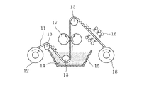
- FIG. 3 schematically shows an example of a configuration of a processing apparatus for making a resin porous body (hereinafter referred to as a band-shaped resin) conductive by making a resin molded body, which is a flat plate, long as a band, as an example of a practical manufacturing process.
- a processing apparatus for making a resin porous body hereinafter referred to as a band-shaped resin
- FIG. 3 schematically shows an example of a configuration of a processing apparatus for making a resin porous body (hereinafter referred to as a band-shaped resin) conductive by making a resin molded body, which is a flat plate, long as a band, as an example of a practical manufacturing process.
- this apparatus includes a supply bobbin 12 for supplying a belt-shaped resin 11, a tank 15 containing a conductive paint suspension 14, a pair of squeezing rolls 17 disposed above the tank 15, A plurality of hot air nozzles 16 provided opposite to the upper and lower surfaces of the belt-shaped resin 11 to be wound, and a winding bobbin 18 for winding the belt-shaped resin 11 after processing. Further, a deflector roll 13 for guiding the belt-shaped resin 11 is appropriately disposed.
- the strip-shaped resin 11 is unwound from the supply bobbin 12, guided by the deflector roll 13, and immersed in the suspension in the tank 15.
- the strip-shaped resin 11 immersed in the suspension 14 in the tank 15 changes its direction upward and travels between the squeeze rolls 17 above the liquid level of the suspension 14. At this time, the distance between the squeezing rolls 17 is smaller than the thickness of the strip-shaped resin 11, and the strip-shaped resin 11 is compressed. Therefore, the excess suspension impregnated in the belt-shaped resin 11 is squeezed out and returned to the tank 15.
- the strip-shaped resin 11 changes the traveling direction again.
- the suspension dispersion medium and the like are removed by hot air jetted by the hot air nozzle 16 composed of a plurality of nozzles, and the belt-like resin 11 is wound around the winding bobbin 18 after sufficiently drying.
- the temperature of the hot air ejected from the hot air nozzle 16 is preferably in the range of 40 ° C to 80 ° C.
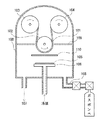
- FIG. 4 shows an overview of a direct current sputtering film forming apparatus.
- the DC sputtering deposition apparatus is in electrical and thermal contact with a chamber 100 that maintains a vacuum and a reduced pressure state, a cathode 106 and a target 105 that are cooled by a refrigerant, and a strip-shaped resin 101 on which a conductive layer is formed.
- the first drum functions as an anode, but is connected to the ground, and glow discharge plasma is generated by applying a DC voltage to the cathode.
- the chamber 100 is provided with an exhaust system 107 for evacuating the system, a gas piping system 108 for introducing an inert gas (for example, argon (Ar) gas) for generating plasma, and the like.
- an inert gas for example, argon (Ar) gas
- a protection plate 109 is installed so that plasma is not generated except in the portion of the first drum that faces the cathode.
- a shutter 110 is provided between the first drum and the cathode. The shutter 110 is closed at the start of glow discharge, and impurities on the target surface can be removed. During actual film formation, the shutter 110 is opened.
- the material is preferably a metal having high thermal conductivity such as copper.
- the temperature of the surface of the first drum is controlled so that thermal decomposition of the strip-shaped resin 101 is suppressed.
- the temperature of the surface of the first drum is also affected by the thickness of the strip-shaped resin 101 and the thickness of the metal film to be formed. That is, if the strip-shaped resin 101 is thick, the thermal conductivity is deteriorated, so the surface temperature of the first drum needs to be further lowered. If a thick metal film is to be formed, the film formation time becomes longer, and the time for the strip-shaped resin 101 to be exposed to plasma becomes longer. Therefore, the temperature of the first drum needs to be lowered.
- the inside of the chamber 100 is once evacuated to 10 ⁇ 4 Pa. Thereafter, Ar gas is introduced into the chamber 100 until the pressure reaches 1 Pa to 10 2 Pa. After the inside of the chamber reaches a certain pressure, a predetermined DC voltage is applied between the anode and the cathode to generate plasma by glow discharge. This DC voltage is usually adjusted to about several hundred volts to about 5 kV. The generated current value is about 10 ⁇ 1 to 10 2 A / m 2 , and the film formation rate can be increased by setting this current value high.
- a metal film is formed on the belt-shaped resin 101 by gasifying the raw material from the target by the generated plasma.
- the film thickness of the metal film at the surface position of the strip-shaped resin 101 having a flat plate shape is 10 ⁇ m, it takes about 1 to 3 hours to form the metal film with the cathode of the first drum. It moves on the opposing surface. Thereby, a metal film is formed on one surface of the belt-like resin 101.
- the belt-shaped resin 101 After the formation of the metal film on one surface of the belt-shaped resin 101 is completed, the belt-shaped resin 101 is rewinded, the surface on which the film is not formed is turned outside, and the metal film is formed again in the same manner as described above. Thus, a band-shaped metal structure in which a metal film is formed on the band-shaped resin molded body is created.
- the strip-shaped metal structure is heated to thermally decompose and remove the resin molded body.
- the heating condition may be air or an inert atmosphere such as nitrogen gas.
- the heating temperature may be equal to or higher than the thermal decomposition temperature of polyurethane or melamine resin as the material of the resin molded body, but is usually 400 ° C. or higher and 650 ° C. or lower. When the temperature exceeds 650 ° C., the oxidation of the metal film is promoted.
- Example 1 A porous metal body made of aluminum is prepared.
- the film forming apparatus shown in FIG. 4 is used.
- the distance between the target and the first drum is set to 10 cm.
- An aluminum plate is used for the target.
- polyurethane having a foamed thickness of 1 mm, a width of 10 cm, and an average pore diameter of 300 ⁇ m is used.
- Carbon is applied to the resin molded body. Carbon particles having an average particle size of 0.1 ⁇ m to 0.3 ⁇ m are used.
- the thickness of the carbon coating layer is about 1 ⁇ m.
- the surface temperature of the first drum is cooled to ⁇ 10 ° C. by circulating the fluorinated inert liquid cooled by the cooling device.
- the belt-shaped resin is moved at a constant speed while being in close contact with the first drum by roll-to-roll.
- Ar gas is controlled in the chamber so that the pressure becomes 1 Pa.
- a glow discharge plasma is generated by applying a DC voltage of 1 kV between the anode and the cathode.
- the current value at this time is about 2A.
- the surface temperature of the belt-like resin is 75 ° C. as measured by a radiation thermometer.
- the feeding speed of the belt-shaped resin was set to a speed for moving the half surface of the first drum (diameter: 50 cm) facing the cathode in 2 hours.
- the belt-shaped resin is re-rolled, the surface on which the film is not formed is turned outside, and the metal film is formed again in the same manner as described above.
- the obtained metal structure is heated at 500 ° C. for 15 minutes in the air to remove the resin molded body.
- the thickness of the obtained porous aluminum body is 1 mm, the thickness of the aluminum film at the surface position is 15 ⁇ m, and the thickness of the central aluminum film in the thickness direction is 12 ⁇ m.
- the compression test of the obtained aluminum porous body is performed. The aluminum porous body is cut into a 10 cm square and compressed to half the thickness in the thickness direction. No cracks occur in the aluminum skeleton constituting the aluminum porous body. Further, the difference in the average pore diameter after compression between the surface layer of the porous aluminum body and the central portion in the thickness direction is suppressed to about 90%.
- a nickel porous body is produced in the same manner as in Example 1.
- the thickness of the nickel film at the surface position of the obtained nickel porous body is 15 ⁇ m, and the thickness of the nickel film at the center in the thickness direction is 12 ⁇ m.
- the compression test of the obtained nickel porous body is performed. A nickel porous body is cut into a 10 cm square and compressed to half the thickness in the thickness direction. The nickel skeleton constituting the nickel porous body is not cracked. Further, the difference in the average pore diameter after compression between the surface layer of the nickel porous body and the central portion in the thickness direction is suppressed to about 90%.
- a porous aluminum body is produced in the same manner as in Example 1 except that the first drum is not cooled.
- the thickness of the obtained aluminum porous body is thinner than the initial thickness of the resin molded body, and the pore size distribution also varies widely.
- the compression test of the obtained aluminum porous body is performed.
- the aluminum porous body is cut into a 10 cm square and compressed to half the thickness in the thickness direction. It can be seen that the aluminum skeleton constituting the aluminum porous body is cracked and cut, resulting in embrittlement.
- porous metal body produced according to the present invention can be suitably used as a porous metal body in applications such as various filters and battery electrodes.
Landscapes
- Chemical & Material Sciences (AREA)
- Engineering & Computer Science (AREA)
- Mechanical Engineering (AREA)
- Materials Engineering (AREA)
- Metallurgy (AREA)
- Organic Chemistry (AREA)
- Chemical Kinetics & Catalysis (AREA)
- Manufacturing & Machinery (AREA)
- Cell Electrode Carriers And Collectors (AREA)
- Physical Vapour Deposition (AREA)
Applications Claiming Priority (2)
| Application Number | Priority Date | Filing Date | Title |
|---|---|---|---|
| JP2012146252A JP2015165036A (ja) | 2012-06-29 | 2012-06-29 | 金属多孔体の製造方法および金属多孔体 |
| JP2012-146252 | 2012-06-29 |
Publications (1)
| Publication Number | Publication Date |
|---|---|
| WO2014002777A1 true WO2014002777A1 (fr) | 2014-01-03 |
Family
ID=49782939
Family Applications (1)
| Application Number | Title | Priority Date | Filing Date |
|---|---|---|---|
| PCT/JP2013/066293 Ceased WO2014002777A1 (fr) | 2012-06-29 | 2013-06-13 | Procédé de production d'un corps métallique poreux, et corps métallique poreux |
Country Status (2)
| Country | Link |
|---|---|
| JP (1) | JP2015165036A (fr) |
| WO (1) | WO2014002777A1 (fr) |
Cited By (2)
| Publication number | Priority date | Publication date | Assignee | Title |
|---|---|---|---|---|
| CN105039771A (zh) * | 2015-02-25 | 2015-11-11 | 上海交通大学 | 一种三维连通多孔镁基材料的制备方法及其用途 |
| EP3709322A4 (fr) * | 2018-03-16 | 2021-09-29 | Jiangsu Zhongtian Technology Co., Ltd. | Corps macroscopique en aluminium poreux et système de fabrication et procédé associé |
Families Citing this family (1)
| Publication number | Priority date | Publication date | Assignee | Title |
|---|---|---|---|---|
| WO2020049851A1 (fr) * | 2018-09-07 | 2020-03-12 | 富山住友電工株式会社 | Corps poreux métallique, pile à combustible et procédé de fabrication de corps poreux métallique |
Citations (1)
| Publication number | Priority date | Publication date | Assignee | Title |
|---|---|---|---|---|
| JPH0610077A (ja) * | 1992-01-13 | 1994-01-18 | C Uyemura & Co Ltd | アルミニウム多孔体の製造方法 |
-
2012
- 2012-06-29 JP JP2012146252A patent/JP2015165036A/ja active Pending
-
2013
- 2013-06-13 WO PCT/JP2013/066293 patent/WO2014002777A1/fr not_active Ceased
Patent Citations (1)
| Publication number | Priority date | Publication date | Assignee | Title |
|---|---|---|---|---|
| JPH0610077A (ja) * | 1992-01-13 | 1994-01-18 | C Uyemura & Co Ltd | アルミニウム多孔体の製造方法 |
Cited By (3)
| Publication number | Priority date | Publication date | Assignee | Title |
|---|---|---|---|---|
| CN105039771A (zh) * | 2015-02-25 | 2015-11-11 | 上海交通大学 | 一种三维连通多孔镁基材料的制备方法及其用途 |
| EP3709322A4 (fr) * | 2018-03-16 | 2021-09-29 | Jiangsu Zhongtian Technology Co., Ltd. | Corps macroscopique en aluminium poreux et système de fabrication et procédé associé |
| US11268187B2 (en) | 2018-03-16 | 2022-03-08 | Jiangsu Zhongtian Technology Co., Ltd. | Porous aluminum macroscopic body and fabrication system and method therefor |
Also Published As
| Publication number | Publication date |
|---|---|
| JP2015165036A (ja) | 2015-09-17 |
Similar Documents
| Publication | Publication Date | Title |
|---|---|---|
| CN102666887B (zh) | 用于制造铝结构体的方法和铝结构体 | |
| US20120295169A1 (en) | Air battery and electrode | |
| JP2012007233A (ja) | アルミニウム構造体の製造方法およびアルミニウム構造体 | |
| KR102032265B1 (ko) | 리튬이차전지 음극 집전체용 다공성 구리의 제조 방법 및 이에 따라 제조된 다공성 구리 및 리튬이차전지 음극 집전체 | |
| WO2012096220A1 (fr) | Procédé de production d'une structure d'aluminium, et structure d'aluminium | |
| JP2012186160A (ja) | 電池 | |
| CN102666934A (zh) | 铝结构体的制造方法和铝结构体 | |
| JPWO2011043026A1 (ja) | リチウムイオン二次電池用負極およびリチウムイオン二次電池 | |
| CN103582721B (zh) | 铝结构体的制造方法和铝结构体 | |
| WO2012165213A1 (fr) | Corps métallique poreux, matière d'électrode l'utilisant et cellule | |
| JP2012255185A (ja) | アルミニウム多孔体の製造方法及び製造装置 | |
| WO2014002777A1 (fr) | Procédé de production d'un corps métallique poreux, et corps métallique poreux | |
| WO2012036065A1 (fr) | Procédé de production d'une structure en aluminium, et structure en aluminium associée | |
| JP5704026B2 (ja) | アルミニウム構造体の製造方法 | |
| JP5692233B2 (ja) | アルミニウム構造体の製造方法およびアルミニウム構造体 | |
| US9863045B2 (en) | Electrochemical process for the preparation of lead foam | |
| KR102096448B1 (ko) | 그래핀 코팅 동박 제조방법 및 제조장치 | |
| JP2013194308A (ja) | 金属多孔体及びそれを用いた電極材料、電池 | |
| JP4811681B2 (ja) | 電極集電体の製造方法及び製造装置ならびに該集電体を備えた電池 | |
| JP6331808B2 (ja) | アルミニウム多孔体の製造方法 | |
| KR102791327B1 (ko) | 리튬메탈전지의 음극재 제조방법 | |
| KR101745552B1 (ko) | 나노포러스구조를 구비하는 연료전지 촉매전극 제조방법 및 이에 의한 연료전지 촉매전극 | |
| KR102924605B1 (ko) | 대면적 티타늄 다공성 수송층의 제조방법 | |
| JP2012255187A (ja) | アルミニウム多孔体の製造方法及び製造装置 | |
| JP2015083716A (ja) | アルミニウム構造体を含む電極材料、それを用いた電池および電気二重層コンデンサ、ならびにアルミニウム構造体を用いた濾過フィルタおよび触媒担体 |
Legal Events
| Date | Code | Title | Description |
|---|---|---|---|
| 121 | Ep: the epo has been informed by wipo that ep was designated in this application |
Ref document number: 13810765 Country of ref document: EP Kind code of ref document: A1 |
|
| NENP | Non-entry into the national phase |
Ref country code: DE |
|
| 122 | Ep: pct application non-entry in european phase |
Ref document number: 13810765 Country of ref document: EP Kind code of ref document: A1 |
|
| NENP | Non-entry into the national phase |
Ref country code: JP |