WO2014003059A1 - Mécanisme d'ouverture/fermeture à registre et dispositif de cuisson le comprenant - Google Patents
Mécanisme d'ouverture/fermeture à registre et dispositif de cuisson le comprenant Download PDFInfo
- Publication number
- WO2014003059A1 WO2014003059A1 PCT/JP2013/067520 JP2013067520W WO2014003059A1 WO 2014003059 A1 WO2014003059 A1 WO 2014003059A1 JP 2013067520 W JP2013067520 W JP 2013067520W WO 2014003059 A1 WO2014003059 A1 WO 2014003059A1
- Authority
- WO
- WIPO (PCT)
- Prior art keywords
- damper
- closing mechanism
- slider
- operating lever
- damper opening
- Prior art date
- Legal status (The legal status is an assumption and is not a legal conclusion. Google has not performed a legal analysis and makes no representation as to the accuracy of the status listed.)
- Ceased
Links
Images




Classifications
-
- F—MECHANICAL ENGINEERING; LIGHTING; HEATING; WEAPONS; BLASTING
- F23—COMBUSTION APPARATUS; COMBUSTION PROCESSES
- F23L—SUPPLYING AIR OR NON-COMBUSTIBLE LIQUIDS OR GASES TO COMBUSTION APPARATUS IN GENERAL ; VALVES OR DAMPERS SPECIALLY ADAPTED FOR CONTROLLING AIR SUPPLY OR DRAUGHT IN COMBUSTION APPARATUS; INDUCING DRAUGHT IN COMBUSTION APPARATUS; TOPS FOR CHIMNEYS OR VENTILATING SHAFTS; TERMINALS FOR FLUES
- F23L13/00—Construction of valves or dampers for controlling air supply or draught
- F23L13/02—Construction of valves or dampers for controlling air supply or draught pivoted about a single axis but having not other movement
-
- F—MECHANICAL ENGINEERING; LIGHTING; HEATING; WEAPONS; BLASTING
- F16—ENGINEERING ELEMENTS AND UNITS; GENERAL MEASURES FOR PRODUCING AND MAINTAINING EFFECTIVE FUNCTIONING OF MACHINES OR INSTALLATIONS; THERMAL INSULATION IN GENERAL
- F16K—VALVES; TAPS; COCKS; ACTUATING-FLOATS; DEVICES FOR VENTING OR AERATING
- F16K1/00—Lift valves or globe valves, i.e. cut-off apparatus with closure members having at least a component of their opening and closing motion perpendicular to the closing faces
- F16K1/16—Lift valves or globe valves, i.e. cut-off apparatus with closure members having at least a component of their opening and closing motion perpendicular to the closing faces with pivoted closure-members
-
- F—MECHANICAL ENGINEERING; LIGHTING; HEATING; WEAPONS; BLASTING
- F16—ENGINEERING ELEMENTS AND UNITS; GENERAL MEASURES FOR PRODUCING AND MAINTAINING EFFECTIVE FUNCTIONING OF MACHINES OR INSTALLATIONS; THERMAL INSULATION IN GENERAL
- F16K—VALVES; TAPS; COCKS; ACTUATING-FLOATS; DEVICES FOR VENTING OR AERATING
- F16K11/00—Multiple-way valves, e.g. mixing valves; Pipe fittings incorporating such valves
- F16K11/02—Multiple-way valves, e.g. mixing valves; Pipe fittings incorporating such valves with all movable sealing faces moving as one unit
- F16K11/04—Multiple-way valves, e.g. mixing valves; Pipe fittings incorporating such valves with all movable sealing faces moving as one unit comprising only lift valves
- F16K11/052—Multiple-way valves, e.g. mixing valves; Pipe fittings incorporating such valves with all movable sealing faces moving as one unit comprising only lift valves with pivoted closure members, e.g. butterfly valves
-
- F—MECHANICAL ENGINEERING; LIGHTING; HEATING; WEAPONS; BLASTING
- F16—ENGINEERING ELEMENTS AND UNITS; GENERAL MEASURES FOR PRODUCING AND MAINTAINING EFFECTIVE FUNCTIONING OF MACHINES OR INSTALLATIONS; THERMAL INSULATION IN GENERAL
- F16K—VALVES; TAPS; COCKS; ACTUATING-FLOATS; DEVICES FOR VENTING OR AERATING
- F16K31/00—Actuating devices; Operating means; Releasing devices
- F16K31/44—Mechanical actuating means
-
- F—MECHANICAL ENGINEERING; LIGHTING; HEATING; WEAPONS; BLASTING
- F24—HEATING; RANGES; VENTILATING
- F24C—DOMESTIC STOVES OR RANGES ; DETAILS OF DOMESTIC STOVES OR RANGES, OF GENERAL APPLICATION
- F24C15/00—Details
- F24C15/32—Arrangements of ducts for hot gases, e.g. in or around baking ovens
- F24C15/322—Arrangements of ducts for hot gases, e.g. in or around baking ovens with forced circulation
- F24C15/325—Arrangements of ducts for hot gases, e.g. in or around baking ovens with forced circulation electrically-heated
-
- H—ELECTRICITY
- H05—ELECTRIC TECHNIQUES NOT OTHERWISE PROVIDED FOR
- H05B—ELECTRIC HEATING; ELECTRIC LIGHT SOURCES NOT OTHERWISE PROVIDED FOR; CIRCUIT ARRANGEMENTS FOR ELECTRIC LIGHT SOURCES, IN GENERAL
- H05B6/00—Heating by electric, magnetic or electromagnetic fields
- H05B6/64—Heating using microwaves
- H05B6/6447—Method of operation or details of the microwave heating apparatus related to the use of detectors or sensors
- H05B6/645—Method of operation or details of the microwave heating apparatus related to the use of detectors or sensors using temperature sensors
-
- H—ELECTRICITY
- H05—ELECTRIC TECHNIQUES NOT OTHERWISE PROVIDED FOR
- H05B—ELECTRIC HEATING; ELECTRIC LIGHT SOURCES NOT OTHERWISE PROVIDED FOR; CIRCUIT ARRANGEMENTS FOR ELECTRIC LIGHT SOURCES, IN GENERAL
- H05B6/00—Heating by electric, magnetic or electromagnetic fields
- H05B6/64—Heating using microwaves
- H05B6/647—Aspects related to microwave heating combined with other heating techniques
- H05B6/6473—Aspects related to microwave heating combined with other heating techniques combined with convection heating
- H05B6/6479—Aspects related to microwave heating combined with other heating techniques combined with convection heating using steam
-
- H—ELECTRICITY
- H05—ELECTRIC TECHNIQUES NOT OTHERWISE PROVIDED FOR
- H05B—ELECTRIC HEATING; ELECTRIC LIGHT SOURCES NOT OTHERWISE PROVIDED FOR; CIRCUIT ARRANGEMENTS FOR ELECTRIC LIGHT SOURCES, IN GENERAL
- H05B6/00—Heating by electric, magnetic or electromagnetic fields
- H05B6/64—Heating using microwaves
- H05B6/72—Radiators or antennas
- H05B6/725—Rotatable antennas
Definitions
- the present invention relates to a damper opening / closing mechanism suitable for opening / closing a damper provided in a hot air flow path under a high temperature environment, and a cooking device provided with the same.
- the heating cooker since the hot air circulates in the entire heating chamber in either one-step cooking or two-step cooking, the heating time is hardly changed even in the case of one-step cooking with a small amount of food. There is a drawback that the heating time for one-step cooking cannot be shortened.
- the heat medium is circulated in order to efficiently circulate the heat medium during the first-stage cooking and to shorten the heating time during the first-stage cooking rather than the two-stage cooking. It is conceivable to provide a damper in the path and to open and close the upper air outlet that blows out to the upper area of the heating chamber.
- the circulation path becomes a high temperature of 100 ° C. or higher because a high-temperature heat medium flows inside. Accordingly, the damper itself provided in the circulation path also becomes high temperature. Therefore, it is necessary to install a motor for opening and closing the damper at a position away from the damper, and it is difficult to make the opening and closing mechanism compact, and the mounting position of the opening and closing mechanism varies among individual cookers. Therefore, there is a problem that it is difficult to obtain a reliable opening / closing operation.
- packing is necessary to reduce the collision noise with the circulation path and the wall surface of the heating chamber generated when the damper is opened and closed, and to seal the upper outlet with the damper.
- packing such as rubber cannot be used.
- an object of the present invention is to provide a damper opening / closing mechanism that can perform reliable opening / closing operation of the damper even when the mounting position varies among individual devices and can reduce collision noise. And it is providing the cooking device provided with the same.
- the damper opening / closing mechanism of the present invention is: A damper that swings around an axis to open and close the flow path; An operating lever that swings to swing the damper about the axis; A reciprocating part that reciprocates; An elastic member that is attached to the reciprocating portion and is positioned on both sides of the forward and double directions of the swinging direction of the operating lever and elastically biasing the operating lever as the reciprocating portion reciprocates It is characterized by having.
- the elastic member that elastically biases the operating lever as the reciprocating unit reciprocates on both sides of the reciprocating unit in the forward and double directions of the swinging direction of the operating lever.
- the damper completely closes and opens the flow path, the elastic force of the elastic member can be applied to the operating lever. Therefore, even when a positional deviation occurs between the center of the reciprocating range of the reciprocating part and the center of the swinging range of the damper during assembly, the operation deviation between the reciprocating part and the damper due to the positional deviation is caused. Can be absorbed by deformation of the elastic member.
- the damper can completely close and open the flow path even when there is a deviation between the reciprocating range of the reciprocating part and the swinging range of the damper during assembly. Therefore, even when the mounting position of the opening / closing mechanism of the damper varies between devices, the damper can be reliably opened / closed.
- the operating lever is elastically biased by the elastic member. Therefore, the impact when the damper completely closes and opens the flow path can be mitigated by the elastic force of the elastic member, and the impact sound between the damper and the flow path can be reduced.
- the operating lever is elastically biased by the elastic member. Therefore, even if the damper is in contact with the flow path in the vicinity of the dead center of the reciprocating motion or the reciprocating motion in the power unit of the reciprocating portion, the reciprocating portion is moved in the forward direction or multiple directions due to deformation of the elastic member. It becomes possible to continue moving in the direction. Therefore, when the damper completely closes and opens the flow path, it is possible to prevent the power unit from being overloaded and causing a problem.
- the reciprocating part is a slider that is guided by a guide part and reciprocates in a straight line direction.
- the reciprocating part is configured by a slider, the reciprocating part can be configured to be thin and small, and can be installed even in a narrow space.
- the elastic member is a torsion spring.
- the elastic member is constituted by a torsion spring, the reciprocating part can be made thin and small.
- the main body of the reciprocating portion has a hole through which the operating lever is inserted with an interval in the swinging direction of the operating lever, and the operating lever that is inserted into the hole when the operating lever is inserted into the hole.
- it has a stopper pin that positions the two torsion springs at intervals.
- the two torsion springs that elastically bias the operating lever as the reciprocating portion reciprocates are positioned by the stopper pin. Therefore, the timing at which the torsion spring acts on the operating lever can be set to an optimal timing for the damper to close and open the flow path.
- the torsion spring biases the main body of the reciprocating portion so as not to be detached from the stopper pin in the axial direction of the stopper pin.
- the torsion spring is not separated from the stopper pin, the torsion spring is detached from the stopper pin even if the reciprocating part vibrates during the reciprocation.
- the operation of the stopper pin and the torsion spring can be performed reliably.
- a cam mechanism is provided for converting the rotational movement of the motor shaft into the reciprocating motion of the slider in the linear direction.
- the slider can be reciprocated in the linear direction by the motor.
- the heating cooker of this invention is A heating chamber for storing and heating an object to be heated; A heat medium generating section for generating a heat medium to be supplied to the heating chamber; A flow path through which the heat medium flows;
- the damper opening and closing mechanism of the present invention The damper of the damper opening / closing mechanism opens and closes the flow path.
- the damper includes a damper opening / closing mechanism that allows the damper to completely close and open the flow path even if a deviation occurs between the reciprocating range of the reciprocating portion and the swinging range of the damper. Yes. Therefore, since the flow path through which the heat medium flows is opened and closed, the damper itself also becomes high temperature. Therefore, when the damper opening and closing mechanism is installed at a position away from the damper, the mounting position of the damper opening and closing mechanism is individually set. Even if a variation occurs between the heating cookers and a deviation occurs between the reciprocating range of the reciprocating unit and the swinging range of the damper due to variations in the mounting position, a reliable opening / closing operation of the damper is obtained. Can do.
- damper opening / closing mechanism elastically urges the operating lever by the elastic member, it is possible to reduce a collision sound generated when the damper is opened / closed without providing a packing.
- the damper opening / closing mechanism of the present invention elastically urges the operating lever on both sides of the reciprocating portion in the swinging direction of the operating lever as the reciprocating portion reciprocates. Since the elastic member is provided, the elastic force of the elastic member can be applied to the operating lever when the damper closes and opens the flow path. Therefore, even when a positional deviation occurs between the center of the reciprocating range of the reciprocating part and the center of the swinging range of the damper during assembly, the operation deviation between the reciprocating part and the damper is caused by the positional deviation. Can be absorbed by deformation of the elastic member.
- the operating lever is elastically urged by the elastic member, an impact when the damper closes and opens the flow path can be reduced by the elastic force of the elastic member, and the damper It is possible to reduce the collision noise between the above and the flow path.
- the damper since the operating lever is elastically urged by the elastic member, the damper is in contact with the flow path in the vicinity of the rotating operation or the dead center of the reciprocating operation in the power unit of the reciprocating unit.
- the reciprocating part can continue to move in the forward direction or in multiple directions by deformation of the elastic member. Therefore, when the damper completely closes and opens the flow path, it is possible to prevent the power unit from being overloaded and causing a problem.
- the damper can be silenced without using a silencing or sealing packing. A reliable opening and closing operation can be performed.
- the cooking device of the present invention provides a damper opening and closing that allows the damper to completely close and open the flow path even if there is a deviation between the reciprocating range of the reciprocating portion and the swinging range of the damper. It has a mechanism. Therefore, since the damper itself that opens and closes the flow path through which the heat medium flows becomes high temperature, when the opening and closing mechanism of the damper is installed at a position away from the damper, the mounting position of the opening and closing mechanism is an individual cooking device. Even if variations occur between them, a reliable opening / closing operation of the damper can be obtained, and a collision sound when the damper is opened / closed can be reduced without providing a packing.
- FIG. 4 is a perspective view of the heating cooker with the casing removed, as viewed from the second duct portion side.
- FIG. 5 (a) is a plan view of the damper in FIG. 4, and
- FIG. 5 (b) is a side view. It is an enlarged view of a slider when a damper is opened. It is an enlarged view of a slider when a damper is closed. Fig.
- FIG. 8 (a) is a view of the slider and slider mounting plate when the damper is closed from the back side
- Fig. 8 (c) is a view when the damper is open
- Fig. 8 (b) is an intermediate state of the damper.
- FIG. FIG. 9A is a cross-sectional view showing a closed state of the damper
- FIG. 9B is a cross-sectional view showing an open state.
- FIG. 10 (a) is a diagram showing the state of the slider and torsion spring when the slider slides upward
- FIG. 10 (b) is a diagram when the slider slides further upward
- FIG. 10 (c) is a diagram when the slider is further slid upward
- FIG. 10 (d) is a diagram when the slider is positioned at the uppermost position. It is a side view of a torsion spring.
- the damper opening / closing mechanism of the present invention is applied to a heating cooker as an example.
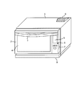
- FIG. 1 is a front perspective view of a heating cooker to which the damper opening / closing mechanism of the present embodiment is applied.
- this cooking device is provided with a door 2 that rotates about a lower end side on the front side of a rectangular parallelepiped casing 1.
- a handle 3 is attached to the upper part of the door 2, and a heat-resistant glass 4 is attached to the approximate center.
- An operation panel 5 is provided on the right side of the door 2 in the drawing.
- the operation panel 5 includes a color liquid crystal display unit 6 and a button group 7.
- an exhaust duct 8 is provided on the upper right side of the casing 1 on the right rear side.
- a dew receptacle 9 is detachably attached below the door 2 of the casing 1.
- the color liquid crystal display unit 6 is configured by overlapping a touch panel on a color liquid crystal panel, and can touch the touch panel to select an image such as a menu displayed on the color liquid crystal panel.
- the color liquid crystal panel not only the color liquid crystal panel but also other display devices such as an organic EL may be used, or a monochrome display may be used.
- FIG. 2 is a schematic diagram of a longitudinal section viewed from the door 2 side (front side) of the cooking device shown in FIG. As shown in FIG. 2, this cooking device heats water supplied from the water tank 11 with a steam generator 12 to generate saturated steam. Saturated steam generated by the steam generator 12 passes through a steam supply passage (not shown) to the heating chamber 13 side of the steam inlet 15 in the circulation unit 14 attached to the right side of the heating chamber 13 in the drawing. It is supplied and ejected from the steam supply pipe 16 connected to the steam supply passage.
- the steam supply pipe 16 is attached in the vicinity of the steam inlet 15 of the circulation unit 14 so as to be parallel to the right side surface of the heating chamber 13.
- a circulation fan 17 that is rotationally driven by a circulation fan motor 18 is disposed in the circulation unit 14 so as to face the vapor suction port 15.
- a steam duct 19 bent in an L shape is provided so as to cover the top surface of the heating chamber 13 and the left side surface in the figure.
- the steam duct 19 is fixed to the first duct portion 20 fixed to the top surface of the heating chamber 13, the bent portion 21 bent downward from the left side of the first duct portion 20, and the left side surface of the heating chamber 13.
- a second duct portion 22 connected to the first duct portion 20 via the bent portion 21.
- a superheated steam generation heater 23 is accommodated in the first duct portion 20 of the steam duct 19.
- the superheated steam generating heater 23 and the steam generating device 12 constitute the heat medium generating unit.
- the right side of the first duct portion 20 in the steam duct 19 in the drawing communicates with a steam supply port 26 provided in the upper part of the circulation unit 14.
- the top plate 27 of the heating chamber 13 is provided with a plurality of first steam outlets 28, and the first duct portion 20 of the steam duct 19 communicates with the inside of the heating chamber 13 via the first steam outlet 28.
- the second duct portion 22 in the steam duct 19 communicates with the inside of the heating chamber 13 through a plurality of second steam outlets 29a, 29b, 29c, 29d provided on the left side surface of the heating chamber 13.
- the gap between the heating chamber 13 and the steam duct 19 is sealed with a heat resistant resin or the like.
- the heating chamber 13 and the steam duct 19 are covered with a heat insulating material except for the front opening of the heating chamber 13.
- locking portions 33a, 33b, and 33c that lock both ends of the tray 30 are provided in three stages in the vertical direction on the right side and the left side in the heating chamber 13.
- a steam circulation path as an example of the flow path is formed by the circulation unit 14, the first duct portion 20, the heating chamber 13, and the connection member that connects them. Then, saturated steam generated by the steam generator 12 is supplied to a boundary portion of the circulation unit 14 with the heating chamber 13 in this circulation path.
- a magnetron (not shown) is disposed below the heating chamber 13.
- the microwave generated by the magnetron is guided to the lower center of the heating chamber 13 by a waveguide (not shown), and is stirred upward by the rotating antenna 35 driven by the motor 34 toward the upper side in the heating chamber 13.
- the object to be heated 31 is heated by being emitted.
- the electrical component 36 has a control device including a drive circuit that drives each part of the cooking device, a control circuit that controls the drive circuit, and the like.
- the second steam jetting port has a fulcrum on the wall surface of the heating chamber 13 above the uppermost locking portion 33a in the second duct portion 22 and below the uppermost second steam jetting port 29a.
- a damper 37 for opening and closing 29a is provided.
- the length of the inner side of the 2nd duct part 22 and the damper 37 in the front-back direction of this heating cooker is substantially the same.
- the both ends of the tray 30 are locked to the locking portion 33a, whereby the inside of the heating chamber 13 is divided into an upper region above the tray 30 and a lower region below. Therefore, after the tray 30 is locked to the uppermost locking portion 33a, the damper 37 opens the second steam outlet 29a, so that the steam duct 19 communicates with only the upper region of the heating chamber 13 only. It becomes.
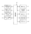
- FIG. 3 shows a control block diagram of the cooking device.
- This cooking device has the control device 41 including a microcomputer and an input / output circuit in an electrical component section 36 (shown in FIG. 2).
- the control device 41 includes a superheated steam generation heater 23, a circulation fan motor 18, a cooling fan motor 42, a damper switching motor 43, an operation panel 5, an internal temperature sensor 44, a feed water pump 45, and a steam generation device 12.
- the magnetron 46 is connected. Then, based on the signal from the operation panel 5 and the detection signal from the internal temperature sensor 44, the control device 41 controls the superheated steam generation heater 23, the circulation fan motor 18, the cooling fan motor 42, and the damper switching motor 43. , The operation panel 5, the feed water pump 45, the steam generator 12, and the magnetron 46 are controlled.
- the steam generator 12 shown in FIG. 2 when cooking with superheated steam, the steam generator 12 shown in FIG. 2 is driven, the superheated steam generator heater 23 is turned on, and the circulation fan 17 is driven to rotate. Then, the saturated steam supplied from the steam generator 12 to the upstream side in the vicinity of the steam suction port 15 of the circulation unit 14 passes through the steam suction port 15 into the circulation unit 14 which is in a negative pressure due to the rotation of the circulation fan 17. And sucked. In this way, the saturated water vapor combined with the circulating air flow circulating through the circulation path of the steam formed by the circulation unit 14, the first duct portion 20, the heating chamber 13, and the connecting member connecting them is first fed from the steam supply port 26. The air is blown into the duct portion 20.
- the superheated steam supplied in the said heating chamber 13 heats the to-be-heated object 31 mounted on the tray 30 of two steps of upper and lower sides, Then, the vapor
- the cooling fan motor 42 is driven when air for cooling the electrical component 36 is taken in.
- the internal temperature sensor 44 detects the temperature in the heating chamber 13 when cooking is performed.
- the water supply pump 45 is driven when supplying water from the water tank 11 to the steam generator 12.
- the magnetron 46 is driven when the object to be heated 31 is heated by microwaves.
- damper 37 and a damper opening / closing mechanism that opens and closes the damper 37 driven by the damper switching motor 43 will be described in detail.
- FIG. 4 is a perspective view of the cooking device with the casing 1 removed as viewed from the second duct portion 22 side.
- the damper 37 is disposed so as to extend in the horizontal direction in the second duct portion 22, and the end portion on the right side of the damper 37 in the drawing is a rotating shaft provided on the wall surface side of the heating chamber 13. (Not shown) is rotatably supported by the shaft.
- the end on the left side in the drawing is pivotally supported by a rotating shaft 47.
- the rotating shaft 47 extends toward the left in the drawing through the back side of the side panel 48 that covers the side surfaces of the heating chamber 13 and the second duct portion 22, and the tip thereof is substantially perpendicular to the outer direction.
- the actuating lever 49 is formed by being bent in a circle. The operating lever 49 protrudes outward from a hole (not shown) provided in the side panel 48.
- the operating lever 49 is inserted through a hole 50a of a slider 50 that is slidably attached to the side panel 48 as will be described in detail later.
- the operation lever 49 swings around the rotation shaft 47, and the rotation shaft 47 rotates, whereby the damper 37 swings and the second steam jets.
- the outlet 29a is opened and closed.
- the slider 50 is attached to a slider attachment plate 52 attached to the side panel 48 via a motor attachment plate 51 so as to be slidable up and down.
- a cam mechanism for converting a rotational motion of a pin (not shown) rotated by a damper switching motor 43 attached to the motor mounting plate 51 into a vertical motion is provided below the slider 50, as will be described in detail later. Is provided.
- the slider 50 is driven by the damper switching motor 43 and slides up and down.
- the operating lever 49 swings, and the damper 37 opens and closes the second steam outlet 29a.
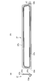
- FIG. 5 shows a plan view (FIG. 5 (b)) and a side view (FIG. 5 (a)) of the damper 37.
- the left and right lengths of the damper 37 in FIG. 5B are substantially the same as the left and right lengths of the second duct portion 22 in FIG. 4, and the periphery of the damper 37 is the second length.
- the second duct portion 22 can be closed by being in close contact with the inner surface of the duct portion 22.
- a rotating shaft (not shown) provided on the wall surface side of the heating chamber 13 is provided at the end of the damper 37 on the left side in FIG.
- a bearing 53a is provided.
- the surface of the damper 37 on the side of the heating chamber 13 is formed with an annular projecting portion 37a that has a shape along the periphery of the second steam outlet 29a and projects toward the heating chamber 13 side. .
- the damper 37 closes the second steam ejection port 29a, the protrusion 37a is in close contact with the periphery of the second steam ejection port 29a and seals the second steam ejection port 29a.
- the peripheral edge including the tip edge 37b is formed.
- the second duct part 22 is closed in close contact with the inner surface of the second duct part 22.
- the annular protrusion 37a is brought into close contact with the periphery of the second steam outlet 29a to close the second steam outlet 29a.
- one end of the rotary shaft 47 is attached to the bearing 53b at the right end in FIG. 5B of the damper 37, but the rotary shaft is the same as in the case of the bearing 53a.
- the operation lever for swinging the damper 37 may be provided on a rotation shaft different from the rotation shaft 47. The point is that the damper 37 may be configured to swing around the rotation shaft 47.
- FIG. 6 and 7 are enlarged views of the slider 50 and the slider mounting plate 52 shown in FIG.
- FIG. 6 shows a case where the damper 37 opens the second steam outlet 29a.
- FIG. 7 shows a case where the damper 37 closes the second steam ejection port 29a.
- the operation lever 49 rotates downward about the rotation shaft 47.
- the damper 37 opens the second steam outlet 29 a and closes the second duct portion 22 by rotating the operating lever 49 downward.
- FIG. 7 when the slider 50 slides upward with respect to the side panel 48 and the slider mounting plate 52, the operation lever 49 rotates upward about the rotation shaft 47.
- the rotating shaft 47 rotates upward, so that the damper 37 closes the second steam jet outlet 29 a and opens the second duct portion 22.
- FIG. 8 is a view of the slider 50 and the slider mounting plate 52 as viewed from the back side of FIGS. 6 and 7 in order to explain the operation of the slider 50 and the slider mounting plate 52.
- FIG. 8A shows a case where the damper 37 completely closes the second steam outlet 29a.
- FIG.8 (c) shows the case where the damper 37 has open
- FIG. 8 (b) shows an intermediate case between FIG. 8 (a) and FIG. 8 (c).
- a linear slot 56 is formed in the center of the slider 50 in the vertical direction.
- the width of the long hole 56 is set to be slightly larger than the diameter of the threaded portion 57a (see FIGS. 6 and 7) of the two screws 57 and 57 to be inserted and smaller than the diameter of the head portion 57b. Then, by attaching the slider 50 to the slider mounting plate 52 with two screws 57 and 57 with a gap, the slider 50 is attached to the slider mounting plate 52 so as to be slidable vertically along the elongated hole 56. It is done.
- a groove 58 formed in a direction substantially perpendicular to the extending direction of the long hole 56 is formed in the lower portion of the slider 50, and a drive shaft (not shown) of the damper switching motor 43 is formed in the groove 58. 1), a single pin 60 provided around the disc 59 attached coaxially is inserted. Thus, when the disk 59 is rotationally driven by the damper switching motor 43, the pin 60 rotates. Accordingly, the slider 50 repeats the vertical movement as the pin 60 moves up and down. That is, in the present embodiment, the cam mechanism is configured by the disc 59 having the pin 60 and the groove 58 of the slider 50.
- a stopper pin 61 erected substantially perpendicular to the surface of the slider 50 is provided on one side of the upper portion of the slider 50.
- the stopper pin 61 is formed on a resin mounting plate 62 installed around the hole 50 a of the slider 50 along the surface of the slider 50.
- torsion springs 63 and 64 are attached to the other upper side of the slider 50 with screws 65a and 65b on both upper and lower sides of a line segment aa 'connecting the stopper pin 61 and the hole 50a in FIG. 8B. ing.
- the torsion spring 63 is attached to the upper side of the line segment with a screw 65a, and the tip portion urges the stopper pin 61 around the screw 65a.
- the torsion spring 64 is attached to the lower side of the line segment with a screw 65b, and the tip portion urges the stopper pin 61 around the screw 65b.
- the operating lever 49 is inserted in the hole 50a of the slider 50 and is inserted between the torsion spring 63 and the torsion spring 64 with a gap. In FIG. 8, the operation lever 49 is inserted from the near side to the far side with respect to the paper surface.
- the reciprocating portion is constituted by the damper switching motor 43 and the slider 50, and the elastic member is constituted by the torsion springs 63 and 64.
- the pin 60 of the disk 59 is located at an intermediate point between the top dead center and the bottom dead center, and the torsion spring 63 and the torsion spring 64 are the stopper pin 61. And the center of the hole 50a with respect to the line segment aa ′. The torsion spring 63 and the torsion spring 64 urge the stopper pin 61 from the vertical direction with the same elastic force.
- the slider 50 is pushed up from the state of FIG. 8B by the pin 60, and the operating lever 49 is pushed up by the lower torsion spring 64 accordingly, and FIG. As shown to a), the protrusion part 37a of the damper 37 is closely_contact
- FIG. 10 shows the state of the slider 50, the stopper pin 61, the torsion spring 63 and the torsion spring 64 when the slider 50 slides upward with respect to the slider mounting plate 52.
- the slider 50 slides upward with respect to the slider mounting plate 52 from FIG. 10 (a) to FIG. 10 (d).
- FIG. 10A shows a state in which the pin 60 of the disc 59 is located at an intermediate point between the top dead center and the bottom dead center.
- FIG. 10B shows a state in which the pin 60 is positioned on the closing side where the operating lever 49 passes the middle position of the swinging range and closes the second steam outlet 29a.
- FIG. 10C shows a state where the pin 60 is located at a closing point where the damper 37 completely closes the second steam outlet 29a.
- FIG. 10D shows a state where the pin 60 is located at an overstroke point where the slider 50 is overstroke.
- the range in which the slider 50 is moved up and down by the damper switching motor 43 is the minimum movement of the operating lever 49 required until the damper 37 opens and closes the second steam outlet 29a. It is set to be larger than the range, and the slider 50 overstrokes as shown in FIG. Thus, by setting the vertical movement range of the slider 50, the damper 37 can be opened and closed reliably and completely by the slider 50.
- the operation lever 49 is biased by the lower torsion spring 64. Therefore, the impact when the protruding portion 37a of the damper 37 abuts against the wall surface of the heating chamber 13 is alleviated by the elastic force of the torsion spring 64, and the collision sound between the damper 37 and the wall surface of the heating chamber 13 is reduced. .
- the operating lever 49 is urged by the upper torsion spring 63, the tip edge 37 b of the damper 37 abuts on the inner surface of the second duct part 22, and the damper 37 closes the second duct part 22. Even in the case, it can play similarly.
- the vertical movement range of the slider 50 is set larger than the minimum vertical movement range of the operating lever 49 necessary for the damper 37 to be completely closed.
- Pin 60 has not reached top dead center. Accordingly, when the pin 60 moves in the direction of the arrow, the slider 50 rises accordingly, and the operating lever 49 tends to be pushed up by the lower torsion spring 64. However, since the damper 37 has already completely closed the second steam outlet 29a, the operating lever 49 cannot be raised, and only the slider 50 resists the biasing force of the torsion spring 64 as shown in FIG. Will rise. As a result, the pin 60 can move in the direction of the arrow, that is, the damper switching motor 43 can continue to rotate. Therefore, it is possible to prevent the damper switching motor 43 from being overloaded and seized. The seizure prevention of the damper switching motor 43 during the overstroke can be similarly achieved when the pin 60 reaches the bottom dead center.
- the damper 37 when the damper 37 completely closes the second steam outlet 29a, the elastic force of the torsion spring 64 acts on the operating lever 49. Further, when the damper 37 completely closes the second duct portion 22, the elastic force of the torsion spring 63 acts on the operating lever 49. Therefore, even if a positional deviation occurs between the center of the vertical movement range of the slider 50 and the center of the vertical movement range of the damper 37 during assembly, the movement deviation between the slider 50 and the damper 37 due to the positional deviation causes the torsion spring 63, It can be absorbed by 64 deformations. Therefore, even if a deviation occurs between the vertical movement range of the slider 50 and the vertical movement range of the damper 37 during assembly, the damper 37 can completely close the second steam outlet 29a and the second duct portion 22. is there.
- the damper 37 and the rotating shaft 47, the slider 50, the slider mounting plate 52, etc. even if the mounting positions of the opening and closing mechanisms vary among the heating cookers. 37 can be reliably opened and closed.
- the torsion spring 63 and the torsion spring 64 As described above, the torsion spring 63 and the torsion spring, as shown in FIG. The tip end portion of 64 needs to be in contact with the stopper pin 61 reliably.
- FIG. 11 is a side view of the torsion spring 64.
- the torsion spring 64 has a base end portion wound around the screw 65b, bent at the intermediate portion toward the mounting plate 62, and a distal end portion 64a that is the surface of the resin mounting plate 62. Is energized.
- the tip end portion 64 a of the torsion spring 64 is surely positioned at the base of the stopper pin 61. Therefore, even if the slider 50 vibrates during movement, the tip end portion 64 a of the torsion spring 64 does not come off from the stopper pin 61.
- This configuration is the same for the torsion spring 63.
- the second duct portion 22 is provided with the damper 37 for opening and closing the second steam outlet 29a and the second duct portion 22, and protrudes outward from the side panel 48.
- the operating lever 49 is rocked up and down by the slider 50 so that the damper 37 is opened and closed via the rotating shaft 47.
- a torsion spring 63 and a torsion spring 64 that elastically urges the operation lever 49 in accordance with the vertical movement of the slider 50 on both the forward and double directions of the swinging direction of the operation lever 49 in the slider 50. Is provided.
- the elastic force of the torsion spring 64 acts on the operating lever 49, while the damper 37 completely closes the second duct portion 22.
- the elastic force of the torsion spring 63 can be applied to the operating lever 49. Therefore, even when a positional deviation occurs between the center of the vertical movement range of the slider 50 and the center of the vertical movement range of the damper 37 during assembly, the movement deviation between the slider 50 and the damper 37 due to the positional deviation is It can be absorbed by the deformation of the torsion springs 63 and 64.
- the damper 37 even when the vertical movement range of the slider 50 and the vertical movement range of the damper 37 are deviated during assembly, the damper 37 is completely connected to the second steam outlet 29a and the second duct portion. 22 can be closed. Therefore, even when the attachment position of the opening / closing mechanism of the damper 37 varies between the cooking devices, the damper 37 can be reliably opened / closed.
- the second duct portion 22 has a high temperature of 100 ° C. or higher because high-temperature superheated steam flows inside. Therefore, the damper 37 itself provided in the second duct portion 22 also becomes high temperature. Therefore, it is necessary to install a damper switching motor 43 for opening and closing the damper 37 at a position away from the damper 37. For this reason, the mounting positions of the rotary shaft 47, the operating lever 49, the slider 50, the slider mounting plate 52, etc. vary among the individual cooking devices. However, as described above, according to the present embodiment, even if the vertical movement range of the slider 50 and the vertical movement range of the damper 37 are shifted due to the variation in the mounting position, the damper 37 can be reliably connected. Opening and closing operations can be obtained.
- the operating lever 49 is biased by torsion springs 63 and 64. Therefore, the impact when the protrusion 37a of the damper 37 abuts against the wall surface of the heating chamber 13 can be mitigated by the elastic force of the torsion spring 64, and the impact sound between the damper 37 and the wall surface of the heating chamber 13 can be reduced. Can do. Further, the impact when the leading edge 37b of the damper 37 abuts against the inner surface of the second duct portion 22 can be mitigated by the elastic force of the torsion spring 63, and the impact sound between the damper 37 and the wall surface of the second duct portion 22 can be reduced. Can be reduced.
- the operating lever 49 is biased by torsion springs 63 and 64. Therefore, even if the damper 37 is in contact with the wall surface of the heating chamber 13 or the inner surface of the second duct portion 22 in the vicinity of the top dead center and the bottom dead center of the pin 60 of the disk 59, the torsion springs 63, 64 Due to the deformation, the slider 50 can continue to rise or fall. Therefore, it is possible to prevent the damper switching motor 43 from being overloaded and seized.
- the reciprocating part is constituted by a plate-like slider 50 having a cam mechanism for converting the rotational movement of the damper switching motor 43 into a vertical movement. Therefore, the reciprocating part can be made thin and small, and can be installed even in a narrow space on the side of the heating chamber 13.
- torsion springs 63 and 64 are used as elastic members for applying an elastic force to the operating lever 49. Therefore, it is possible to suppress the thickness of the reciprocating portion configured thinly using the slider 50 from being increased by the elastic member.
- a stopper pin 61 is provided between the upper torsion spring 63 and the lower torsion spring 64 to position the position where the torsion springs 63 and 64 act on the operating lever 49.
- the timing at which the torsion springs 63 and 64 act on the operating lever 49 can be set to an optimal timing for the damper 37 to open and close the second steam outlet 29a or the second duct portion 22. .
- the torsion springs 63 and 64 are bent toward the mounting plate 62 at their intermediate portions, and the tip end portion 64a biases the resin mounting plate 62. Therefore, the tip end portions 64 a of the torsion springs 63 and 64 can be reliably positioned at the base of the stopper pin 61. Therefore, even if the slider 50 vibrates during the movement, the tip portions 64a of the torsion springs 63 and 64 are not detached from the stopper pin 61, and the operations of the stopper pin 61, the torsion spring 63 and the torsion spring 64 are ensured. It can be carried out.
- the cam mechanism is constituted by the disc 59 having the pin 60 and the groove 58 of the slider 50.
- the present invention is not limited to this, and can be constituted by, for example, a cam and a cam follower. Further, a crank mechanism may be used instead of the cam mechanism.
- the reciprocating part is constituted by the damper switching motor 43 and the slider 50.
- the present invention is not limited to this, and can be constituted by, for example, a solenoid actuator.
- the rotary shaft 47, the operating lever 49, the slider 50, the disk 59, the torsion spring 63, the torsion spring 64, the slider mounting plate 52, and the like constitute an opening / closing mechanism.
- the present invention is not limited to this, and may be modified as appropriate within the scope of the claims.
- the front end portion 64a of the torsion springs 63, 64 is biased by the front end portions 64a of the torsion springs 63, 64 so that the front end portions 64a of the torsion springs 63, 64 are not detached from the stopper pin 61.
- the present invention is not limited to this.
- a guide extending in the horizontal direction is provided at the top of the stopper pin 61, and the distal ends 64 a of the torsion springs 63 and 64 are disengaged from the stopper pin 61 by this guide. It is also possible not to have it.
- the damper opening / closing mechanism of the present invention is applied to a heating cooker as an example.
- this invention is not limited to a heating cooker, It can apply to all the dampers which open and close the flow path of a fluid.
- the mounting position of the opening / closing mechanism varies among individual devices because the opening / closing mechanism is installed at a position away from the damper that becomes hot. When it does not occur, it can have a great effect.
Landscapes
- Engineering & Computer Science (AREA)
- General Engineering & Computer Science (AREA)
- Mechanical Engineering (AREA)
- Physics & Mathematics (AREA)
- Electromagnetism (AREA)
- Chemical & Material Sciences (AREA)
- Combustion & Propulsion (AREA)
- Electric Ovens (AREA)
- Commercial Cooking Devices (AREA)
- Cookers (AREA)
Abstract
La présente invention concerne un mécanisme d'ouverture/fermeture à registre qui est pourvu : d'un registre (37) qui oscille autour d'un arbre (47) et qui ouvre et ferme un passage d'écoulement (22) ; d'un levier d'actionnement (49) qui oscille en vue de faire osciller le registre (37) autour de l'arbre (47) ; d'une section de va-et-vient (50) qui effectue un mouvement de va-et-vient ; et d'éléments élastiques qui sont montés sur la section de va-et-vient (50), sont situés au niveau des deux extrémités du trajet de mouvement d'oscillation vers l'avant et vers l'arrière du levier d'actionnement (49), et appuient de manière élastique sur le levier d'actionnement (49) lorsque la section de va-et-vient (50) effectue un mouvement de va-et-vient.
Priority Applications (2)
| Application Number | Priority Date | Filing Date | Title |
|---|---|---|---|
| CN201380011538.6A CN104136859B (zh) | 2012-06-26 | 2013-06-26 | 挡板开闭机构和具有该挡板开闭机构的加热烹调器 |
| US14/380,154 US9995484B2 (en) | 2012-06-26 | 2013-06-26 | Damper opening/closing mechanism and cooking device with same |
Applications Claiming Priority (2)
| Application Number | Priority Date | Filing Date | Title |
|---|---|---|---|
| JP2012-143377 | 2012-06-26 | ||
| JP2012143377A JP5798524B2 (ja) | 2012-06-26 | 2012-06-26 | ダンパー開閉機構およびそれを備えた加熱調理器 |
Publications (1)
| Publication Number | Publication Date |
|---|---|
| WO2014003059A1 true WO2014003059A1 (fr) | 2014-01-03 |
Family
ID=49783200
Family Applications (1)
| Application Number | Title | Priority Date | Filing Date |
|---|---|---|---|
| PCT/JP2013/067520 Ceased WO2014003059A1 (fr) | 2012-06-26 | 2013-06-26 | Mécanisme d'ouverture/fermeture à registre et dispositif de cuisson le comprenant |
Country Status (4)
| Country | Link |
|---|---|
| US (1) | US9995484B2 (fr) |
| JP (1) | JP5798524B2 (fr) |
| CN (1) | CN104136859B (fr) |
| WO (1) | WO2014003059A1 (fr) |
Families Citing this family (4)
| Publication number | Priority date | Publication date | Assignee | Title |
|---|---|---|---|---|
| KR101555594B1 (ko) * | 2014-10-02 | 2015-10-06 | 주식회사 에코프로 | 리튬 이차 전지용 양극활물질 및 이를 포함하는 리튬 이차 전지 |
| DE102020212058A1 (de) | 2020-09-24 | 2022-03-24 | BSH Hausgeräte GmbH | Haushalts-Dampfgargerät mit Überhitzer |
| CN215675735U (zh) * | 2021-05-25 | 2022-01-28 | 广东松下环境系统有限公司 | 风阀装置及包括其的全热交换器 |
| CN114016832B (zh) * | 2021-11-12 | 2025-07-15 | 广东美的厨房电器制造有限公司 | 烹饪器具 |
Citations (6)
| Publication number | Priority date | Publication date | Assignee | Title |
|---|---|---|---|---|
| US4981283A (en) * | 1990-01-25 | 1991-01-01 | Eaton Corporation | Connection for servo operated valve |
| JPH04136656A (ja) * | 1990-09-27 | 1992-05-11 | Toshiba Corp | ダクトシステム空気調和機の吹出ユニット |
| JPH086189Y2 (ja) * | 1990-11-29 | 1996-02-21 | 小島プレス工業株式会社 | スインググリル |
| JPH09126464A (ja) * | 1995-11-01 | 1997-05-16 | Tokyo Gas Co Ltd | コンベクションオーブン |
| JP3115177B2 (ja) * | 1994-01-17 | 2000-12-04 | 船井テクノシステム株式会社 | エアコンのルーバーの制御装置 |
| JP2001271955A (ja) * | 2000-03-28 | 2001-10-05 | Tgk Co Ltd | 電動バタフライバルブ |
Family Cites Families (3)
| Publication number | Priority date | Publication date | Assignee | Title |
|---|---|---|---|---|
| DE69116007T2 (de) * | 1990-05-25 | 1996-07-04 | Toshiba Kawasaki Kk | Kochgerät |
| JP2003290035A (ja) * | 2002-03-29 | 2003-10-14 | Samy:Kk | 加熱調理機 |
| JP5377132B2 (ja) | 2009-07-21 | 2013-12-25 | 株式会社東芝 | 加熱調理器 |
-
2012
- 2012-06-26 JP JP2012143377A patent/JP5798524B2/ja active Active
-
2013
- 2013-06-26 US US14/380,154 patent/US9995484B2/en active Active
- 2013-06-26 CN CN201380011538.6A patent/CN104136859B/zh not_active Expired - Fee Related
- 2013-06-26 WO PCT/JP2013/067520 patent/WO2014003059A1/fr not_active Ceased
Patent Citations (6)
| Publication number | Priority date | Publication date | Assignee | Title |
|---|---|---|---|---|
| US4981283A (en) * | 1990-01-25 | 1991-01-01 | Eaton Corporation | Connection for servo operated valve |
| JPH04136656A (ja) * | 1990-09-27 | 1992-05-11 | Toshiba Corp | ダクトシステム空気調和機の吹出ユニット |
| JPH086189Y2 (ja) * | 1990-11-29 | 1996-02-21 | 小島プレス工業株式会社 | スインググリル |
| JP3115177B2 (ja) * | 1994-01-17 | 2000-12-04 | 船井テクノシステム株式会社 | エアコンのルーバーの制御装置 |
| JPH09126464A (ja) * | 1995-11-01 | 1997-05-16 | Tokyo Gas Co Ltd | コンベクションオーブン |
| JP2001271955A (ja) * | 2000-03-28 | 2001-10-05 | Tgk Co Ltd | 電動バタフライバルブ |
Also Published As
| Publication number | Publication date |
|---|---|
| JP5798524B2 (ja) | 2015-10-21 |
| JP2014006023A (ja) | 2014-01-16 |
| US20150034068A1 (en) | 2015-02-05 |
| CN104136859B (zh) | 2017-02-15 |
| US9995484B2 (en) | 2018-06-12 |
| CN104136859A (zh) | 2014-11-05 |
Similar Documents
| Publication | Publication Date | Title |
|---|---|---|
| JP5798524B2 (ja) | ダンパー開閉機構およびそれを備えた加熱調理器 | |
| JP5975842B2 (ja) | カム機構および加熱調理器 | |
| KR100377728B1 (ko) | 전자레인지의 댐퍼장치 | |
| KR102553498B1 (ko) | 조리기기 | |
| US12535222B2 (en) | Heating cooking apparatus | |
| JP4044102B2 (ja) | 電子レンジ | |
| US20250258513A1 (en) | Cooking apparatus | |
| JP2013096598A (ja) | 加熱調理器 | |
| KR101008143B1 (ko) | 오븐레인지 | |
| KR100423993B1 (ko) | 전자렌지 | |
| JP4836822B2 (ja) | 加熱調理器 | |
| JP2011080666A (ja) | 蒸気調理器 | |
| KR100402499B1 (ko) | 전자레인지의 도어래치장치 | |
| JP7362623B2 (ja) | 加熱調理器 | |
| JP2007278595A (ja) | 高周波加熱装置 | |
| JP5362517B2 (ja) | 加熱調理器 | |
| US20250238050A1 (en) | Regulator apparatus and cooking apparatus including same | |
| CN223810573U (zh) | 一种排气控制结构以及烹饪装置 | |
| JP2007032961A (ja) | 加熱調理器 | |
| JP2011231962A (ja) | 加熱調理器 | |
| KR101708485B1 (ko) | 콤비스팀오븐의 공기 흡입관 개폐장치 | |
| JP2006284013A (ja) | 加熱調理器 | |
| CN116919182A (zh) | 蒸汽排放装置及烹饪器具 | |
| CN100513883C (zh) | 微波炉 | |
| KR101439322B1 (ko) | 오븐의 열기 배출 장치 |
Legal Events
| Date | Code | Title | Description |
|---|---|---|---|
| 121 | Ep: the epo has been informed by wipo that ep was designated in this application |
Ref document number: 13809352 Country of ref document: EP Kind code of ref document: A1 |
|
| WWE | Wipo information: entry into national phase |
Ref document number: 14380154 Country of ref document: US |
|
| NENP | Non-entry into the national phase |
Ref country code: DE |
|
| 122 | Ep: pct application non-entry in european phase |
Ref document number: 13809352 Country of ref document: EP Kind code of ref document: A1 |