WO2014006950A1 - 建設機械の油圧回路及びその制御装置 - Google Patents
建設機械の油圧回路及びその制御装置 Download PDFInfo
- Publication number
- WO2014006950A1 WO2014006950A1 PCT/JP2013/060959 JP2013060959W WO2014006950A1 WO 2014006950 A1 WO2014006950 A1 WO 2014006950A1 JP 2013060959 W JP2013060959 W JP 2013060959W WO 2014006950 A1 WO2014006950 A1 WO 2014006950A1
- Authority
- WO
- WIPO (PCT)
- Prior art keywords
- control valve
- center bypass
- pressure oil
- construction machine
- passage
- Prior art date
- Legal status (The legal status is an assumption and is not a legal conclusion. Google has not performed a legal analysis and makes no representation as to the accuracy of the status listed.)
- Ceased
Links
Images




Classifications
-
- E—FIXED CONSTRUCTIONS
- E02—HYDRAULIC ENGINEERING; FOUNDATIONS; SOIL SHIFTING
- E02F—DREDGING; SOIL-SHIFTING
- E02F9/00—Component parts of dredgers or soil-shifting machines, not restricted to one of the kinds covered by groups E02F3/00 - E02F7/00
- E02F9/20—Drives; Control devices
- E02F9/22—Hydraulic or pneumatic drives
- E02F9/2278—Hydraulic circuits
- E02F9/2282—Systems using center bypass type changeover valves
-
- F—MECHANICAL ENGINEERING; LIGHTING; HEATING; WEAPONS; BLASTING
- F15—FLUID-PRESSURE ACTUATORS; HYDRAULICS OR PNEUMATICS IN GENERAL
- F15B—SYSTEMS ACTING BY MEANS OF FLUIDS IN GENERAL; FLUID-PRESSURE ACTUATORS, e.g. SERVOMOTORS; DETAILS OF FLUID-PRESSURE SYSTEMS, NOT OTHERWISE PROVIDED FOR
- F15B11/00—Servomotor systems without provision for follow-up action ; Circuits therefor
- F15B11/16—Servomotor systems without provision for follow-up action ; Circuits therefor with two or more servomotors
- F15B11/17—Servomotor systems without provision for follow-up action ; Circuits therefor with two or more servomotors using two or more pumps
-
- E—FIXED CONSTRUCTIONS
- E02—HYDRAULIC ENGINEERING; FOUNDATIONS; SOIL SHIFTING
- E02F—DREDGING; SOIL-SHIFTING
- E02F9/00—Component parts of dredgers or soil-shifting machines, not restricted to one of the kinds covered by groups E02F3/00 - E02F7/00
- E02F9/20—Drives; Control devices
- E02F9/22—Hydraulic or pneumatic drives
- E02F9/2221—Control of flow rate; Load sensing arrangements
- E02F9/2239—Control of flow rate; Load sensing arrangements using two or more pumps with cross-assistance
- E02F9/2242—Control of flow rate; Load sensing arrangements using two or more pumps with cross-assistance including an electronic controller
-
- E—FIXED CONSTRUCTIONS
- E02—HYDRAULIC ENGINEERING; FOUNDATIONS; SOIL SHIFTING
- E02F—DREDGING; SOIL-SHIFTING
- E02F9/00—Component parts of dredgers or soil-shifting machines, not restricted to one of the kinds covered by groups E02F3/00 - E02F7/00
- E02F9/20—Drives; Control devices
- E02F9/22—Hydraulic or pneumatic drives
- E02F9/2264—Arrangements or adaptations of elements for hydraulic drives
- E02F9/2267—Valves or distributors
-
- E—FIXED CONSTRUCTIONS
- E02—HYDRAULIC ENGINEERING; FOUNDATIONS; SOIL SHIFTING
- E02F—DREDGING; SOIL-SHIFTING
- E02F9/00—Component parts of dredgers or soil-shifting machines, not restricted to one of the kinds covered by groups E02F3/00 - E02F7/00
- E02F9/20—Drives; Control devices
- E02F9/22—Hydraulic or pneumatic drives
- E02F9/2278—Hydraulic circuits
- E02F9/2292—Systems with two or more pumps
-
- F—MECHANICAL ENGINEERING; LIGHTING; HEATING; WEAPONS; BLASTING
- F15—FLUID-PRESSURE ACTUATORS; HYDRAULICS OR PNEUMATICS IN GENERAL
- F15B—SYSTEMS ACTING BY MEANS OF FLUIDS IN GENERAL; FLUID-PRESSURE ACTUATORS, e.g. SERVOMOTORS; DETAILS OF FLUID-PRESSURE SYSTEMS, NOT OTHERWISE PROVIDED FOR
- F15B11/00—Servomotor systems without provision for follow-up action ; Circuits therefor
- F15B11/16—Servomotor systems without provision for follow-up action ; Circuits therefor with two or more servomotors
-
- F—MECHANICAL ENGINEERING; LIGHTING; HEATING; WEAPONS; BLASTING
- F15—FLUID-PRESSURE ACTUATORS; HYDRAULICS OR PNEUMATICS IN GENERAL
- F15B—SYSTEMS ACTING BY MEANS OF FLUIDS IN GENERAL; FLUID-PRESSURE ACTUATORS, e.g. SERVOMOTORS; DETAILS OF FLUID-PRESSURE SYSTEMS, NOT OTHERWISE PROVIDED FOR
- F15B2211/00—Circuits for servomotor systems
- F15B2211/20—Fluid pressure source, e.g. accumulator or variable axial piston pump
- F15B2211/205—Systems with pumps
- F15B2211/2053—Type of pump
- F15B2211/20546—Type of pump variable capacity
-
- F—MECHANICAL ENGINEERING; LIGHTING; HEATING; WEAPONS; BLASTING
- F15—FLUID-PRESSURE ACTUATORS; HYDRAULICS OR PNEUMATICS IN GENERAL
- F15B—SYSTEMS ACTING BY MEANS OF FLUIDS IN GENERAL; FLUID-PRESSURE ACTUATORS, e.g. SERVOMOTORS; DETAILS OF FLUID-PRESSURE SYSTEMS, NOT OTHERWISE PROVIDED FOR
- F15B2211/00—Circuits for servomotor systems
- F15B2211/20—Fluid pressure source, e.g. accumulator or variable axial piston pump
- F15B2211/205—Systems with pumps
- F15B2211/20576—Systems with pumps with multiple pumps
-
- F—MECHANICAL ENGINEERING; LIGHTING; HEATING; WEAPONS; BLASTING
- F15—FLUID-PRESSURE ACTUATORS; HYDRAULICS OR PNEUMATICS IN GENERAL
- F15B—SYSTEMS ACTING BY MEANS OF FLUIDS IN GENERAL; FLUID-PRESSURE ACTUATORS, e.g. SERVOMOTORS; DETAILS OF FLUID-PRESSURE SYSTEMS, NOT OTHERWISE PROVIDED FOR
- F15B2211/00—Circuits for servomotor systems
- F15B2211/30—Directional control
- F15B2211/305—Directional control characterised by the type of valves
- F15B2211/3056—Assemblies of multiple valves
- F15B2211/3059—Assemblies of multiple valves having multiple valves for multiple output members
- F15B2211/30595—Assemblies of multiple valves having multiple valves for multiple output members with additional valves between the groups of valves for multiple output members
-
- F—MECHANICAL ENGINEERING; LIGHTING; HEATING; WEAPONS; BLASTING
- F15—FLUID-PRESSURE ACTUATORS; HYDRAULICS OR PNEUMATICS IN GENERAL
- F15B—SYSTEMS ACTING BY MEANS OF FLUIDS IN GENERAL; FLUID-PRESSURE ACTUATORS, e.g. SERVOMOTORS; DETAILS OF FLUID-PRESSURE SYSTEMS, NOT OTHERWISE PROVIDED FOR
- F15B2211/00—Circuits for servomotor systems
- F15B2211/30—Directional control
- F15B2211/315—Directional control characterised by the connections of the valve or valves in the circuit
- F15B2211/31505—Directional control characterised by the connections of the valve or valves in the circuit being connected to a pressure source and a return line
- F15B2211/31517—Directional control characterised by the connections of the valve or valves in the circuit being connected to a pressure source and a return line having multiple pressure sources
-
- F—MECHANICAL ENGINEERING; LIGHTING; HEATING; WEAPONS; BLASTING
- F15—FLUID-PRESSURE ACTUATORS; HYDRAULICS OR PNEUMATICS IN GENERAL
- F15B—SYSTEMS ACTING BY MEANS OF FLUIDS IN GENERAL; FLUID-PRESSURE ACTUATORS, e.g. SERVOMOTORS; DETAILS OF FLUID-PRESSURE SYSTEMS, NOT OTHERWISE PROVIDED FOR
- F15B2211/00—Circuits for servomotor systems
- F15B2211/30—Directional control
- F15B2211/32—Directional control characterised by the type of actuation
- F15B2211/327—Directional control characterised by the type of actuation electrically or electronically
-
- F—MECHANICAL ENGINEERING; LIGHTING; HEATING; WEAPONS; BLASTING
- F15—FLUID-PRESSURE ACTUATORS; HYDRAULICS OR PNEUMATICS IN GENERAL
- F15B—SYSTEMS ACTING BY MEANS OF FLUIDS IN GENERAL; FLUID-PRESSURE ACTUATORS, e.g. SERVOMOTORS; DETAILS OF FLUID-PRESSURE SYSTEMS, NOT OTHERWISE PROVIDED FOR
- F15B2211/00—Circuits for servomotor systems
- F15B2211/40—Flow control
- F15B2211/415—Flow control characterised by the connections of the flow control means in the circuit
- F15B2211/41554—Flow control characterised by the connections of the flow control means in the circuit being connected to a return line and a directional control valve
-
- F—MECHANICAL ENGINEERING; LIGHTING; HEATING; WEAPONS; BLASTING
- F15—FLUID-PRESSURE ACTUATORS; HYDRAULICS OR PNEUMATICS IN GENERAL
- F15B—SYSTEMS ACTING BY MEANS OF FLUIDS IN GENERAL; FLUID-PRESSURE ACTUATORS, e.g. SERVOMOTORS; DETAILS OF FLUID-PRESSURE SYSTEMS, NOT OTHERWISE PROVIDED FOR
- F15B2211/00—Circuits for servomotor systems
- F15B2211/40—Flow control
- F15B2211/45—Control of bleed-off flow, e.g. control of bypass flow to the return line
-
- F—MECHANICAL ENGINEERING; LIGHTING; HEATING; WEAPONS; BLASTING
- F15—FLUID-PRESSURE ACTUATORS; HYDRAULICS OR PNEUMATICS IN GENERAL
- F15B—SYSTEMS ACTING BY MEANS OF FLUIDS IN GENERAL; FLUID-PRESSURE ACTUATORS, e.g. SERVOMOTORS; DETAILS OF FLUID-PRESSURE SYSTEMS, NOT OTHERWISE PROVIDED FOR
- F15B2211/00—Circuits for servomotor systems
- F15B2211/60—Circuit components or control therefor
- F15B2211/63—Electronic controllers
- F15B2211/6303—Electronic controllers using input signals
- F15B2211/6346—Electronic controllers using input signals representing a state of input means, e.g. joystick position
-
- F—MECHANICAL ENGINEERING; LIGHTING; HEATING; WEAPONS; BLASTING
- F15—FLUID-PRESSURE ACTUATORS; HYDRAULICS OR PNEUMATICS IN GENERAL
- F15B—SYSTEMS ACTING BY MEANS OF FLUIDS IN GENERAL; FLUID-PRESSURE ACTUATORS, e.g. SERVOMOTORS; DETAILS OF FLUID-PRESSURE SYSTEMS, NOT OTHERWISE PROVIDED FOR
- F15B2211/00—Circuits for servomotor systems
- F15B2211/60—Circuit components or control therefor
- F15B2211/665—Methods of control using electronic components
- F15B2211/6652—Control of the pressure source, e.g. control of the swash plate angle
-
- F—MECHANICAL ENGINEERING; LIGHTING; HEATING; WEAPONS; BLASTING
- F15—FLUID-PRESSURE ACTUATORS; HYDRAULICS OR PNEUMATICS IN GENERAL
- F15B—SYSTEMS ACTING BY MEANS OF FLUIDS IN GENERAL; FLUID-PRESSURE ACTUATORS, e.g. SERVOMOTORS; DETAILS OF FLUID-PRESSURE SYSTEMS, NOT OTHERWISE PROVIDED FOR
- F15B2211/00—Circuits for servomotor systems
- F15B2211/60—Circuit components or control therefor
- F15B2211/665—Methods of control using electronic components
- F15B2211/6654—Flow rate control
-
- F—MECHANICAL ENGINEERING; LIGHTING; HEATING; WEAPONS; BLASTING
- F15—FLUID-PRESSURE ACTUATORS; HYDRAULICS OR PNEUMATICS IN GENERAL
- F15B—SYSTEMS ACTING BY MEANS OF FLUIDS IN GENERAL; FLUID-PRESSURE ACTUATORS, e.g. SERVOMOTORS; DETAILS OF FLUID-PRESSURE SYSTEMS, NOT OTHERWISE PROVIDED FOR
- F15B2211/00—Circuits for servomotor systems
- F15B2211/70—Output members, e.g. hydraulic motors or cylinders or control therefor
- F15B2211/71—Multiple output members, e.g. multiple hydraulic motors or cylinders
- F15B2211/7142—Multiple output members, e.g. multiple hydraulic motors or cylinders the output members being arranged in multiple groups
Definitions
- the present invention relates to a hydraulic circuit of a construction machine and a control device thereof.
- Some construction machines perform control (bleed-off control) for returning a part (for example, surplus) of pressure oil discharged from a hydraulic pump to a hydraulic oil tank.
- control bleed-off control
- some construction machines include a clearance (for example, a bleed opening Sbo in FIG. 7) for returning pressure oil in the spool of the direction control valve.
- the construction machine performs bleed-off control by changing the opening area of the bleed opening (for example, Patent Document 1).
- the present embodiment is made under such circumstances, and has a plurality of center bypass passages to which pressure oil discharged from a plurality of hydraulic pumps is supplied, and the pressure oil supplied to the center bypass passage is joined. It is an object of the present invention to provide a hydraulic circuit for a construction machine or a control device for the hydraulic circuit of a construction machine that includes a merging circuit that allows the flow direction of pressure oil to be merged.
- a hydraulic circuit for a construction machine including a plurality of center bypass passages each supplied with pressure oil discharged from a plurality of hydraulic pumps, and arranged in tandem in the center bypass passage.
- a directional control valve group comprising a plurality of directional control valves, a bleed-off valve disposed in the center bypass passage downstream of the directional control valve group, and a center bypass passage that is one of the plurality of center bypass passages.
- a merging circuit for joining the pressurized oil to another center bypass passage, and the directional control valve includes a first internal passage for flowing the pressure oil supplied to the directional control valve to the center bypass passage; A second internal passage for supplying the hydraulic oil supplied to the directional control valve to a hydraulic actuator of the construction machine, wherein the first internal passage is a front
- a parallel passage is formed by the center bypass passage and the first internal passage, and the bleed-off
- the valve performs bleed-off control of the pressure oil supplied through the parallel passage by changing the opening area of the bleed-off valve, and the merging circuit controls the inflow direction of the pressure oil to be merged
- a hydraulic circuit for a construction machine including a control valve.
- the first internal passage has substantially the same passage area regardless of the spool position of the direction control valve, and forms the parallel passage corresponding to the passage area.
- a hydraulic circuit for a construction machine is provided, which is supplied with pressure oil only
- a hydraulic circuit for a construction machine including a plurality of center bypass passages each supplied with pressure oil discharged from a plurality of hydraulic pumps, wherein the center bypass passage is tandem.
- a directional control valve group comprising a plurality of directional control valves disposed in the directional control valve group, a bleed-off valve disposed in the center bypass passage downstream of the directional control valve group, and a center bypass passage of one of the plurality of center bypass passages
- a merging circuit for merging the pressure oil supplied to the other center bypass passage wherein the directional control valve has a first inner portion for flowing the pressure oil supplied to the directional control valve to the center bypass passage.
- a parallel passage is formed by the center bypass passage and the first internal passage
- the bleed-off valve controls the bleed-off of the pressure oil supplied through the parallel passage by changing the opening area of the bleed-off valve
- the merging circuit controls the inflow direction of the pressure oil to be merged
- a hydraulic circuit for a construction machine comprising a merging direction control valve, wherein the plurality of hydraulic pumps are two hydraulic pumps, and the plurality of center bypass passages are two center bypass passages
- the merging direction control valve switches between the inflow directions, so that any one of the pressure oils respectively supplied to the two center bypass passages is switched.
- the merging circuit further includes a check valve corresponding to the inflow direction, and the check valve prevents a flow of pressure oil in a reverse direction with respect to the inflow direction.
- a hydraulic circuit for construction machinery is provided.
- a control device for a hydraulic circuit of a construction machine including a plurality of center bypass passages to which pressure oil discharged from a plurality of hydraulic pumps is supplied, respectively,
- a directional control valve group comprising a plurality of directional control valves arranged in tandem in the passage; a bleed-off valve arranged in the center bypass passage downstream of the directional control valve group; and one of the plurality of center bypass passages
- a merging circuit for joining the pressure oil supplied to the center bypass passage to another center bypass passage, and the direction control valve is configured to flow the pressure oil supplied to the direction control valve to the center bypass passage.
- the internal passage of 1 is a parallel passage formed by the center bypass passage and the first internal passage by allowing the pressure oil discharged from the hydraulic pump to flow out to the center bypass passage downstream of the direction control valve.
- the bleed-off valve controls the bleed-off of the pressure oil supplied through the parallel passage by changing the opening area of the bleed-off valve, and the merging circuit
- a control device for a hydraulic circuit of a construction machine that controls a hydraulic circuit of the construction machine, comprising a merging direction control valve that controls an inflow direction.
- a control device for a hydraulic circuit of a construction machine wherein the inflow direction is changed in accordance with operation information input to the construction machine.
- a control device for a hydraulic circuit of a construction machine wherein when the pressure oil is merged using the merge circuit, the opening area of the bleed-off valve is reduced.
- the hydraulic circuit of the construction machine is characterized by giving priority to the operation of the hydraulic actuator corresponding to the directional control valve to which the joined pressure oil is supplied by joining the pressure oil using the merge circuit.
- a control device is provided.
- the inflow direction of the pressure oil to be merged can be controlled using the merge circuit and the merge direction control valve.
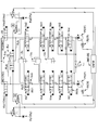
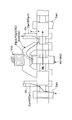
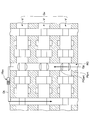
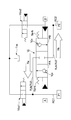
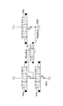
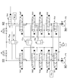
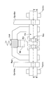
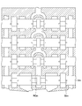
- FIG. 1 is a schematic external view illustrating an example of a construction machine according to an embodiment of the present invention. It is a hydraulic circuit diagram explaining an example of the hydraulic circuit of the construction machine which concerns on embodiment of this invention. It is explanatory drawing explaining an example of the direction control valve of the hydraulic circuit of the construction machine which concerns on embodiment of this invention. It is explanatory drawing explaining an example of the direction control valve of the hydraulic circuit of the construction machine which concerns on embodiment of this invention. It is explanatory drawing explaining an example of the direction control valve of the hydraulic circuit of the construction machine which concerns on embodiment of this invention. It is a schematic sectional drawing explaining an example of the cross section (AA cross section of FIG. 3A) of the direction control valve of the hydraulic circuit of the construction machine which concerns on embodiment of this invention.
- the present invention is a construction machine including a plurality of center bypass passages (center bypass lines) other than the present embodiment, and a part of pressure oil using a cut valve (bleed-off valve, flow control valve, etc.). Is returned to the tank (bleed-off control), and any oil that supplies (combines) the pressure oil supplied to one center bypass passage to the other center bypass passage can be used. Can also be used.
- Construction machines that can use the present invention include hydraulic excavators, crane trucks, bulldozers, wheel loaders and dump trucks, pile driving machines, pile removers, water jets, mud drainage treatment equipment, grout mixers, deep Includes foundation and drilling machines.
- Construction machine configuration A schematic configuration of a construction machine 100 in which the present invention can be used will be described with reference to FIG.
- the construction machine is a machine that performs a desired operation using a hydraulic actuator in the present embodiment.
- the construction machine 100 includes, as hydraulic actuators, a boom 11 whose base end is pivotally supported on the upper swing body 10Up, an arm 12 pivotally supported on the distal end of the boom 11, and a distal end of the arm 12. And a bucket 13 that is pivotally supported.
- the construction machine 100 extends and contracts the boom cylinder 11c in the longitudinal direction by supplying hydraulic oil (pressure oil) to the boom cylinder 11c of the boom 11. At this time, the boom 11 is driven in the vertical direction by expansion and contraction of the boom cylinder 11c. Further, the construction machine 100 is controlled by a boom direction control valve (for example, Vb1 and Vb2 in FIG. 2 described later) controlled in accordance with an operation amount (and an operation direction) of an operation lever of an operator (driver, operator). The hydraulic fluid supplied to the boom cylinder 11c is controlled. As a result, the construction machine 100 performs a desired operation according to the operation amount of the operation lever of the operator.
- a boom direction control valve for example, Vb1 and Vb2 in FIG. 2 described later
- the construction machine 100 drives the arm 12 and the bucket 13 by the expansion and contraction of the arm cylinder 12c and the bucket cylinder 13c as in the case of the boom 11.
- the construction machine 100 uses an arm direction control valve (for example, Va1 and Va2 in FIG. 2) and a bucket direction control valve (for example, Vbk in FIG. 2) to form an arm cylinder 12c and a bucket cylinder 13c.
- the hydraulic fluid supplied to the is controlled.
- the construction machine 100 travels (moves back and forth, left and right) and rotates (turns, etc.) the main body of the construction machine 100 using wheels and a turning device (for example, the lower traveling body 10Dw).
- the construction machine 100 uses, for example, a traveling direction control valve (for example, Vt1, Vt2, and Vst in FIG. 2) to run the construction machine 100 according to the amount of operation of the operation lever of the operator.
- a construction machine 100 that can use the present invention includes a hydraulic circuit (described later) 20 that supplies hydraulic oil (pressure oil) from a hydraulic pump to a hydraulic actuator, and a control device (described later) that controls the operation of each component of the construction machine 100. 30).
- the hydraulic circuit 20 of the construction machine 100 will be described with reference to FIG.
- the solid line described in FIG. 2 indicates an oil passage (pressure oil passage).
- a solid line added with // indicates an electric control system.
- the hydraulic circuit to which the present invention can be applied is not limited to that shown in FIG. That is, any hydraulic circuit having a plurality of center bypass passages and having a cut valve (bleed-off valve) disposed in the center bypass passage downstream of the plurality of directional control valves (direction control valve group).
- the present invention can also be applied to circuits. 2 includes two hydraulic pumps, the hydraulic circuit to which the present invention can be applied is not limited to one including two hydraulic pumps. That is, you may use this invention for a hydraulic circuit (construction machine) provided with three or more hydraulic pumps.
- the hydraulic circuit 20 of the construction machine 100 includes two hydraulic pumps mechanically connected to an output shaft of a power source (a prime mover, an engine, a motor, etc.) not shown.
- P first hydraulic pump P1 and second hydraulic pump P2
- two center bypass passages RC first center bypass passage RC1 to which the pressure oil discharged from each of the two hydraulic pumps P is supplied And a second center bypass passage RC2)
- a directional control valve such as the first traveling directional control valve Vt1 for controlling the hydraulic actuator (such as the boom 11 in FIG. 1)
- a directional control valve for traveling straight such as traveling). Direct valve
- the hydraulic circuit 20 includes a bleed-off valve Vbo (a first bleed-off valve Vbo1 and a second bleed-off valve Vbo2) disposed downstream (for example, the most downstream) of the center bypass passage RC. Further, the hydraulic circuit 20 includes a merging circuit RJ that supplies the pressure oil supplied to one center bypass passage of the plurality of center bypass passages to another center bypass passage (hereinafter referred to as “merging”).
- Vbo a first bleed-off valve Vbo1 and a second bleed-off valve Vbo2
- a directional control valve (Vt1 or the like) is arranged in series with the center bypass passage RC, and a bleed-off valve Vbo is arranged downstream of the center bypass passage RC.
- the hydraulic circuit 20 includes a first traveling direction control valve (for example, a left traveling direction control valve) Vt1 and a preliminary direction in a first center bypass passage RC1 corresponding to the first hydraulic pump P1.
- the control valve Vop, the turning direction control valve Vsw, the second boom direction control valve Vb2, the first arm direction control valve Va1, and the first bleed-off valve Vbo1 are arranged in series.
- the hydraulic circuit 20 includes a second traveling direction control valve (for example, a right traveling direction control valve) Vt2 and a bucket direction control valve Vbk in the second center bypass passage RC2 corresponding to the second hydraulic pump P2.
- the first boom direction control valve Vb1, the second arm direction control valve Va2, and the second bleed-off valve Vbo2 are arranged in series.
- the hydraulic circuit 20 has a straight running valve Vst disposed upstream of the second center bypass passage RC2.
- the hydraulic circuit 20 has a plurality of directional control valves arranged in series in the center bypass passage RC. Further, the hydraulic circuit 20 arranges the directional control valves in tandem by arranging a plurality of directional control valves in series in the two center bypass passages RC1, RC2. In the following description, a group composed of a plurality of directional control valves arranged in tandem in the center bypass passage RC is referred to as a “directional control valve group”.
- the hydraulic circuit 20 is a remote controller generated in accordance with operation information corresponding to the operation of the operator's operation lever (for example, information regarding the operation amount, information regarding the operation direction, hereinafter referred to as “operation information”).
- operation information for example, information regarding the operation amount, information regarding the operation direction, hereinafter referred to as “operation information”.
- the pressure (secondary pressure of the remote control valve) is input to the direction control valve (Vt1 or the like) corresponding to the operated operation lever.
- the direction control valve switches the position of the spool in accordance with the remote control pressure introduced at both ends of the spool (flow rate control spool), and the flow rate (operation amount) and direction (operation direction) of the pressure oil (hydraulic oil) To control.
- the hydraulic circuit 20 uses the bleed-off valve Vbo (for example, Vbo1) disposed downstream of the center bypass passage RC (for example, RC1), and the pressure oil discharged from the hydraulic pump P (for example, P1). Part (surplus) of the oil is returned to the hydraulic oil tank Tnk (bleed-off control is performed). Accordingly, the construction machine 100 can control the flow rate of the hydraulic oil (pressure oil) supplied to the hydraulic cylinder (for example, 11c), and can control the drive (operation) of the hydraulic actuator (for example, 11 in FIG. 1). .
- Vbo for example, Vbo1
- the bleed-off valve Vbo includes an unload position where the opening area is maximized and a block position where the opening area is zero.
- the bleed-off valve Vbo is switched from the unload position to the block position using the pressure oil of the pilot pump Pp controlled by the control device 30 described later, and its opening area is changed. Accordingly, the bleed-off valve Vbo can return (return) the pressure oil having a desired flow rate corresponding to the changed opening area to the hydraulic oil tank.
- the hydraulic circuit 20 of the construction machine 100 joins the pressure oil supplied to one center bypass passage to another center bypass passage using the joining circuit RJ.
- the merging circuit RJ is a merging direction control valve that controls the flow direction (hereinafter referred to as “inflow direction”) of the pressure oil supplied into the merging circuit RJ. Vj is provided.
- the merging circuit RJ uses pressure oil generated by using the pilot pump Pp (the first pilot pump Pp1 and the second pilot pump Pp2) as a pilot port (control port) of the merging direction control valve Vj. ). Accordingly, the hydraulic circuit 20 (merging circuit RJ) controls the merging direction control valve Vj.
- the merging circuit RJ uses the merging direction control valve Vj based on the operation information input by the operator using the operation lever to supply the pressure oil supplied to the center bypass passage RC1. It is possible to select (control) to join the center bypass passage RC2 or to join the pressure oil supplied to the center bypass passage RC2 to the center bypass passage RC1. That is, the hydraulic circuit 20 (joining circuit RJ) of the construction machine 100 according to the embodiment of the present invention can join the pressure oil in both directions of the center bypass passages RC1 and RC2.
- the hydraulic circuit 20 (merging circuit RJ) of the construction machine 100 in which the present invention can be used may be configured to merge the pressure oil into only one of the center bypass passage RC1 or RC2, for example.
- the hydraulic circuit 20 includes a directional control valve group (a plurality of directional control valves). Further, the directional control valve according to the present embodiment has, as the internal passage RV, a first internal passage that flows the supplied pressure oil to the center bypass passage RC, and a second that supplies the supplied pressure oil to the hydraulic actuator. And an internal passage. That is, the plurality of directional control valves constituting the directional control valve group are each provided with a first internal passage and a second internal passage.
- the opening of the first internal passage is not fully closed even when the spool position of the direction control valve is switched. That is, in the present embodiment, the first internal passage has substantially the same passage area regardless of the spool position of the direction control valve.
- the substantially same passage area means that the effective passage area through which the pressure oil actually passes does not change substantially compared to the increase / decrease amount of the passage area that changes due to the spool position displacement.
- the hydraulic circuit 20 of the construction machine 100 according to the embodiment of the present invention can form a parallel passage by the center bypass passage RC and the first internal passage. Further, the hydraulic circuit 20 according to the present embodiment can form a parallel passage corresponding to the passage area of the first internal passage. Furthermore, the hydraulic circuit 20 according to the present embodiment can supply pressure oil to the directional control valve group (a plurality of directional control valves) only from the formed parallel passage.
- the traveling direction control valves (for example, Vt1 and Vt2 in FIG. 2) among the plurality of direction control valves may have a configuration in which the opening of the first internal passage is fully closed (for example, RV1t in FIG. 2).
- the construction machine 100 (the hydraulic circuit 20 thereof) can ensure traveling stability (flow rate of hydraulic oil necessary for traveling) during traveling.
- the first internal passage (spool) of the directional control valve according to the present embodiment does not include a gap (hereinafter referred to as “bleed opening”) for returning the pressure oil to the hydraulic oil tank.
- bleed opening a gap
- the hydraulic circuit 20 according to the present embodiment can perform bleed-off control (unified bleed-off control) using the bleed-off valve Vbo disposed on the most downstream side of the center bypass passage RC. .
- the second internal passage according to the embodiment of the present invention is an internal passage (for example, RV2 in FIG. 2) for supplying pressure oil to a hydraulic cylinder (for example, the arm cylinder 12c in FIG. 2).
- the second internal passage supplies pressure oil discharged from the hydraulic pump P to a hydraulic cylinder (such as the arm cylinder 12c in FIG. 2).
- the second internal passage according to the present embodiment changes the path of the internal passage and supplies the hydraulic oil (hydraulic oil) supplied to the hydraulic cylinder. ) Is changed in flow rate (operation amount) and direction (operation direction).
- the direction control valve construction machine 100
- FIGS. 3A to 3C An example of the internal passage RV (spool shape) of the directional control valve disposed in the hydraulic circuit 20 of the construction machine 100 according to the embodiment of the present invention will be specifically described with reference to FIGS. 3A to 3C.
- the direction control valve (spool shape, etc.) that can be used in the present invention is not limited to that shown in FIGS. 3A to 3C.
- the directional control valve V of the hydraulic circuit 20 includes an inlet port PIprt supplied with pressure oil via a center bypass passage RC, and a pressure supplied from the inlet port PIprt.
- a check valve Vch is disposed at the inlet of the second internal passage RV2 to which pressure oil is supplied.
- the directional control valve V uses the check oil Vch to supply the pressure oil (working oil) Oc supplied from the center bypass passage RC when the spool is displaced (for example, Mb in the figure). And it supplies to a hydraulic cylinder (for example, 11c of FIG.1 and FIG.2) from cylinder port CprtB via 2nd internal channel
- the directional control valve V non-returns the pressure oil (working oil) Oc supplied from the center bypass passage RC when the spool is displaced (for example, Mc in the figure).
- a hydraulic cylinder (for example, 11c in FIGS. 1 and 2) is supplied from the cylinder port CprtB through the valve Vch and the second internal passage RV2.
- the pressure oil (hydraulic oil) Ot discharged from the hydraulic cylinder to the cylinder port CprtA is discharged from the tank port Tprt to the hydraulic oil tank.
- the hydraulic circuit 20 of the construction machine 100 does not perform bleed-off control in the directional control valve V (because the directional control valve V does not have a bleed opening).
- the opening area of the first internal passage RV1 of the direction control valve V can be increased.
- the direction control valve V according to the present embodiment can increase the opening area of the first internal passage RV1 of the direction control valve V, thereby reducing the pressure loss of the pressure oil passing through the center bypass passage RC. can do.
- the hydraulic circuit 20 of the construction machine 100 arranges a plurality of directional control valves V in series with the center bypass passage RC, whereby the center bypass passage RC and the plurality of first internal passages RV1 (directions).
- the passage formed by the control valve V) can function as a parallel passage.
- the hydraulic circuit 20 according to the present embodiment does not require a separate parallel passage, and can reduce the size of the direction control valve V (reducing the size of the spool in the axial direction and the radial direction).
- the hydraulic circuit 20 according to the present embodiment can reduce the size of the bridge passage Rb (FIG. 3A), for example.
- the hydraulic circuit 20 of the construction machine 100 according to the embodiment of the present invention uses a plurality of directional control valve groups V to flow pressure oil into the center bypass passage RC. That is, the hydraulic circuit 20 of the construction machine 100 according to the embodiment of the present invention flows the pressure oil into the center bypass passage RC (parallel passage) using the direction control valve group Gv.
- the hydraulic circuit 20 in which the directional control valve group Gv (a plurality of directional control valves V) is arranged has the same passage area regardless of the spool position of the directional control valve.
- a parallel passage can be formed by one internal passage and the center bypass passage RC.
- the hydraulic circuit 20 flows out the pressure oil Op supplied from the inlet port PIprt to the outlet port POprt via the first internal passage RV1 of the direction control valve V, and flows out to the center bypass passage RC.
- the hydraulic circuit 20 performs bleed-off control (unified bleed-off control) using a bleed-off valve Vbo disposed on the most downstream side of the center bypass passage RC.
- the hydraulic circuit 20 of the construction machine 100 does not need to provide a plurality of bleed openings in the spools of the plurality of directional control valves V (directional control valve group Gv).
- the shape of RC can be simplified.
- the hydraulic circuit 20 according to the present embodiment can reduce the bent portion of the center bypass passage RC, the pressure loss of the pressure oil passing through the center bypass passage RC can be reduced.
- the hydraulic circuit 20 of the construction machine 100 causes the passage formed by the center bypass passage RC and the first internal passage RV1 to function as a parallel passage, and the center bypass passage RC ( Since the pressure loss of the pressure oil passing through the center bypass passage RC can be reduced by simplifying the shape of the parallel passage), the pressure oil joined by the joining circuit RJ is supplied to a desired directional control valve.
- the center bypass passage RC parallel passage
- the center bypass passage RC parallel passage
- the hydraulic circuit 20 of the construction machine 100 uses the junction circuit RJ and the bleed-off valve Vbo (FIG. 2) to supply the pressure oil supplied to one center bypass passage to another center bypass passage. Merge.
- the junction circuit RJ according to the present embodiment includes a junction direction control valve Vj. Further, the junction circuit RJ according to the present embodiment further includes a check valve Vjc corresponding to the spool position (inflow direction) of the junction direction control valve Vj.
- the junction circuit RJ that can be used in the present invention is not limited to the junction circuit arranged on the upstream side of the bleed-off valve Vbo shown in FIG. That is, the merging circuit RJ that can be used in the present invention has an arbitrary position of the center bypass passage RC in the gap between the hydraulic pump P and the bleed-off valve Vbo (cut valve) (an arbitrary directional control valve of the directional control valve group). (Upstream side or downstream side).
- the junction circuit RJ that can be used in the present invention includes, for example, a center bypass passage RC1 immediately upstream of the preliminary directional control valve Vop and a center bypass passage immediately upstream of the bucket directional control valve Vbk as shown in FIG. 5B. Or between the center bypass passage RC1 immediately downstream of the preliminary directional control valve Vop and the center bypass passage RC2 immediately downstream of the bucket directional control valve Vbk as shown in FIG. 5C.
- a junction circuit RJ may be arranged.
- the merging circuit RJ is a hydraulic circuit as shown in FIG. 2
- the positions of the auxiliary direction control valve Vop and the turning direction control valve Vsw are switched, and the auxiliary direction control valve Vop and the bucket direction control are switched.
- the positional relationship may be such that the valve Vbk is adjacent.
- the merging circuit RJ controls the inflow direction of the pressure oil in the merging circuit RJ by changing the position of the spool of the merging direction control valve Vj.
- the merging circuit RJ inputs the pressure oil generated by using the pilot pump Pp (FIG. 2) to the pilot port (control port) of the merging direction control valve Vj, thereby setting the spool position of the merging direction control valve Vj. Control. Further, the merging circuit RJ supplies the pressure oil to the other center bypass passage (merges) using the pressure of the pressure oil in the one center bypass passage that has been raised by reducing the opening area of the bleed-off valve Vbo. ).
- the junction circuit RJ includes pilot pressures (discharge pressures of the pilot pump Pp) A and B generated based on operation information input to the construction machine 100. Are respectively input to the control ports of the merging direction control valve Vj.
- the merging direction control valve Vj displaces the position of the spool (for example, to the position PA or position PB in the figure) according to the pilot pressures A and B and the negative forces of the springs Spra and Sprb.
- the merging direction control valve Vj controls the inflow direction of the pressure oil in the merging circuit RJ.
- the junction circuit RJ according to the present embodiment uses the check valve Vjc to prevent the flow of pressure oil in the reverse direction with respect to the inflow direction.
- the junction circuit RJ reduces the pressure area of the bleed-off valve Vbo1 to reduce the pressure oil pressure in the center bypass passage RC1, for example, in order to join the pressure oil supplied to the center bypass passage RC1 to the center bypass passage RC2. It is possible to raise and to displace (Ra) the spool of the merging direction control valve Vj to the position PA.
- the junction circuit RJ reduces the opening area of the bleed-off valve Vbo2 by, for example, reducing the opening area of the bleed-off valve Vbo2 in order to join the pressure oil supplied to the center bypass passage RC2 to the center bypass passage RC1.
- the pressure can be increased and the spool of the merging direction control valve Vj can be displaced (Rb) to the position PB.
- the method of switching the spool position of the merging direction control valve Vj is not limited to the above direction (pressurizing method).
- the merging direction control valve Vj may be, for example, a solenoid valve (ON / OFF switching) or a combination of other (hydraulic pilot) mechanical mechanisms.
- the position of the spool of the merging direction control valve Vj is not limited to the above positions (position PA and position PB).
- the merging direction control valve Vj may be configured to eliminate the merging shock by switching proportionally regardless of the lever operation amount, for example.
- the check valve Vjc may be configured not to be built in the merging direction control valve Vj.
- the controller 30 of the construction machine 100 uses a controller 30C (FIG. 2) that is mounted to control the operation of the entire construction machine 100.
- the controller 30 ⁇ / b> C is a device that instructs each component of the construction machine 100 to operate and controls the operation of each component.
- the controller 30C (control device 30) can be configured by an arithmetic processing device including a CPU (Central Processing Unit) and a memory (ROM, RAM, etc.).
- the controller 30C controls the operation of the regulator R (R1, R2) based on the operation information (operation amount of the operation lever, operation direction, etc.) input to the construction machine 100. Control.
- the discharge amount of the hydraulic pump P (P1, P2) is controlled by the regulator R.
- the controller 30C generates a remote control pressure using a remote control valve or the like based on the operation information input to the construction machine 100.
- the controller 30C inputs the generated remote control pressure to the direction control valve (Vt1 or the like) using a remote control circuit (not shown).
- the direction control valve can switch the spool position and control the hydraulic oil supplied to the hydraulic actuator by using the input remote control pressure.
- the controller 30C controls the merging direction control valve Vj and the bleed-off valve Vbo based on information input to the construction machine 100.
- the controller 30C controls the discharge pressure of the pilot pump Pp that is input to the merging direction control valve Vj and the bleed-off valve Vbo, for example, according to a specific operation situation determined in advance, so that the spool of the merging direction control valve Vj is controlled.
- the position and the opening degree (opening area) of the bleed-off valve Vbo are controlled.
- the controller 30C can control the inflow direction of the junction circuit RJ and the pressure of the pressure oil flowing in.
- the control of the controller 30C is exemplified below.
- the controller 30C (control device 30), for example, at the time of preliminary priority, a center bypass passage (for example, a preliminary directional control valve Vop in FIG. 2) corresponding to a hydraulic actuator that prioritizes operation is disposed (for example, The pressure oil supplied to another center bypass passage (for example, RC2 in FIG. 2) can be joined to RC1) in FIG.
- the controller 30C can prioritize the operation of the spare hydraulic actuator.
- the controller 30C (control device 30) has a center bypass passage in which a directional control valve (Vbk in FIG. 2) corresponding to a hydraulic actuator (for example, the bucket 13 in FIG. 1) that gives priority to the operation is combined, for example, during a combined operation
- a directional control valve Vbk in FIG. 2 corresponding to a hydraulic actuator (for example, the bucket 13 in FIG. 1) that gives priority to the operation is combined, for example, during a combined operation
- the pressure oil supplied to the other center bypass passage (RC1 in FIG. 2) can be joined to (RC2 in FIG. 2).
- the controller 30C can give priority to the operation of the arbitrary hydraulic actuator (bucket 13) (increase the operation speed).
- the bleed-off control is not performed by the directional control valve, and the first internal passage of the directional control valve is used. Since the pressure oil discharged from the hydraulic pump P can be supplied downstream of the center bypass passage RC, the pressure loss of the pressure oil passing through the center bypass passage RC can be reduced. Further, according to the hydraulic circuit 20 of the construction machine 100 or the control device 30 thereof according to the embodiment of the present invention, the output port and the center bypass passage on the upstream side of the cut valve (bleed-off valve) when the junction circuit is formed.
- the inflow direction of the pressure oil in the merging circuit RJ is controlled using the merging direction control valve Vj and the bleed-off valve Vbo. Therefore, the pressure oil can be merged in both directions in the plurality of center bypass passages RC.
- the bleed-off control is performed by the directional control valve using the bleed-off valve Vbo disposed downstream of the center bypass passage RC. Without the bleed opening in each directional control valve, the bleed-off control can be performed downstream of the center bypass passage RC.
- the internal passage (for example, the first internal passage) of the directional control valve is compared with the case where the bleed-off control is performed by the plurality of directional control valves. ), The pressure loss of the pressure oil passing through the center bypass passage RC can be reduced.
- the directional control valve since the directional control valve is not provided with the bleed opening, the size of the directional control valve in the longitudinal direction can be reduced. it can.
- the direction control valve can be reduced in size compared to the case where the direction control valve is provided with a bleed opening, and the manufacture thereof is facilitated. can do.
- the plurality of directional control valves V are arranged in series in the center bypass passage RC, so that A passage formed by one internal passage RV1 (direction control valve V) can function as a parallel passage. Further, according to the hydraulic circuit 20 or the control device 30 thereof according to the present embodiment, the passage formed by the center bypass passage RC and the plurality of first internal passages RV1 can function as a parallel passage. There is no need to provide a separate passage, and the direction control valve V can be reduced in size.
- the bleed-off valve Vbo can be functioned as a cut valve (neutral cut valve) for the junction circuit RJ. There is no need to prepare.
- the hydraulic circuit 20 of the construction machine 100 or the control device 30 thereof according to the embodiment of the present invention has advantageous effects for downsizing, facilitating manufacture, and cost reduction of the construction machine 100 as a whole.
- FIG. 6 shows another example of the hydraulic circuit of the construction machine.
- bleed openings for example, Sbo of FIG. 7
- Va ⁇ b> 1, etc. of FIG. 6 can be provided in the spools of the directional control valves (Va ⁇ b> 1, etc. of FIG. 6) in order to perform bleed-off control. That is, the construction machine including the hydraulic circuit of FIG. 6 can perform bleed-off control by changing the opening area of the bleed opening.
- a cut valve Vct and an output port Pout are provided to allow pressure oil to flow out, and an input port Pin is further provided to allow the pressure oil to flow in (merge).
- the passage of the hydraulic circuit (for example, the passage connecting the output port Pout and the input port Pin) becomes complicated, and the pressure loss of the pressure oil may increase.
Landscapes
- Engineering & Computer Science (AREA)
- General Engineering & Computer Science (AREA)
- Mining & Mineral Resources (AREA)
- Civil Engineering (AREA)
- Structural Engineering (AREA)
- Physics & Mathematics (AREA)
- Fluid Mechanics (AREA)
- Mechanical Engineering (AREA)
- Fluid-Pressure Circuits (AREA)
- Operation Control Of Excavators (AREA)
Description
本発明を用いることができる建設機械100の概略構成を、図1を用いて説明する。ここで、建設機械とは、本実施形態では、油圧アクチュエータを用いて、所望の作業を実施する機械である。
本発明の実施形態に係る建設機械100の油圧回路20を、図2を用いて説明する。ここで、図2に記載した実線は、油路(圧油の通路)を示す。また、//を付加している実線は、電気制御系を示す。
本発明の実施形態に係る建設機械100の油圧回路20に配置された方向制御弁の内部通路RVを、下記に説明する。
本発明の実施形態に係る建設機械100の油圧回路20は、合流回路RJ及びブリードオフ弁Vbo(図2)を用いて、一のセンターバイパス通路に供給された圧油を他のセンターバイパス通路に合流させる。ここで、本実施形態に係る合流回路RJは、合流方向制御弁Vjを備える。また、本実施形態に係る合流回路RJは、合流方向制御弁Vjのスプールの位置(流入方向)に対応した逆止弁Vjcを更に備える。
建設機械100の制御装置30は、本実施形態では、建設機械100全体の動作を制御するために搭載されているコントローラ30C(図2)を用いる。ここで、コントローラ30C(制御装置30)は、建設機械100の各構成に動作を指示し、各構成の動作を制御する装置である。コントローラ30C(制御装置30)は、CPU(Central Processing Unit)及びメモリ(ROM、RAMなど)等を含む演算処理装置で構成することができる。
11 : ブーム
11c : ブームシリンダ
12 : アーム
12c : アームシリンダ
13 : バケット
13c : バケットシリンダ
20 : 油圧回路
30 : 制御手段
30C : コントローラ
Gv : 方向制御弁グループ
V : 方向制御弁(コントロールバルブ)
Va1,Va2,Vb1,Vb2,Vbk,Vsw,Vop,Vt1,Vt2:油圧アクチュエータ用方向制御弁
Vst : 走行直進用方向制御弁(走直弁)
Vbo : ブリードオフ弁(カット弁)
Vch,Vjc : 逆止弁
Vj : 合流方向制御弁(切換弁、比例切換弁など)
RJ,RJa,RJb: 合流回路
RC,RC1,RC2: センターバイパス通路(センターバイパスライン)
RV1 : 第1の内部通路(ブリードオフ用内部通路,PT開口用内部通路)
RV2 : 第2の内部通路(シリンダポート用内部通路)
PIprt:入口ポート
POprt:出口ポート
Tprt :タンクポート
Cprt,CprtA,CprtB :シリンダポート
P,P1,P2: 油圧ポンプ
R,R1,R2: レギュレータ
Tnk : 作動油タンク(タンク)
Pp,Pp1,Pp2: パイロットポンプ
Claims (8)
- 複数の油圧ポンプから吐出された圧油が夫々供給される複数のセンターバイパス通路を備える建設機械の油圧回路であって、
前記センターバイパス通路にタンデムに配置された複数の方向制御弁からなる方向制御弁グループと、
前記方向制御弁グループの下流の該センターバイパス通路に配置されたブリードオフ弁と、
複数の前記センターバイパス通路の一のセンターバイパス通路に供給された圧油を他のセンターバイパス通路に合流させる合流回路と
を有し、
前記方向制御弁は、該方向制御弁に供給された圧油を前記センターバイパス通路に流出する第1の内部通路と、該方向制御弁に供給された圧油を前記建設機械の油圧アクチュエータに供給する第2の内部通路とを備え、
前記第1の内部通路は、前記油圧ポンプから吐出された圧油を該方向制御弁に対して下流の該センターバイパス通路に流出させることにより、該センターバイパス通路と該第1の内部通路とによってパラレル通路を形成し、
前記ブリードオフ弁は、該ブリードオフ弁の開口面積を変化させることによって、前記パラレル通路を介して供給される圧油をブリードオフ制御し、
前記合流回路は、合流させる圧油の流入方向を制御する合流方向制御弁を備える、
ことを特徴とする建設機械の油圧回路。 - 前記第1の内部通路は、前記方向制御弁のスプール位置に関わらず略同一の通路面積を有し、該通路面積に対応する前記パラレル通路を形成し、
前記方向制御弁グループは、前記パラレル通路のみから圧油の供給を受ける、
ことを特徴とする、請求項1に記載の建設機械の油圧回路。 - 複数の前記油圧ポンプは、2つの油圧ポンプであり、
複数の前記センターバイパス通路は、2つのセンターバイパス通路であり、
前記合流方向制御弁は、前記流入方向を切り換えることによって、前記2つのセンターバイパス通路に夫々供給された圧油のいずれか一方の圧油を他方の圧油が供給されたセンターバイパス通路に供給する、
ことを特徴とする、請求項1に記載の建設機械の油圧回路。 - 前記合流回路は、前記流入方向に対応する逆止弁を更に有し、
前記逆止弁は、前記流入方向に対して逆方向の圧油の流れを防止する、
ことを特徴とする、請求項1に記載の建設機械の油圧回路。 - 請求項1に記載の建設機械の油圧回路を制御する建設機械の油圧回路の制御装置。
- 前記建設機械に入力された操作情報に応じて、前記流入方向を変更する、ことを特徴とする、請求項5に記載の建設機械の油圧回路の制御装置。
- 前記合流回路を用いて圧油を合流させる場合に、前記ブリードオフ弁の前記開口面積を減少させる、ことを特徴とする、請求項5に記載の建設機械の油圧回路の制御装置。
- 前記合流回路を用いて圧油を合流させることによって、合流した圧油が供給される前記方向制御弁に対応する油圧アクチュエータの操作を優先する、ことを特徴とする、請求項5に記載の建設機械の油圧回路の制御装置。
Priority Applications (4)
| Application Number | Priority Date | Filing Date | Title |
|---|---|---|---|
| EP13813005.9A EP2868930B1 (en) | 2012-07-02 | 2013-04-11 | Hydraulic circuit for construction machine and control device for same |
| CN201380020035.5A CN104246235B (zh) | 2012-07-02 | 2013-04-11 | 施工机械的液压回路及其控制装置 |
| KR1020147028305A KR101642899B1 (ko) | 2012-07-02 | 2013-04-11 | 건설기계의 유압회로 및 그 제어장치 |
| US14/525,322 US9725884B2 (en) | 2012-07-02 | 2014-10-28 | Hydraulic circuit for construction machine and control device for same |
Applications Claiming Priority (2)
| Application Number | Priority Date | Filing Date | Title |
|---|---|---|---|
| JP2012-148928 | 2012-07-02 | ||
| JP2012148928A JP5985276B2 (ja) | 2012-07-02 | 2012-07-02 | 建設機械の油圧回路及びその制御装置 |
Related Child Applications (1)
| Application Number | Title | Priority Date | Filing Date |
|---|---|---|---|
| US14/525,322 Continuation US9725884B2 (en) | 2012-07-02 | 2014-10-28 | Hydraulic circuit for construction machine and control device for same |
Publications (1)
| Publication Number | Publication Date |
|---|---|
| WO2014006950A1 true WO2014006950A1 (ja) | 2014-01-09 |
Family
ID=49881715
Family Applications (1)
| Application Number | Title | Priority Date | Filing Date |
|---|---|---|---|
| PCT/JP2013/060959 Ceased WO2014006950A1 (ja) | 2012-07-02 | 2013-04-11 | 建設機械の油圧回路及びその制御装置 |
Country Status (6)
| Country | Link |
|---|---|
| US (1) | US9725884B2 (ja) |
| EP (1) | EP2868930B1 (ja) |
| JP (1) | JP5985276B2 (ja) |
| KR (1) | KR101642899B1 (ja) |
| CN (1) | CN104246235B (ja) |
| WO (1) | WO2014006950A1 (ja) |
Cited By (1)
| Publication number | Priority date | Publication date | Assignee | Title |
|---|---|---|---|---|
| WO2016098185A1 (ja) * | 2014-12-16 | 2016-06-23 | Kyb株式会社 | 建設機械の流体圧制御装置 |
Families Citing this family (17)
| Publication number | Priority date | Publication date | Assignee | Title |
|---|---|---|---|---|
| US10184499B2 (en) * | 2013-07-24 | 2019-01-22 | Volvo Construction Equipment Ab | Hydraulic circuit for construction machine |
| KR101530886B1 (ko) * | 2015-02-09 | 2015-06-24 | 덕산네오룩스 주식회사 | 유기전기소자용 신규 화합물, 이를 이용한 유기전기소자 및 그 전자장치 |
| JP6456277B2 (ja) * | 2015-12-18 | 2019-01-23 | 日立建機株式会社 | 建設機械 |
| JP6304273B2 (ja) | 2016-02-05 | 2018-04-04 | コベルコ建機株式会社 | 作業機械の油圧駆動装置 |
| KR102357613B1 (ko) * | 2016-07-29 | 2022-01-28 | 스미토모 겐키 가부시키가이샤 | 쇼벨, 쇼벨용 컨트롤밸브 |
| WO2017014324A1 (ja) * | 2016-07-29 | 2017-01-26 | 株式会社小松製作所 | 制御システム、作業機械、及び制御方法 |
| US11408145B2 (en) * | 2016-09-21 | 2022-08-09 | Komatsu Ltd. | Work vehicle and hydraulic control method |
| GB2554683B (en) * | 2016-10-03 | 2022-01-26 | Bamford Excavators Ltd | Hydraulic systems for construction machinery |
| GB2554682B (en) | 2016-10-03 | 2022-01-19 | Bamford Excavators Ltd | Hydraulic systems for construction machinery |
| JP7034686B2 (ja) | 2017-11-30 | 2022-03-14 | キヤノンメディカルシステムズ株式会社 | 超音波診断装置、医用画像処理装置及びそのプログラム |
| JP7289794B2 (ja) * | 2017-12-07 | 2023-06-12 | 住友建機株式会社 | ショベル |
| JP7227830B2 (ja) * | 2019-03-30 | 2023-02-22 | 住友建機株式会社 | ショベル |
| US11624452B2 (en) | 2019-04-12 | 2023-04-11 | Barko Hydraulics, LLC | System for adjusting rate of spool centering in a pilot-controlled hydraulic spool valve |
| JP7182579B2 (ja) * | 2020-03-27 | 2022-12-02 | 日立建機株式会社 | 作業機械 |
| US11001989B1 (en) * | 2020-03-30 | 2021-05-11 | Caterpillar Inc. | Electrical control of a hydraulic system |
| US12559910B2 (en) * | 2020-12-24 | 2026-02-24 | Hitachi Construction Machinery Co., Ltd. | Work machine |
| US12352014B2 (en) | 2023-12-04 | 2025-07-08 | Caterpillar Inc. | Enhanced electrical control of a hydraulic system |
Citations (8)
| Publication number | Priority date | Publication date | Assignee | Title |
|---|---|---|---|---|
| JPH02248706A (ja) * | 1989-03-22 | 1990-10-04 | Komatsu Ltd | 油圧回路 |
| JPH1018359A (ja) * | 1996-06-28 | 1998-01-20 | Yutani Heavy Ind Ltd | 建設機械の制御回路 |
| JPH10147959A (ja) * | 1996-11-20 | 1998-06-02 | Yutani Heavy Ind Ltd | 油圧モータの制御装置 |
| JPH11107328A (ja) * | 1997-10-02 | 1999-04-20 | Kobe Steel Ltd | 油圧ショベルの油圧制御装置 |
| JPH11257302A (ja) | 1998-03-06 | 1999-09-21 | Toshiba Mach Co Ltd | 多連油圧バルブ |
| JP2000009102A (ja) * | 1998-06-22 | 2000-01-11 | Kobe Steel Ltd | 油圧アクチュエータの制御装置 |
| JP2007120004A (ja) * | 2005-10-24 | 2007-05-17 | Kobelco Contstruction Machinery Ltd | 作業機械の油圧制御装置 |
| JP2007285520A (ja) * | 2006-04-18 | 2007-11-01 | Volvo Construction Equipment Ab | 走行直進用油圧回路 |
Family Cites Families (9)
| Publication number | Priority date | Publication date | Assignee | Title |
|---|---|---|---|---|
| JPS6138204A (ja) | 1984-07-30 | 1986-02-24 | Toshiba Mach Co Ltd | 多連油圧切換弁のための多連パイロツト弁 |
| JP2740223B2 (ja) | 1989-01-09 | 1998-04-15 | 日立建機株式会社 | 弁装置 |
| US5941155A (en) * | 1996-11-20 | 1999-08-24 | Kabushiki Kaisha Kobe Seiko Sho | Hydraulic motor control system |
| JP3943779B2 (ja) * | 1999-01-19 | 2007-07-11 | 日立建機株式会社 | 土木・建設機械の油圧駆動装置 |
| JP4096901B2 (ja) * | 2004-03-17 | 2008-06-04 | コベルコ建機株式会社 | 作業機械の油圧制御装置 |
| JP4578207B2 (ja) | 2004-11-08 | 2010-11-10 | カヤバ工業株式会社 | 弁装置 |
| JP4232784B2 (ja) * | 2006-01-20 | 2009-03-04 | コベルコ建機株式会社 | 作業機械の油圧制御装置 |
| JP4353190B2 (ja) * | 2006-02-27 | 2009-10-28 | コベルコ建機株式会社 | 建設機械の油圧回路 |
| EP2157245B1 (en) * | 2008-08-21 | 2021-03-17 | Volvo Construction Equipment AB | Hydraulic system for construction equipment |
-
2012
- 2012-07-02 JP JP2012148928A patent/JP5985276B2/ja not_active Expired - Fee Related
-
2013
- 2013-04-11 CN CN201380020035.5A patent/CN104246235B/zh active Active
- 2013-04-11 EP EP13813005.9A patent/EP2868930B1/en active Active
- 2013-04-11 KR KR1020147028305A patent/KR101642899B1/ko not_active Expired - Fee Related
- 2013-04-11 WO PCT/JP2013/060959 patent/WO2014006950A1/ja not_active Ceased
-
2014
- 2014-10-28 US US14/525,322 patent/US9725884B2/en active Active
Patent Citations (8)
| Publication number | Priority date | Publication date | Assignee | Title |
|---|---|---|---|---|
| JPH02248706A (ja) * | 1989-03-22 | 1990-10-04 | Komatsu Ltd | 油圧回路 |
| JPH1018359A (ja) * | 1996-06-28 | 1998-01-20 | Yutani Heavy Ind Ltd | 建設機械の制御回路 |
| JPH10147959A (ja) * | 1996-11-20 | 1998-06-02 | Yutani Heavy Ind Ltd | 油圧モータの制御装置 |
| JPH11107328A (ja) * | 1997-10-02 | 1999-04-20 | Kobe Steel Ltd | 油圧ショベルの油圧制御装置 |
| JPH11257302A (ja) | 1998-03-06 | 1999-09-21 | Toshiba Mach Co Ltd | 多連油圧バルブ |
| JP2000009102A (ja) * | 1998-06-22 | 2000-01-11 | Kobe Steel Ltd | 油圧アクチュエータの制御装置 |
| JP2007120004A (ja) * | 2005-10-24 | 2007-05-17 | Kobelco Contstruction Machinery Ltd | 作業機械の油圧制御装置 |
| JP2007285520A (ja) * | 2006-04-18 | 2007-11-01 | Volvo Construction Equipment Ab | 走行直進用油圧回路 |
Non-Patent Citations (1)
| Title |
|---|
| See also references of EP2868930A4 |
Cited By (1)
| Publication number | Priority date | Publication date | Assignee | Title |
|---|---|---|---|---|
| WO2016098185A1 (ja) * | 2014-12-16 | 2016-06-23 | Kyb株式会社 | 建設機械の流体圧制御装置 |
Also Published As
| Publication number | Publication date |
|---|---|
| CN104246235B (zh) | 2017-07-14 |
| CN104246235A (zh) | 2014-12-24 |
| KR20140138267A (ko) | 2014-12-03 |
| JP5985276B2 (ja) | 2016-09-06 |
| KR101642899B1 (ko) | 2016-07-26 |
| JP2014009794A (ja) | 2014-01-20 |
| US9725884B2 (en) | 2017-08-08 |
| EP2868930A1 (en) | 2015-05-06 |
| US20150040552A1 (en) | 2015-02-12 |
| EP2868930B1 (en) | 2017-03-08 |
| EP2868930A4 (en) | 2016-01-13 |
Similar Documents
| Publication | Publication Date | Title |
|---|---|---|
| JP5985276B2 (ja) | 建設機械の油圧回路及びその制御装置 | |
| JP5758348B2 (ja) | 建設機械の油圧回路 | |
| JP5778086B2 (ja) | 建設機械の油圧回路及びその制御装置 | |
| JP2010013927A (ja) | 掘削機用油圧駆動システム | |
| JP5978056B2 (ja) | 建設機械の油圧回路及びその制御装置 | |
| JP6453820B2 (ja) | 建設機械用方向制御弁グループ | |
| KR101844170B1 (ko) | 건설 기계의 유체압 제어 장치 | |
| JP6763006B2 (ja) | ショベル及び建設機械用方向制御弁グループ | |
| CN111692146A (zh) | 控制阀和建设机械用液压系统 |
Legal Events
| Date | Code | Title | Description |
|---|---|---|---|
| 121 | Ep: the epo has been informed by wipo that ep was designated in this application |
Ref document number: 13813005 Country of ref document: EP Kind code of ref document: A1 |
|
| ENP | Entry into the national phase |
Ref document number: 20147028305 Country of ref document: KR Kind code of ref document: A |
|
| REEP | Request for entry into the european phase |
Ref document number: 2013813005 Country of ref document: EP |
|
| WWE | Wipo information: entry into national phase |
Ref document number: 2013813005 Country of ref document: EP |
|
| NENP | Non-entry into the national phase |
Ref country code: DE |