WO2014010507A1 - 移動ユニット - Google Patents
移動ユニット Download PDFInfo
- Publication number
- WO2014010507A1 WO2014010507A1 PCT/JP2013/068387 JP2013068387W WO2014010507A1 WO 2014010507 A1 WO2014010507 A1 WO 2014010507A1 JP 2013068387 W JP2013068387 W JP 2013068387W WO 2014010507 A1 WO2014010507 A1 WO 2014010507A1
- Authority
- WO
- WIPO (PCT)
- Prior art keywords
- track
- movable body
- guide
- moving
- track rail
- Prior art date
- Legal status (The legal status is an assumption and is not a legal conclusion. Google has not performed a legal analysis and makes no representation as to the accuracy of the status listed.)
- Ceased
Links
Images


Classifications
-
- F—MECHANICAL ENGINEERING; LIGHTING; HEATING; WEAPONS; BLASTING
- F16—ENGINEERING ELEMENTS AND UNITS; GENERAL MEASURES FOR PRODUCING AND MAINTAINING EFFECTIVE FUNCTIONING OF MACHINES OR INSTALLATIONS; THERMAL INSULATION IN GENERAL
- F16M—FRAMES, CASINGS OR BEDS OF ENGINES, MACHINES OR APPARATUS, NOT SPECIFIC TO ENGINES, MACHINES OR APPARATUS PROVIDED FOR ELSEWHERE; STANDS; SUPPORTS
- F16M13/00—Other supports for positioning apparatus or articles; Means for steadying hand-held apparatus or articles
- F16M13/02—Other supports for positioning apparatus or articles; Means for steadying hand-held apparatus or articles for supporting on, or attaching to, an object, e.g. tree, gate, window-frame, cycle
- F16M13/022—Other supports for positioning apparatus or articles; Means for steadying hand-held apparatus or articles for supporting on, or attaching to, an object, e.g. tree, gate, window-frame, cycle repositionable
-
- F—MECHANICAL ENGINEERING; LIGHTING; HEATING; WEAPONS; BLASTING
- F16—ENGINEERING ELEMENTS AND UNITS; GENERAL MEASURES FOR PRODUCING AND MAINTAINING EFFECTIVE FUNCTIONING OF MACHINES OR INSTALLATIONS; THERMAL INSULATION IN GENERAL
- F16C—SHAFTS; FLEXIBLE SHAFTS; ELEMENTS OR CRANKSHAFT MECHANISMS; ROTARY BODIES OTHER THAN GEARING ELEMENTS; BEARINGS
- F16C29/00—Bearings for parts moving only linearly
- F16C29/004—Fixing of a carriage or rail, e.g. rigid mounting to a support structure or a movable part
-
- B—PERFORMING OPERATIONS; TRANSPORTING
- B64—AIRCRAFT; AVIATION; COSMONAUTICS
- B64D—EQUIPMENT FOR FITTING IN OR TO AIRCRAFT; FLIGHT SUITS; PARACHUTES; ARRANGEMENT OR MOUNTING OF POWER PLANTS OR PROPULSION TRANSMISSIONS IN AIRCRAFT
- B64D11/00—Passenger or crew accommodation; Flight-deck installations not otherwise provided for
-
- F—MECHANICAL ENGINEERING; LIGHTING; HEATING; WEAPONS; BLASTING
- F16—ENGINEERING ELEMENTS AND UNITS; GENERAL MEASURES FOR PRODUCING AND MAINTAINING EFFECTIVE FUNCTIONING OF MACHINES OR INSTALLATIONS; THERMAL INSULATION IN GENERAL
- F16C—SHAFTS; FLEXIBLE SHAFTS; ELEMENTS OR CRANKSHAFT MECHANISMS; ROTARY BODIES OTHER THAN GEARING ELEMENTS; BEARINGS
- F16C29/00—Bearings for parts moving only linearly
- F16C29/008—Systems with a plurality of bearings, e.g. four carriages supporting a slide on two parallel rails
-
- F—MECHANICAL ENGINEERING; LIGHTING; HEATING; WEAPONS; BLASTING
- F16—ENGINEERING ELEMENTS AND UNITS; GENERAL MEASURES FOR PRODUCING AND MAINTAINING EFFECTIVE FUNCTIONING OF MACHINES OR INSTALLATIONS; THERMAL INSULATION IN GENERAL
- F16C—SHAFTS; FLEXIBLE SHAFTS; ELEMENTS OR CRANKSHAFT MECHANISMS; ROTARY BODIES OTHER THAN GEARING ELEMENTS; BEARINGS
- F16C29/00—Bearings for parts moving only linearly
- F16C29/04—Ball or roller bearings
- F16C29/06—Ball or roller bearings in which the rolling bodies circulate partly without carrying load
- F16C29/0614—Ball or roller bearings in which the rolling bodies circulate partly without carrying load with a shoe type bearing body, e.g. a body facing one side of the guide rail or track only
- F16C29/0621—Ball or roller bearings in which the rolling bodies circulate partly without carrying load with a shoe type bearing body, e.g. a body facing one side of the guide rail or track only for supporting load in essentially two directions, e.g. by multiple points of contact or two rows of rolling elements
- F16C29/0623—Ball or roller bearings in which the rolling bodies circulate partly without carrying load with a shoe type bearing body, e.g. a body facing one side of the guide rail or track only for supporting load in essentially two directions, e.g. by multiple points of contact or two rows of rolling elements with balls
-
- F—MECHANICAL ENGINEERING; LIGHTING; HEATING; WEAPONS; BLASTING
- F16—ENGINEERING ELEMENTS AND UNITS; GENERAL MEASURES FOR PRODUCING AND MAINTAINING EFFECTIVE FUNCTIONING OF MACHINES OR INSTALLATIONS; THERMAL INSULATION IN GENERAL
- F16M—FRAMES, CASINGS OR BEDS OF ENGINES, MACHINES OR APPARATUS, NOT SPECIFIC TO ENGINES, MACHINES OR APPARATUS PROVIDED FOR ELSEWHERE; STANDS; SUPPORTS
- F16M11/00—Stands or trestles as supports for apparatus or articles placed thereon ; Stands for scientific apparatus such as gravitational force meters
- F16M11/02—Heads
- F16M11/04—Means for attachment of apparatus; Means allowing adjustment of the apparatus relatively to the stand
- F16M11/043—Allowing translations
-
- F—MECHANICAL ENGINEERING; LIGHTING; HEATING; WEAPONS; BLASTING
- F16—ENGINEERING ELEMENTS AND UNITS; GENERAL MEASURES FOR PRODUCING AND MAINTAINING EFFECTIVE FUNCTIONING OF MACHINES OR INSTALLATIONS; THERMAL INSULATION IN GENERAL
- F16M—FRAMES, CASINGS OR BEDS OF ENGINES, MACHINES OR APPARATUS, NOT SPECIFIC TO ENGINES, MACHINES OR APPARATUS PROVIDED FOR ELSEWHERE; STANDS; SUPPORTS
- F16M11/00—Stands or trestles as supports for apparatus or articles placed thereon ; Stands for scientific apparatus such as gravitational force meters
- F16M11/42—Stands or trestles as supports for apparatus or articles placed thereon ; Stands for scientific apparatus such as gravitational force meters with arrangement for propelling the support stands on wheels
- F16M11/425—Stands or trestles as supports for apparatus or articles placed thereon ; Stands for scientific apparatus such as gravitational force meters with arrangement for propelling the support stands on wheels along guiding means
-
- F—MECHANICAL ENGINEERING; LIGHTING; HEATING; WEAPONS; BLASTING
- F16—ENGINEERING ELEMENTS AND UNITS; GENERAL MEASURES FOR PRODUCING AND MAINTAINING EFFECTIVE FUNCTIONING OF MACHINES OR INSTALLATIONS; THERMAL INSULATION IN GENERAL
- F16M—FRAMES, CASINGS OR BEDS OF ENGINES, MACHINES OR APPARATUS, NOT SPECIFIC TO ENGINES, MACHINES OR APPARATUS PROVIDED FOR ELSEWHERE; STANDS; SUPPORTS
- F16M13/00—Other supports for positioning apparatus or articles; Means for steadying hand-held apparatus or articles
- F16M13/02—Other supports for positioning apparatus or articles; Means for steadying hand-held apparatus or articles for supporting on, or attaching to, an object, e.g. tree, gate, window-frame, cycle
- F16M13/027—Ceiling supports
-
- B—PERFORMING OPERATIONS; TRANSPORTING
- B64—AIRCRAFT; AVIATION; COSMONAUTICS
- B64D—EQUIPMENT FOR FITTING IN OR TO AIRCRAFT; FLIGHT SUITS; PARACHUTES; ARRANGEMENT OR MOUNTING OF POWER PLANTS OR PROPULSION TRANSMISSIONS IN AIRCRAFT
- B64D2231/00—Emergency oxygen systems
- B64D2231/02—Supply or distribution systems
- B64D2231/025—Oxygen masks; Mask storages; Features related to mask deployment
-
- F—MECHANICAL ENGINEERING; LIGHTING; HEATING; WEAPONS; BLASTING
- F16—ENGINEERING ELEMENTS AND UNITS; GENERAL MEASURES FOR PRODUCING AND MAINTAINING EFFECTIVE FUNCTIONING OF MACHINES OR INSTALLATIONS; THERMAL INSULATION IN GENERAL
- F16C—SHAFTS; FLEXIBLE SHAFTS; ELEMENTS OR CRANKSHAFT MECHANISMS; ROTARY BODIES OTHER THAN GEARING ELEMENTS; BEARINGS
- F16C2326/00—Articles relating to transporting
- F16C2326/43—Aeroplanes; Helicopters
-
- F—MECHANICAL ENGINEERING; LIGHTING; HEATING; WEAPONS; BLASTING
- F16—ENGINEERING ELEMENTS AND UNITS; GENERAL MEASURES FOR PRODUCING AND MAINTAINING EFFECTIVE FUNCTIONING OF MACHINES OR INSTALLATIONS; THERMAL INSULATION IN GENERAL
- F16C—SHAFTS; FLEXIBLE SHAFTS; ELEMENTS OR CRANKSHAFT MECHANISMS; ROTARY BODIES OTHER THAN GEARING ELEMENTS; BEARINGS
- F16C29/00—Bearings for parts moving only linearly
- F16C29/04—Ball or roller bearings
- F16C29/06—Ball or roller bearings in which the rolling bodies circulate partly without carrying load
- F16C29/063—Ball or roller bearings in which the rolling bodies circulate partly without carrying load with a bearing body, e.g. a carriage or part thereof, provided between the legs of a U-shaped guide rail or track
-
- F—MECHANICAL ENGINEERING; LIGHTING; HEATING; WEAPONS; BLASTING
- F16—ENGINEERING ELEMENTS AND UNITS; GENERAL MEASURES FOR PRODUCING AND MAINTAINING EFFECTIVE FUNCTIONING OF MACHINES OR INSTALLATIONS; THERMAL INSULATION IN GENERAL
- F16M—FRAMES, CASINGS OR BEDS OF ENGINES, MACHINES OR APPARATUS, NOT SPECIFIC TO ENGINES, MACHINES OR APPARATUS PROVIDED FOR ELSEWHERE; STANDS; SUPPORTS
- F16M2200/00—Details of stands or supports
- F16M2200/02—Locking means
- F16M2200/025—Locking means for translational movement
- F16M2200/028—Locking means for translational movement by positive interaction, e.g. male-female connections
Definitions
- the present invention relates to a moving unit that freely guides movable bodies such as various units and tables along a pair of guide tracks laid parallel to each other with respect to a fixed portion.
- the moving unit disclosed in the publication is used for the purpose of freely moving furniture, electrical appliances, etc. on the wall surface of the building, and is laid parallel to each other on the wall surface and the rolling elements along the longitudinal direction.
- a movable body guided along the track rail on the wall surface may be a base plate for fixing an electrical appliance such as a television or furniture, or may be a housing of the electrical appliance itself. According to the moving unit, the movable body is placed on a wall surface. Can be moved freely.
- this type of mobile unit in a wide space such as in an aircraft, ship or train cabin, various devices, interiors, etc. are moved to an arbitrary position in the space.
- a service unit is provided for each seat, and in addition to storing emergency equipment such as oxygen masks in this service unit, equipment such as seat number display and reading lights Kind is attached. If this service unit can be moved along the ceiling surface in the guest room and fixed at an arbitrary position, it is possible to extremely easily change the arrangement pitch of the seats in the guest room.
- a plurality of track rails are arranged in series to form a long guide track, and the guide block is connected while the moving block is connected to the track rail. It is necessary to move along the trajectory.
- a large structure such as an aircraft or a ship is manufactured by dividing it into a plurality of divided bodies, and finally, the desired large structure is often completed by combining these divided bodies.
- it is difficult to think of fixing the track rail so as to straddle the joint portion between adjacent divided bodies.
- part of the interior work is performed on the divided fuselage before assembling the fuselage, and the interior work for each fuselage is performed. After completion to some extent, the fuselage is assembled by joining multiple fuselage.
- Patent Document 1 As an example of a device for guiding a movable body to an arbitrary position along a fixed path, the moving unit shown in Patent Document 1 has been described as an example.
- the above-described problem is a low friction property.
- a moving block with a sliding contact member slides on the track rail, or a moving block having a pivoted wheel rotates on the track rail and moves on the track rail. It is done.
- the present invention has been made in view of such a problem.
- the object of the present invention is to form a guide track that guides the movable body by arranging a plurality of track rails in series. It is an object of the present invention to provide a moving unit capable of smoothly moving on a guide track over a joint of the track rail, and thereby smoothly moving a movable body with respect to a fixed portion.
- the present invention includes a pair of guide tracks laid parallel to each other with respect to the fixed portion, and a plurality of moving blocks assembled to at least two guide tracks and movable along the guide tracks.
- a moving unit fixed to the moving block and movable on the fixed portion, and each guide track has a plurality of track rails each having a guide surface along the longitudinal direction.
- the moving block has a contact that travels on the guide surface while passing through joint gaps of a plurality of track rails arranged in series. And regarding the joint gaps of the plurality of track rails included in the pair of guide tracks, when the moving block is positioned on any one joint gap, the other joint gap
- the moving block is configured not to be positioned.
- the present invention among the plurality of moving members assembled to each of the pair of guide tracks, in a state where one moving member is positioned on the joint gap of the track rails arranged in series, Since the remaining moving members assembled in the guide track are not located on the joint gap of the track rail, when moving the movable body along the guide track, at least three or more moving blocks are provided.
- the load that acts on the movable body without being present on the joint gap of the track rail is loaded, and the movable body supported by the moving block climbs over the joint of the track rail and is in a stable posture. It is possible to reciprocate along the guide track.
- FIG. 1 shows an example of how the mobile unit is used according to an embodiment of the present invention.
- the service unit 42 is arranged on the ceiling panel 101 of the cabin 100 corresponding to the passenger seat 102.
- the service unit 42 accommodates disaster prevention tools such as an oxygen mask and various display devices such as a seat number display and a reading lamp.
- the aircraft manufacturer arranges the seats 102 in the cabin 100 so as to meet the specifications required by the airline. is doing. For this reason, for the aircraft manufacturer, the arrangement of the service units 42 can be freely adjusted according to the arrangement interval of the seats 102, and the service units 42 can be adjusted according to the increase or decrease of the number of seats.
- the convenience in assembling the aircraft is improved. Further, since the service unit 42 also stores disaster prevention equipment, the service unit 42 itself needs to be periodically inspected and maintained. From this point of view, if the service unit 42 can be freely attached and detached, the aircraft operating the aircraft The convenience of the company is also improved.
- the mobile unit of the present invention satisfies such a requirement, and the service unit 42 is movably disposed with respect to the ceiling panel 101 as a fixed portion, and the service unit is placed at an arbitrary position of the ceiling panel 101. 42 can be fixed. In addition, the service unit 42 can be freely attached to and detached from the ceiling panel 101 as a fixed portion.
- FIG. 2 and 3 show an example of an embodiment of the mobile unit 1 to which the present invention is applied.
- FIG. 2 is a perspective view showing a state in which the service unit 24 is supported with respect to a ceiling panel 101 as a fixed part using the mobile unit 1, and
- FIG. 3 shows a main part of the mobile unit 1 with the ceiling panel 101 removed. It is the shown perspective view.
- the moving unit 1 includes a pair of guide tracks 2 laid in parallel to a ceiling panel 101 as a fixed portion in an aircraft cabin 100, and a plurality of moving blocks 3 assembled to each track guide track 2. These movable blocks 3 are fixed to a movable body 41.
- Each guide track 2 is configured by laying a plurality of track rails 21 formed in a straight line in series. By increasing the number of track rails 21 laid in series, the length corresponding to the total length of the ceiling panel 101 is obtained. It is possible to configure a long guide track 2. Further, by arranging a plurality of ceiling panels 101 in series, a longer guide track 2 can be configured.
- Each track rail 21 has a guide surface 25 for guiding the moving block 3 along the longitudinal direction thereof. When the plurality of track rails 21 are laid in series, the guide surfaces 25 of the track rails 21 are straight. A single guide surface that is continuous in the shape and extends over the entire length of the guide track 2 is formed.
- the pair of guide tracks 2 are arranged with the guide surfaces 25 facing each other, and the moving block 3 fixed to the movable body 41 is located inside the pair of guide tracks 2. It is assembled toward the outside.
- Each moving block 3 includes a contact that travels on the guide surface 25 of the track rail 21, and the moving block 21 loads the load acting on the movable body 41 by the action of the contact, and the track It is possible to move freely along the rail 21.
- the moving block 21 can freely move over the entire length of the guide track 2 while sequentially transferring a plurality of track rails 21 laid in series.
- the movable body 41 fixed to the moving block 3 can move freely along the guide track 2.
- the service unit 42 is elongated. It can be freely moved to any position on the ceiling panel 101.
- the movable body 41 is formed of a metal material or a resin material.
- the moving block 3 is fixed to a plate-shaped movable body 41, and the service unit 42 is fixed to the movable body 41.
- the moving unit 3 may be formed integrally with the service unit 42 and fixed to the service unit 42 itself.
- the mobile unit 3 of the present invention is applied to the service unit 42 in the aircraft cabin 100, but the object to be fixed to the movable body 41 is limited to the service unit 42. It is not something that can be done.
- the fixed portion where the track rail 21 is laid will be described as the ceiling panel 101.
- the laying target of the track rail 21 is not limited to this, for example, a wall surface, a floor surface, or other mechanical equipment. There is no problem.
- FIG. 4 is a perspective view showing an example of a combination of the track rail 21 and the moving block 3.
- the track rail 21 has a substantially rectangular cross section perpendicular to the longitudinal direction.
- Fixing bolt mounting holes 22 are formed in the track rail 21 at predetermined intervals along the longitudinal direction. The mounting holes 22 are used when the track rail 21 is laid on the ceiling panel 101 as a fixing portion. Used for
- a convex portion 23 is provided on one side surface of the track rail 21 along the longitudinal direction.
- a pair of rolling surfaces 24 of the balls 31 are formed as the guide surfaces 25 above and below the convex portions 23. These ball rolling surfaces 24 are inclined at an angle of 45 ° with respect to the bottom surface 21 a of the track rail 21, and the balls 31 roll on the pair of rolling surfaces 24 so as to sandwich the convex portion 23.
- the track rail 21 is provided with a plurality of fixing holes 26 at predetermined intervals in the longitudinal direction. These fixing holes 26 are located between the convex portion 23 and the bottom surface 21 a of the track rail 21 and penetrate between the side surfaces of the track rail 21. As will be described later, the fixing hole 26 is used when the moving block 3 is fixed at an arbitrary position on the track rail 21.
- the moving block 3 is provided with a large number of balls 31 as the contacts, and the balls 31 roll on the rolling surface 24 of the track rail 21 so that the moving block 3 moves to the track rail 21. It can move freely along.
- Two moving rolling surfaces 32 facing the rolling surface 24 of the track rail 21 are formed on the moving block 3, and the rolling surface 24 and the loaded rolling surface 32 face each other.
- a load ball path is formed in which the ball 31 rolls between the track rail 21 and the moving block 3 while applying a load.
- the moving block 3 is provided with two systems of infinite circulation paths 33 for the balls 31 corresponding to the two load rolling surfaces 32.
- Each endless circulation path 33 connects both ends of each load ball path, and its inner diameter is set slightly larger than the diameter of the ball 31.
- the ball 31 that has finished rolling on the load rolling surface 32 rolls on the infinite circulation path 33 in a state of being released from the load, and is returned to the load rolling surface 32 again.
- the ball repeatedly rolls along the load ball path through the infinite circulation path 33, whereby the moving block 3 can move over the entire area of the track rail 21 in the long direction.
- half of the moving block 3 is omitted for easy understanding of the circulation system of the ball 31 in the moving block 3, and only one of the two systems is drawn for the ball 31. Yes.
- a holding plate 34 is mounted on the moving block 3, and the holding plate 34 is located between the moving block 3 and the track rail 21.
- the holding plate 34 is provided with a pair of openings facing the pair of rolling surfaces 24 provided on the track rail 21, and the balls 31 rolling on the load rolling surfaces 32 of the moving block 3 are A part of the spherical surface is projected from these openings, and the projected spherical surface contacts the rolling surface 24 of the track rail 21.
- the width of each opening is set to be narrower than the diameter of the ball 31, and the ball 31 does not fall off the moving block 3 even when the moving block 3 is separated from the track rail 21.
- each guide track 2 is formed by laying a plurality of track rails 21 in series.
- a pair of guide tracks 2 is provided for the ceiling panel 101 as a fixed portion, and two track rails 21 are laid in series on each guide track 2.
- the two track rails constituting each guide track 2 are laid on one ceiling panel 101, it is necessary to provide a gap at the connection portion of these track rails 21, that is, the joint. Rather, the two track rails 21 are laid on the ceiling panel 101 with their ends in contact with each other.
- the moving block 3 fixed to the movable body 41 passes through the joint gap L of the track rail 21. Will do.
- the size of the joint gap L is about several tens of millimeters and is almost larger than the diameter of the ball 31 as a contact provided in the moving block 3 in most cases. For this reason, when the moving block 3 reaches the joint gap L, the ball 31 does not come into contact with the rolling surface 24 of the track rail 21, and the moving block 3 can load a load acting on the movable body 41.
- the posture of the movable body 41 becomes unstable.
- the movable block 3 when the movable block 3 is fixed to the movable body 41, the movable block 3 relative to the movable body 41 is prevented from being simultaneously positioned in the joint gap L of the track rail 21.
- the arrangement of is determined.
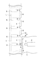
- six moving blocks 3A to 3F are fixed to the movable body 41, and each is assembled to one of the two guide tracks 2A and 2B.
- two moving blocks 3A and 3B are assembled to the guide track 2A
- four moving blocks 3C to 3F are assembled to the guide track 2B.
- the arrangement interval of the two moving blocks 3A and 3B assembled to the guide track 2A is different from the arrangement interval of the four moving blocks 3C to 3F assembled to the guide track 2B.
- moving blocks 3A and 3B are provided at positions displaced with respect to any of the moving blocks 3C to 3F on the guide track 2B side. That is, with respect to the longitudinal direction of the guide tracks 2A and 2B, the moving blocks 3A and 3 on the guide track 2A side and the moving blocks 3C to 3F on the guide track 2B side are fixed to the movable body 41 with their phases shifted. More specifically, in the example shown in FIG.
- the moving block 3A on the guide track 2A side and the moving blocks 3C and 3D on the guide track 2B side are arranged on the movable body 41 so as to form a triangle
- the guide track The moving block 3B on the 2A side and the moving blocks 3E and 3F on the guide track 2B side are arranged on the movable body 41 so as to form a triangle.
- the length of each track rail 21 constituting each guide track 2A, 2B is set longer than the distance between the moving block 3C and the moving block 3D.
- the moving block 3F on the guide track 2B passes through the joint clearance L of the guide track 2B
- the moving block 3B on the guide track 2A enters the joint clearance L of the guide track 2A.
- the moving block 3B on the guide track 2A passes through the joint gap L of the guide track 2A
- the moving block 3F on the guide track 2B side has already passed through the joint gap L, and the moving block 3E is connected to the joint portion. It has not entered the gap L. That is, even though one of the six moving blocks fixed to the movable body is present on the joint gap L of the guide tracks 2A and 2B, the other five blocks enter the joint gap L. It is in the state assembled
- the movable body 41 passes through the joint gap L, even if one moving block 3 falls into a state in which a load cannot be applied in the joint gap L, the remaining moving blocks 3 are not connected to the joint. Since it is assembled to the track rail 21 without being positioned in the gap L, it is possible to reliably load the load acting on the movable body 41 by these moving blocks 3. Thereby, it is possible to move the movable body 41 in a stable state over the entire length of the long guide tracks 2A and 2B.
- the fixed number of the moving blocks 3 with respect to the movable body 41 is not limited to six, and it is sufficient that two or more moving blocks 3 are assembled to each of the guide tracks 2A and 2B.
- FIG. 6 shows an example in which four moving blocks 3A to 3D are fixed to the movable body 41. As shown in FIG. Thus, even when four moving blocks 3A to 3D are used, the arrangement interval between the two moving blocks 3A and 3B assembled on the guide track 2A is the same as that of the two moving blocks 3A and 3B mounted on the guide track 2B. This is different from the arrangement interval of the blocks 3C and 3D. That is, the moving blocks 3A and 3B on the guide track 2A side are fixed to the movable body 41 with a phase shifted from the moving blocks 3C and 3D on the guide track 2B side.
- the moving block 3D enters the joint gap L of the guide track 2A
- the other moving blocks 3A to 3C are assembled to the track rail 21 without overlapping the joint gap. Accordingly, a load acting on the movable body 41 can be applied by the three moving blocks 3A to 3C, and the movable body 41 can be stably moved over the entire length of the guide tracks 2A and 2B.
- the arrangement interval of the plurality of moving blocks 3 assembled on one guide track 2A is different from the arrangement interval of the plurality of moving blocks 3 assembled on the other guide track 2B. This prevents the plurality of moving blocks 3 from being simultaneously positioned in the joint gap L. However, by intentionally shifting the position of the joint gap L in the guide track 2A and the position of the joint gap in the guide track 2B, it is possible to avoid the plurality of moving blocks 3 from being positioned in the joint gap L at the same time. Good.
- ball guide surfaces are provided at both ends in the longitudinal direction of the rolling surface 24 of the track rail 21.
- This ball guiding surface is formed by applying a crowning process to the end of the rolling surface 24.
- the distance between the moving block 3 and the rolling surface 24 is the track.
- the ball guide surface is provided to facilitate the passage of the moving block 3 in the joint gap L, and the moving block 3 passes through the joint gap L due to the presence of the ball guide surface.
- the load applied to the ball 31 existing between the moving block 3 and the track rail 21 is gradually reduced and gradually increased again.
- the formation of the ball guide surface with respect to the rolling surface 24 of the track rail 21 is arbitrary, and the moving block 3 can pass through the joint gap L even when the ball guide surface is not formed.
- the moving block in the present invention is not limited to that shown in FIG. 4, that is, the type in which the ball has an infinite circulation path and the ball rolls on the rolling surface 24 of the track rail 21.
- a moving block having a low frictional sliding contact member slides on the track rail, or a moving block having a shaft-supported wheel that travels on the track rail while rotating the wheel. It may be.
- the movable body 41 can freely move to any position on the guide tracks 2A and 2B. However, in the actual use situation, the movable body 41 is moved with respect to the guide tracks 2A and 2B. It is considered that the movable body 41 is often used while being fixed at a specific position on the guide tracks 2A and 2B.
- the movable body 41 can be provided with a position fixing member. This position fixing member restrains the movement of the movable body 41 using fixed holes 26 provided in the track rail 21 at regular intervals, and the operator can move the movable body 41 to a specific position on the guide tracks 2A and 2B. After the body 41 is moved, the movable body 41 can be fixed at an arbitrary position corresponding to the fixing hole 26 by operating the position fixing member.
- FIG. 7 and 8 show an embodiment of the position fixing member, and are side cross-sectional views observed from the longitudinal direction of the track member 2.
- FIG. FIG. 7 shows an initial state of the position fixing member
- FIG. 8 shows an operating state of the position fixing member.
- the position fixing member 7 includes a locking pin 72 that is inserted into and removed from the fixing hole 26 provided in the track rail 21, a setting pin 71 that switches the position fixing member 7 to an initial state or an operating state, and the setting pin 71.
- the driven plate 73 is configured to transmit the above movement to the locking pin 72, and the setting pin 71, the locking pin 72, and the driven plate 73 are housed and the housing 74 is fixed to the movable body 41.
- the setting pin 71 includes a shank portion 71a that is provided orthogonal to the locking pin 72 and protrudes from the housing 74, and a cam portion 71b that is rotatably provided at one end of the shank portion 71a.
- the shank portion 71a protrudes from the movable body 41 to the opposite side to the ceiling panel 101, and a female screw is provided at the tip of the shank portion 71a so that another member for pushing and pulling the shank portion 71a in the axial direction can be connected.
- the setting pin 71 is held by the housing 74 so as to be movable in the axial direction of the shank portion 71a. Therefore, the tip of the setting pin 71 protrudes into the service unit 42 shown in FIGS. 2 and 3, for example, and the setting pin can be operated from the service unit 42 side.
- the follower plate 73 is a member that converts the movement of the setting pin in the axial direction into a movement in a direction orthogonal thereto, and an inclined portion 73a with which the outer peripheral surface of the cam portion 71b of the setting pin 71 is in sliding contact
- the cam portion 71b includes a holding portion 73b that is formed in a concave shape with substantially the same radius of curvature as the outer peripheral surface of the cam portion 71b and continues from the inclined portion 73a.
- the locking pin 72 is a cylindrical member, and its axis is substantially coincident with the fixed hole 26 of the track rail 21 and is held by the housing 74 so as to be movable in the axial direction.
- the locking pin 72 is always urged away from the track rail 21 by a coil spring 74 a provided in the housing 74.
- the rear end of the locking pin 72 is fixed to the driven plate 73, and the locking pin 72 enters and exits the fixed hole 26 of the track rail 21 according to the movement of the driven plate 73.
- the locking pin 72 is pulled out of the fixing hole 26 of the track rail 21 by the action of the coil spring 74a.
- the position fixing member 7 does not function at all. 41 can move freely along the longitudinal direction of the track rail.
- the cam portion 71 b of the setting pin 71 is in contact with the inclined portion 73 a of the driven plate 73.
- the holding portion 73b of the driven plate 73 formed in a concave shape is pressed against the cam portion 71b of the setting pin 71 by the elastic force of the compressed and compressed coil spring 74a. Unless the part 71b is intentionally pulled back, the cam part 71b does not detach from the holding part 73b of the driven plate 73, and the locking pin 72 does not come out of the fixing hole 26 of the track rail 21.
- the locking pin 72 is inserted into the fixing hole 26 of the track rail 21.
- the movable body 41 is inserted and fixed at the position. Further, when the setting pin 71 is pulled back, the cam portion 71b is detached from the holding portion 73b of the driven plate 73, so that the locking pin 72 is pulled back and comes out of the fixed hole 26 of the track rail, and again the movable body 41. Can be moved along the guide tracks 2A and 2B.
- FIG. 9 shows an example of the position detection member.
- the position detecting member 8 includes a reference plate 81 fixed to the ceiling plate 101 together with the track rails 21, and an elastic plate 82 fixed to the movable body 41 and moved along the guide tracks 2A and 2B together with the movable body 41. It consists of and.
- the reference plate 81 is a long plate-like member provided along the longitudinal direction of the track rail 21, and a plurality of locking grooves 83 are formed at equal intervals along the longitudinal direction.
- the formation interval of the locking grooves 83 is the same as the formation interval of the fixing holes 26 of the track rail 21.
- the elastic plate 82 is formed by bending a thin plate and has a locking projection 84 that fits into the locking groove 83 of the reference plate 81.
- the elastic plate 82 is fixed to the movable body 41, so that the tip of the locking projection 84 enters the locking groove 83 of the reference plate 81, and the locking projection 84 is fixed to the position fixing member 7.
- the fixing position is adjusted so as to overlap with the locking pin 72. Since the elastic plate 82 is formed by bending a thin plate, it is easily elastically deformed.
- the elastic plate 82 is moved.
- the locking projection 84 comes out of the locking groove 83, rides on the peak portion 85 of the reference plate 81 existing between the locking grooves 83, and enters the next locking groove 83 again.
- the locking protrusion 84 of the elastic plate 82 moves along the reference plate 81 and moves into the locking groove 83 of the reference plate 81.
- the entrance and exit will be repeated.
- the operator who moves the movable body 41 can easily realize whether or not the locking projection 84 is fitted in the locking groove 83.
- the locking pin 72 of the position fixing member 7 faces the fixing hole 26 of the track rail 21, so that the operator can fix the position. By operating the setting pin 71 of the member 7, the locking pin 72 can be easily inserted into the fixing hole 26 of the track rail 21.
- the operator easily recognizes the position of the fixing hole 26 of the track rail 21 when moving the movable body 41 along the guide tracks 2A and 2B and fixing the movable body 41 at a predetermined position.
- the movable body 41 can be easily fixed using the position fixing member 7 described above.
Landscapes
- Engineering & Computer Science (AREA)
- General Engineering & Computer Science (AREA)
- Mechanical Engineering (AREA)
- Aviation & Aerospace Engineering (AREA)
- Bearings For Parts Moving Linearly (AREA)
- Transmission Devices (AREA)
Description
Claims (3)
- 固定部(101)に対して互いに平行に敷設される一対の案内軌道(2)と、各案内軌道(2)に対して少なくとも2基以上組み付けられると共に当該案内軌道(2)に沿って移動自在な複数の移動ブロック(3)と、これら移動ブロック(3)に固定されて前記固定部(101)上を移動自在な可動体(41)と、を備え、
各案内軌道(2)は長手方向に沿って案内面(25)が形成された複数の軌道レール(21)をその端部同士を接続して直列に配置して設けられる一方、前記移動ブロック(3)は直列に配置された複数の軌道レール(21)の継ぎ部隙間(L)を通過しながら前記案内面(25)を走行する接触子(31)を有し、
前記一対の案内軌道(2)に含まれる複数の継ぎ部隙間(L)に関し、いずれか1カ所の継ぎ部隙間上に前記移動ブロック(3)が位置している際に、他の継ぎ部隙間上には前記移動ブロック(3)が位置していないことを特徴とする移動ユニット。 - 各軌道レール同士の継ぎ目隙間(L)には前記接触子(31)の直径よりも大きな隙間が形成されていることを特徴とする請求項1記載の移動ユニット。
- 各軌道レール(21)には長手方向に沿って所定の間隔で複数の固定孔(26)が配列される一方、
前記可動体(41)には前記案内軌道(2)に対する前記可動体(41)の移動を拘束する位置固定部材(7)が設けられ、かかる位置固定部材(7)は前記軌道レール(21)のいずれかの固定孔(26)に抜き差し自在な係止ピン(72)を有していることを特徴とする請求項1又は2記載の移動ユニット。
Priority Applications (6)
| Application Number | Priority Date | Filing Date | Title |
|---|---|---|---|
| EP13816948.7A EP2873882B1 (en) | 2012-07-13 | 2013-07-04 | Movement unit |
| CA2878232A CA2878232C (en) | 2012-07-13 | 2013-07-04 | Movement unit |
| ES13816948.7T ES2613883T3 (es) | 2012-07-13 | 2013-07-04 | Unidad de movimiento |
| CN201380029281.7A CN104334897B (zh) | 2012-07-13 | 2013-07-04 | 移动单元 |
| US14/405,358 US9279539B2 (en) | 2012-07-13 | 2013-07-04 | Movement unit |
| BR112015000357-5A BR112015000357B1 (pt) | 2012-07-13 | 2013-07-04 | Unidade de movimento |
Applications Claiming Priority (2)
| Application Number | Priority Date | Filing Date | Title |
|---|---|---|---|
| JP2012157329 | 2012-07-13 | ||
| JP2012-157329 | 2012-07-13 |
Publications (1)
| Publication Number | Publication Date |
|---|---|
| WO2014010507A1 true WO2014010507A1 (ja) | 2014-01-16 |
Family
ID=49915964
Family Applications (1)
| Application Number | Title | Priority Date | Filing Date |
|---|---|---|---|
| PCT/JP2013/068387 Ceased WO2014010507A1 (ja) | 2012-07-13 | 2013-07-04 | 移動ユニット |
Country Status (9)
| Country | Link |
|---|---|
| US (1) | US9279539B2 (ja) |
| EP (1) | EP2873882B1 (ja) |
| JP (1) | JP5995795B2 (ja) |
| CN (1) | CN104334897B (ja) |
| BR (1) | BR112015000357B1 (ja) |
| CA (1) | CA2878232C (ja) |
| ES (1) | ES2613883T3 (ja) |
| TW (1) | TWI572789B (ja) |
| WO (1) | WO2014010507A1 (ja) |
Families Citing this family (9)
| Publication number | Priority date | Publication date | Assignee | Title |
|---|---|---|---|---|
| KR101259822B1 (ko) * | 2010-11-12 | 2013-04-30 | 삼성중공업 주식회사 | 선체 블록 내부 작업용 이동 장치 및 선체 블록의 내부 작업 방법 |
| DE102014115747A1 (de) * | 2014-10-29 | 2016-05-04 | Airbus Operations Gmbh | Modulares Monument zum Befördern eines Transportgutes in einem Fahrzeug |
| USD835492S1 (en) * | 2015-02-24 | 2018-12-11 | Thk Co., Ltd. | Slide rail |
| US10239617B2 (en) | 2015-09-11 | 2019-03-26 | The Boeing Company | Oxygen box for a limited maintenance access area above a ceiling panel of an aircraft cabin |
| US10589863B2 (en) | 2017-05-08 | 2020-03-17 | The Boeing Company | Apparatus and methods to attach an object to an overhead section of a cabin of an aircraft |
| US20200164986A1 (en) | 2018-11-27 | 2020-05-28 | The Boeing Company | Suspended serving system and methods |
| JP7219240B2 (ja) * | 2020-02-28 | 2023-02-07 | 日本トムソン株式会社 | 直動案内ユニット |
| DE102020133905A1 (de) * | 2020-12-17 | 2022-06-23 | Airbus Operations Gmbh | Positionsdetektor, Passagierversorgungskanal und Fahrzeugbereich zur Lagebestimmung einer Passagierversorgungseinheit |
| JP1696218S (ja) * | 2021-03-29 | 2021-10-04 |
Citations (5)
| Publication number | Priority date | Publication date | Assignee | Title |
|---|---|---|---|---|
| JPS6256660A (ja) * | 1985-09-04 | 1987-03-12 | Nippon Seiko Kk | リニアガイド装置用軌道レ−ルのボ−ル転動溝加工方法 |
| JPH0293117A (ja) * | 1988-09-30 | 1990-04-03 | Copal Electron Co Ltd | 直線運動機構 |
| JPH05133416A (ja) * | 1991-11-07 | 1993-05-28 | Nippon Thompson Co Ltd | 防振性を有する直動案内ユニツト及びその製造方法 |
| JPH07269569A (ja) * | 1994-03-27 | 1995-10-17 | Nobuyuki Tsuboi | 運動装置のガイドレール |
| WO2005031082A1 (ja) | 2003-09-26 | 2005-04-07 | Thk Co., Ltd. | 壁掛け装置 |
Family Cites Families (10)
| Publication number | Priority date | Publication date | Assignee | Title |
|---|---|---|---|---|
| DE29503473U1 (de) * | 1995-03-02 | 1996-07-18 | Karmann-Rheine GmbH & Co KG, 48432 Rheine | Klapptisch für Fahrzeuge zur Personenbeförderung |
| JPH1130233A (ja) * | 1997-07-09 | 1999-02-02 | Thk Kk | 直線運動案内装置 |
| US6254047B1 (en) * | 1999-05-27 | 2001-07-03 | The United States Of America As Represented By The Secretary Department Of The Army | Equipment roller/slide support |
| DE20013363U1 (de) * | 2000-08-03 | 2000-12-21 | Igus Spritzgußteile für die Industrie GmbH, 51147 Köln | Loslager |
| JP2005016719A (ja) * | 2003-05-30 | 2005-01-20 | Thk Co Ltd | 制振材料及びこの制振材料を組み込んだ運動案内装置 |
| JP4231364B2 (ja) * | 2003-07-28 | 2009-02-25 | 東京エレクトロン株式会社 | ベローズ支持構造及び可動ステージ |
| CN100535463C (zh) * | 2004-09-08 | 2009-09-02 | Thk株式会社 | 线性导向装置及其轨道的制造方法 |
| US20090230265A1 (en) * | 2008-03-17 | 2009-09-17 | Michael Newman | Mounting System for Photovoltaic Panels |
| US8182183B2 (en) * | 2008-11-18 | 2012-05-22 | L-3 Communications Integrated Systems L.P. | Systems and methods for securing components |
| WO2013171925A1 (ja) * | 2012-05-15 | 2013-11-21 | 株式会社みづほ合成工業所 | 機器固定構造 |
-
2013
- 2013-07-04 ES ES13816948.7T patent/ES2613883T3/es active Active
- 2013-07-04 EP EP13816948.7A patent/EP2873882B1/en active Active
- 2013-07-04 US US14/405,358 patent/US9279539B2/en active Active
- 2013-07-04 CN CN201380029281.7A patent/CN104334897B/zh active Active
- 2013-07-04 BR BR112015000357-5A patent/BR112015000357B1/pt active IP Right Grant
- 2013-07-04 WO PCT/JP2013/068387 patent/WO2014010507A1/ja not_active Ceased
- 2013-07-04 JP JP2013140367A patent/JP5995795B2/ja active Active
- 2013-07-04 CA CA2878232A patent/CA2878232C/en active Active
- 2013-07-11 TW TW102124913A patent/TWI572789B/zh active
Patent Citations (5)
| Publication number | Priority date | Publication date | Assignee | Title |
|---|---|---|---|---|
| JPS6256660A (ja) * | 1985-09-04 | 1987-03-12 | Nippon Seiko Kk | リニアガイド装置用軌道レ−ルのボ−ル転動溝加工方法 |
| JPH0293117A (ja) * | 1988-09-30 | 1990-04-03 | Copal Electron Co Ltd | 直線運動機構 |
| JPH05133416A (ja) * | 1991-11-07 | 1993-05-28 | Nippon Thompson Co Ltd | 防振性を有する直動案内ユニツト及びその製造方法 |
| JPH07269569A (ja) * | 1994-03-27 | 1995-10-17 | Nobuyuki Tsuboi | 運動装置のガイドレール |
| WO2005031082A1 (ja) | 2003-09-26 | 2005-04-07 | Thk Co., Ltd. | 壁掛け装置 |
Also Published As
| Publication number | Publication date |
|---|---|
| US20150122963A1 (en) | 2015-05-07 |
| EP2873882A1 (en) | 2015-05-20 |
| BR112015000357A2 (pt) | 2017-06-27 |
| TW201420904A (zh) | 2014-06-01 |
| US9279539B2 (en) | 2016-03-08 |
| ES2613883T3 (es) | 2017-05-26 |
| JP2014031885A (ja) | 2014-02-20 |
| CN104334897B (zh) | 2017-06-16 |
| CA2878232C (en) | 2019-07-16 |
| EP2873882B1 (en) | 2016-11-16 |
| BR112015000357B1 (pt) | 2021-07-13 |
| CA2878232A1 (en) | 2014-01-16 |
| TWI572789B (zh) | 2017-03-01 |
| EP2873882A4 (en) | 2015-08-19 |
| JP5995795B2 (ja) | 2016-09-21 |
| CN104334897A (zh) | 2015-02-04 |
Similar Documents
| Publication | Publication Date | Title |
|---|---|---|
| JP5995795B2 (ja) | 移動ユニット | |
| JP5723356B2 (ja) | 運動案内装置 | |
| JP2018042993A (ja) | スライドレールアセンブリ | |
| CN105026777B (zh) | 支撑引导装置 | |
| US20190345963A1 (en) | Device-securing apparatus | |
| JP5808375B2 (ja) | 移動ユニット | |
| CN104321631A (zh) | 发动机测试装置 | |
| TWI709697B (zh) | 滾動引導裝置 | |
| CN106880197B (zh) | 滑轨总成 | |
| KR20110126337A (ko) | 미끄럼방지용 롤러가이드 | |
| US10082174B2 (en) | Movement guide device | |
| JP2014065547A (ja) | クリック機構及びこれを備えた運動案内装置 | |
| WO2019098086A1 (ja) | 運動案内装置のレールカバー | |
| WO2019098090A1 (ja) | 運動案内装置のロック機構及びこれを用いた転がり案内装置 | |
| JP2010078037A (ja) | 運動案内装置及びこれに用いられるリテーナ |
Legal Events
| Date | Code | Title | Description |
|---|---|---|---|
| 121 | Ep: the epo has been informed by wipo that ep was designated in this application |
Ref document number: 13816948 Country of ref document: EP Kind code of ref document: A1 |
|
| REEP | Request for entry into the european phase |
Ref document number: 2013816948 Country of ref document: EP |
|
| WWE | Wipo information: entry into national phase |
Ref document number: 2013816948 Country of ref document: EP |
|
| WWE | Wipo information: entry into national phase |
Ref document number: 14405358 Country of ref document: US |
|
| ENP | Entry into the national phase |
Ref document number: 2878232 Country of ref document: CA |
|
| NENP | Non-entry into the national phase |
Ref country code: DE |
|
| REG | Reference to national code |
Ref country code: BR Ref legal event code: B01A Ref document number: 112015000357 Country of ref document: BR |
|
| ENP | Entry into the national phase |
Ref document number: 112015000357 Country of ref document: BR Kind code of ref document: A2 Effective date: 20150108 |