WO2014065279A1 - 摺動部材及び摺動部材の製造方法 - Google Patents
摺動部材及び摺動部材の製造方法 Download PDFInfo
- Publication number
- WO2014065279A1 WO2014065279A1 PCT/JP2013/078581 JP2013078581W WO2014065279A1 WO 2014065279 A1 WO2014065279 A1 WO 2014065279A1 JP 2013078581 W JP2013078581 W JP 2013078581W WO 2014065279 A1 WO2014065279 A1 WO 2014065279A1
- Authority
- WO
- WIPO (PCT)
- Prior art keywords
- sintered body
- body layer
- sliding member
- metal powder
- sliding
- Prior art date
- Legal status (The legal status is an assumption and is not a legal conclusion. Google has not performed a legal analysis and makes no representation as to the accuracy of the status listed.)
- Ceased
Links
Images




Classifications
-
- B—PERFORMING OPERATIONS; TRANSPORTING
- B22—CASTING; POWDER METALLURGY
- B22F—WORKING METALLIC POWDER; MANUFACTURE OF ARTICLES FROM METALLIC POWDER; MAKING METALLIC POWDER; APPARATUS OR DEVICES SPECIALLY ADAPTED FOR METALLIC POWDER
- B22F3/00—Manufacture of workpieces or articles from metallic powder characterised by the manner of compacting or sintering; Apparatus specially adapted therefor ; Presses and furnaces
- B22F3/24—After-treatment of workpieces or articles
-
- B—PERFORMING OPERATIONS; TRANSPORTING
- B22—CASTING; POWDER METALLURGY
- B22F—WORKING METALLIC POWDER; MANUFACTURE OF ARTICLES FROM METALLIC POWDER; MAKING METALLIC POWDER; APPARATUS OR DEVICES SPECIALLY ADAPTED FOR METALLIC POWDER
- B22F3/00—Manufacture of workpieces or articles from metallic powder characterised by the manner of compacting or sintering; Apparatus specially adapted therefor ; Presses and furnaces
- B22F3/10—Sintering only
-
- B—PERFORMING OPERATIONS; TRANSPORTING
- B22—CASTING; POWDER METALLURGY
- B22F—WORKING METALLIC POWDER; MANUFACTURE OF ARTICLES FROM METALLIC POWDER; MAKING METALLIC POWDER; APPARATUS OR DEVICES SPECIALLY ADAPTED FOR METALLIC POWDER
- B22F3/00—Manufacture of workpieces or articles from metallic powder characterised by the manner of compacting or sintering; Apparatus specially adapted therefor ; Presses and furnaces
- B22F3/12—Both compacting and sintering
- B22F3/16—Both compacting and sintering in successive or repeated steps
-
- B—PERFORMING OPERATIONS; TRANSPORTING
- B22—CASTING; POWDER METALLURGY
- B22F—WORKING METALLIC POWDER; MANUFACTURE OF ARTICLES FROM METALLIC POWDER; MAKING METALLIC POWDER; APPARATUS OR DEVICES SPECIALLY ADAPTED FOR METALLIC POWDER
- B22F5/00—Manufacture of workpieces or articles from metallic powder characterised by the special shape of the product
-
- B—PERFORMING OPERATIONS; TRANSPORTING
- B22—CASTING; POWDER METALLURGY
- B22F—WORKING METALLIC POWDER; MANUFACTURE OF ARTICLES FROM METALLIC POWDER; MAKING METALLIC POWDER; APPARATUS OR DEVICES SPECIALLY ADAPTED FOR METALLIC POWDER
- B22F7/00—Manufacture of composite layers, workpieces, or articles, comprising metallic powder, by sintering the powder, with or without compacting wherein at least one part is obtained by sintering or compression
- B22F7/008—Manufacture of composite layers, workpieces, or articles, comprising metallic powder, by sintering the powder, with or without compacting wherein at least one part is obtained by sintering or compression characterised by the composition
-
- B—PERFORMING OPERATIONS; TRANSPORTING
- B22—CASTING; POWDER METALLURGY
- B22F—WORKING METALLIC POWDER; MANUFACTURE OF ARTICLES FROM METALLIC POWDER; MAKING METALLIC POWDER; APPARATUS OR DEVICES SPECIALLY ADAPTED FOR METALLIC POWDER
- B22F7/00—Manufacture of composite layers, workpieces, or articles, comprising metallic powder, by sintering the powder, with or without compacting wherein at least one part is obtained by sintering or compression
- B22F7/02—Manufacture of composite layers, workpieces, or articles, comprising metallic powder, by sintering the powder, with or without compacting wherein at least one part is obtained by sintering or compression of composite layers
-
- B—PERFORMING OPERATIONS; TRANSPORTING
- B22—CASTING; POWDER METALLURGY
- B22F—WORKING METALLIC POWDER; MANUFACTURE OF ARTICLES FROM METALLIC POWDER; MAKING METALLIC POWDER; APPARATUS OR DEVICES SPECIALLY ADAPTED FOR METALLIC POWDER
- B22F7/00—Manufacture of composite layers, workpieces, or articles, comprising metallic powder, by sintering the powder, with or without compacting wherein at least one part is obtained by sintering or compression
- B22F7/06—Manufacture of composite layers, workpieces, or articles, comprising metallic powder, by sintering the powder, with or without compacting wherein at least one part is obtained by sintering or compression of composite workpieces or articles from parts, e.g. to form tipped tools
-
- B—PERFORMING OPERATIONS; TRANSPORTING
- B32—LAYERED PRODUCTS
- B32B—LAYERED PRODUCTS, i.e. PRODUCTS BUILT-UP OF STRATA OF FLAT OR NON-FLAT, e.g. CELLULAR OR HONEYCOMB, FORM
- B32B15/00—Layered products comprising a layer of metal
- B32B15/01—Layered products comprising a layer of metal all layers being exclusively metallic
-
- B—PERFORMING OPERATIONS; TRANSPORTING
- B32—LAYERED PRODUCTS
- B32B—LAYERED PRODUCTS, i.e. PRODUCTS BUILT-UP OF STRATA OF FLAT OR NON-FLAT, e.g. CELLULAR OR HONEYCOMB, FORM
- B32B15/00—Layered products comprising a layer of metal
- B32B15/01—Layered products comprising a layer of metal all layers being exclusively metallic
- B32B15/013—Layered products comprising a layer of metal all layers being exclusively metallic one layer being formed of an iron alloy or steel, another layer being formed of a metal other than iron or aluminium
- B32B15/015—Layered products comprising a layer of metal all layers being exclusively metallic one layer being formed of an iron alloy or steel, another layer being formed of a metal other than iron or aluminium the said other metal being copper or nickel or an alloy thereof
-
- C—CHEMISTRY; METALLURGY
- C22—METALLURGY; FERROUS OR NON-FERROUS ALLOYS; TREATMENT OF ALLOYS OR NON-FERROUS METALS
- C22C—ALLOYS
- C22C9/00—Alloys based on copper
- C22C9/02—Alloys based on copper with tin as the next major constituent
-
- F—MECHANICAL ENGINEERING; LIGHTING; HEATING; WEAPONS; BLASTING
- F16—ENGINEERING ELEMENTS AND UNITS; GENERAL MEASURES FOR PRODUCING AND MAINTAINING EFFECTIVE FUNCTIONING OF MACHINES OR INSTALLATIONS; THERMAL INSULATION IN GENERAL
- F16C—SHAFTS; FLEXIBLE SHAFTS; ELEMENTS OR CRANKSHAFT MECHANISMS; ROTARY BODIES OTHER THAN GEARING ELEMENTS; BEARINGS
- F16C33/00—Parts of bearings; Special methods for making bearings or parts thereof
- F16C33/02—Parts of sliding-contact bearings
- F16C33/04—Brasses; Bushes; Linings
- F16C33/06—Sliding surface mainly made of metal
- F16C33/14—Special methods of manufacture; Running-in
-
- F—MECHANICAL ENGINEERING; LIGHTING; HEATING; WEAPONS; BLASTING
- F16—ENGINEERING ELEMENTS AND UNITS; GENERAL MEASURES FOR PRODUCING AND MAINTAINING EFFECTIVE FUNCTIONING OF MACHINES OR INSTALLATIONS; THERMAL INSULATION IN GENERAL
- F16C—SHAFTS; FLEXIBLE SHAFTS; ELEMENTS OR CRANKSHAFT MECHANISMS; ROTARY BODIES OTHER THAN GEARING ELEMENTS; BEARINGS
- F16C33/00—Parts of bearings; Special methods for making bearings or parts thereof
- F16C33/02—Parts of sliding-contact bearings
- F16C33/04—Brasses; Bushes; Linings
- F16C33/06—Sliding surface mainly made of metal
- F16C33/14—Special methods of manufacture; Running-in
- F16C33/145—Special methods of manufacture; Running-in of sintered porous bearings
-
- B—PERFORMING OPERATIONS; TRANSPORTING
- B22—CASTING; POWDER METALLURGY
- B22F—WORKING METALLIC POWDER; MANUFACTURE OF ARTICLES FROM METALLIC POWDER; MAKING METALLIC POWDER; APPARATUS OR DEVICES SPECIALLY ADAPTED FOR METALLIC POWDER
- B22F2207/00—Aspects of the compositions, gradients
- B22F2207/11—Gradients other than composition gradients, e.g. size gradients
- B22F2207/17—Gradients other than composition gradients, e.g. size gradients density or porosity gradients
-
- B—PERFORMING OPERATIONS; TRANSPORTING
- B22—CASTING; POWDER METALLURGY
- B22F—WORKING METALLIC POWDER; MANUFACTURE OF ARTICLES FROM METALLIC POWDER; MAKING METALLIC POWDER; APPARATUS OR DEVICES SPECIALLY ADAPTED FOR METALLIC POWDER
- B22F2998/00—Supplementary information concerning processes or compositions relating to powder metallurgy
- B22F2998/10—Processes characterised by the sequence of their steps
-
- F—MECHANICAL ENGINEERING; LIGHTING; HEATING; WEAPONS; BLASTING
- F16—ENGINEERING ELEMENTS AND UNITS; GENERAL MEASURES FOR PRODUCING AND MAINTAINING EFFECTIVE FUNCTIONING OF MACHINES OR INSTALLATIONS; THERMAL INSULATION IN GENERAL
- F16C—SHAFTS; FLEXIBLE SHAFTS; ELEMENTS OR CRANKSHAFT MECHANISMS; ROTARY BODIES OTHER THAN GEARING ELEMENTS; BEARINGS
- F16C2202/00—Solid materials defined by their properties
- F16C2202/02—Mechanical properties
- F16C2202/04—Hardness
-
- F—MECHANICAL ENGINEERING; LIGHTING; HEATING; WEAPONS; BLASTING
- F16—ENGINEERING ELEMENTS AND UNITS; GENERAL MEASURES FOR PRODUCING AND MAINTAINING EFFECTIVE FUNCTIONING OF MACHINES OR INSTALLATIONS; THERMAL INSULATION IN GENERAL
- F16C—SHAFTS; FLEXIBLE SHAFTS; ELEMENTS OR CRANKSHAFT MECHANISMS; ROTARY BODIES OTHER THAN GEARING ELEMENTS; BEARINGS
- F16C33/00—Parts of bearings; Special methods for making bearings or parts thereof
- F16C33/02—Parts of sliding-contact bearings
- F16C33/04—Brasses; Bushes; Linings
- F16C33/06—Sliding surface mainly made of metal
- F16C33/12—Structural composition; Use of special materials or surface treatments, e.g. for rust-proofing
- F16C33/121—Use of special materials
-
- Y—GENERAL TAGGING OF NEW TECHNOLOGICAL DEVELOPMENTS; GENERAL TAGGING OF CROSS-SECTIONAL TECHNOLOGIES SPANNING OVER SEVERAL SECTIONS OF THE IPC; TECHNICAL SUBJECTS COVERED BY FORMER USPC CROSS-REFERENCE ART COLLECTIONS [XRACs] AND DIGESTS
- Y10—TECHNICAL SUBJECTS COVERED BY FORMER USPC
- Y10T—TECHNICAL SUBJECTS COVERED BY FORMER US CLASSIFICATION
- Y10T428/00—Stock material or miscellaneous articles
- Y10T428/12—All metal or with adjacent metals
- Y10T428/12014—All metal or with adjacent metals having metal particles
- Y10T428/12028—Composite; i.e., plural, adjacent, spatially distinct metal components [e.g., layers, etc.]
Definitions
- the present invention relates to a sliding member that slidably supports an object to be slid and a manufacturing method of the sliding member.
- an oil sump is formed on the sliding surface and can have a low coefficient of friction, and good sliding characteristics can be obtained. Moreover, it can have a favorable sliding characteristic also if a sliding layer is comprised with a copper-type alloy.
- the conventional sliding member in which the sliding layer is made of a copper-based alloy has insufficient hardness, and the desired sliding characteristics cannot be maintained under an environment where a high load is applied, such as a hydraulic device.
- the present invention relates to a sliding member having a hardness suitable for an environment in which a high load is applied and having excellent wear resistance, and a sliding member having a hardness suitable for an environment in which a high load is applied and having excellent wear resistance. It is an object of the present invention to provide a method for manufacturing a sliding member that suppresses generation of offcuts that do not become products as much as possible.
- the present inventors have performed a blast treatment on the sintered body of the copper-based alloy so that the sintered body is densified and the hardness is improved, and the surface of the sintered body has an oil suitable for wear resistance and the like. It has been found that irregularities are formed with a surface roughness capable of forming a pool.
- the present invention provides a first sintered body layer obtained by molding and sintering a first metal powder, and a second composition having a composition different from that of the first metal powder on one surface of the first sintered body layer.
- the first metal powder is preferably composed of an iron-based material
- the second metal powder is preferably composed of a copper-based material
- the second sintered body layer is densified so that the hardness of at least the sliding surface as one surface is Hv (Vickers hardness) 150 or more and Hv 250 or less, more preferably Hv 170 or more and Hv 220 or less. It is preferred that
- the present invention also includes a step of molding the first metal powder, sintering the molded first metal powder to form the first sintered body layer, and at least one of the first sintered body layers.
- the second metal powder dispersed on one surface of the layer is hardened, the shape matching the shape of the first sintered body layer is maintained, the second metal powder is bonded
- a blasting step of densifying the second sintered body layer by applying a pressure that crushes the voids in the treatment to reduce the voids. It is preferable to include the secondary sintering process
- the second sintered body layer which is the sliding layer
- the second sintered body layer can have high hardness characteristics suitable for an environment where a high load is applied, and the second sintered body layer
- An oil reservoir can be formed on the surface, and low friction and wear resistance can be ensured by interposing an oil film.
- the manufacturing method of the sliding member of this invention since the 1st sintered body layer is shape
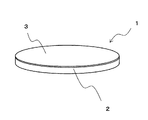
- FIG. 1 is a perspective view showing an outline of a sliding member of the present embodiment
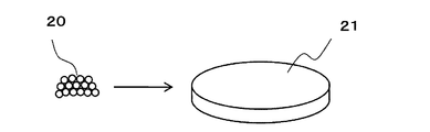
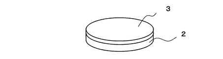
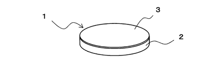
- FIGS. 2A, 2B, 2C, 2D, and 2E show an example of a manufacturing method of the sliding member of the present embodiment. It is explanatory drawing.
- the sliding member 1 of the present embodiment has a first sintered body layer 2 in which metal powder of a predetermined composition is hardened by sintering, and a surface that is one surface of the first sintered body layer 2.
- the first sintered body layer 2 is provided with a second sintered body layer 3 in which a metal powder having a composition different from that of the metal powder constituting the first sintered body layer 2 is sintered, and has a flat plate Composed.
- the sliding member 1 is a striking process called a blasting process in which a metal powder having a predetermined material and particle diameter collides against the surface of the second sintered body layer 3, and the second sintered body layer 3 is densified.
- the sliding member 1 includes a back metal that supports the second sintered body layer 3 in which the densified second sintered body layer 3 serves as a sliding layer and the first sintered body layer 2 is a sliding layer. It becomes.
- the first sintered body layer 2 is obtained by sintering a powder of iron (Fe) as a metal powder having a predetermined composition or a powder of an alloy containing iron as a main component and an additive such as copper (Cu). Consolidated and composed.
- the second sintered body layer 3 is configured by sintering a powder of a copper-tin (Cu-Sn) alloy as a metal powder having a predetermined composition for the purpose of improving slidability. .
- the sliding member When the sliding member is formed only by the configuration corresponding to the first sintered body layer 2, seizure may occur when the sliding member is iron, and the sliding property is poor. Therefore, in the sliding member 1, the sliding property is improved by providing a sliding layer of a Cu-based alloy on the surface of the Fe-based first sintered body layer 2.
- the sliding member 1 improves the hardness of the 2nd sintered compact layer 3 which is a sliding layer, and a high load is applied because the 2nd sintered compact layer 3 is densified by a blast process.
- a sliding layer having a desired hardness required under the environment is formed.
- the second sintered body layer 3 is molded to a desired thickness by densifying the second sintered body layer 3 by blasting.
- the sliding member 1 is bonded to the first sintered body layer 2 and the second sintered body layer 3 by densifying the second sintered body layer 3 by blasting and improving the hardness. Strength is improved.
- the sliding member 1 is slidable by forming an oil reservoir on the surface of the second sintered body layer 3 by performing a blasting process on the surface of the second sintered body layer 3.
- a sliding layer having a desired surface roughness capable of improving the resistance is formed.
- the first sintered body layer 2 is formed by compacting a first metal powder 20 that is a metal powder having a predetermined composition in accordance with the shape of the sliding member 1 as a finished product.
- the first metal powder 20 is composed of iron (Fe) powder or an alloy powder containing iron as a main component and an additive such as copper (Cu).
- the first sintered body layer 2 is a sintering process that hardens the aggregate 21 of the first metal powders 20 that has been molded into a predetermined shape.
- the first metal powder 20 is bonded while maintaining the shape.
- the back metal was manufactured by punching the plate material into a desired shape. For this reason, the end material which does not become a product has occurred. Although the mill ends are discarded, conventionally, in order to manufacture the back metal, a material that combines the back metal and the end material as a product is required, and the amount of material used increases, making it difficult to reduce costs. Met.
- the first sintered body layer 2 serving as the back metal is molded and sintered according to the shape of the sliding member 1 as a finished product. Even when the end material is eliminated or molding is required to match the shape of the finished product, the end material can be greatly reduced, the amount of material used can be reduced, and the cost can be reduced.
- the second metal powder 30 having a composition different from that of the first metal powder 20 is sintered in the shape of the sliding member 1 as a finished product.
- the first sintered body layer 2 is dispersed on the surface serving as the sliding surface in accordance with the shape of the first sintered body layer 2.
- the second metal powder 30 is composed of a copper-tin (Cu-Sn) alloy powder.
- the second sintered body layer 3 is formed by a sintering process for hardening the second metal powder 30 dispersed on the surface of the first sintered body layer 2.
- the second metal powder 30 is bonded with the shape matching the shape of the layer 2, and the second metal powder 30 is bonded to the first sintered body layer 2.
- the second sintered body layer 3 is formed by sintering the second metal powder 30 dispersed on the surface of the first sintered body layer 2 so that the second metal powders 30 are bonded and hardened. However, there are voids. Therefore, after the sintering process, the second sintered body layer 3 is subjected to a blasting process in which the powder collides with the surface as shown in FIG. It is densified by reducing the part. In this example, the blasting is performed so that the hardness of at least the sliding surface which is the surface of the second sintered body layer 3 is Hv150 or more and Hv250 or less, more preferably Hv170 or more and Hv220 or less.
- the sintered body has been densified by a compression process using a press.
- the compression process using the press it is necessary to consider the change in dimensions due to the compression of the material.
- a back metal having a high hardness that can cope with the pressure necessary to increase the hardness of the sliding surface is necessary.
- the densification by the blasting process is a pressure at which the material is compressed while a pressure is applied to crush the gap necessary to make the hardness of the sliding surface about Hv200, for example. No need to consider material compression. Thereby, the hardness of the sliding surface can be increased without being limited to the hardness of the back metal.
- the sintering process that hardens the second metal powder 30 dispersed on the surface of the first sintered body layer 2 is referred to as primary sintering, and the second sintered body layer 3 densified by the blasting process.
- a second sintering process called secondary sintering may be performed.
- the second sintering process is performed on the second sintered body layer 3 in which the second metal powder 30 is hardened by the primary sintering process and densified by the blasting process.
- the densified portion of the alloy in the body layer 3 can be further bonded.
- the blasting after the primary sintering for the second sintered body layer 3 is referred to as primary blasting, and the alloys of the parts densified by the primary blasting are further bonded by secondary sintering.
- a second blasting process called secondary blasting may be performed on the second sintered body layer 3.
- the secondary blast treatment is performed on the second sintered body layer 3 in which the alloys of the parts densified by the primary blast treatment are further bonded by secondary sintering, thereby further increasing the density.
- the hardness of the second sintered body layer 3 can be increased.
- FIG. 3 is a photomicrograph of the sliding member in the example
- FIG. 4 is a photomicrograph of the sliding member in the comparative example.
- the sliding layer 3A constituted by the second sintered body layer 3 shown in FIG. 1 manufactured by the manufacturing method described in FIGS. 2A, 2B, 2C, 2D and 2E.
- the back metal 2A composed of the first sintered body layer 2 had a hardness of about Hv160.
- the sliding layer 300 was not sufficiently densified, and the hardness was about Hv100.
- the back metal 200 had a hardness of about Hv140.
- the hardness of the sliding layer is greatly improved as compared with the comparative example. I understand.
- the 2nd sintered compact layer 3 which is the sliding layer 3A can be formed thinly, and it turns out that the usage-amount of material can be reduced and cost can be reduced.
- the back metal 2A formed of a sintered body can eliminate the end material or can greatly reduce the end material, thereby reducing the amount of material used and reducing the cost. it can.
- the hardness of the backing metal 2A is about Hv160
- the hardness of the sliding layer 3A is about Hv200, which can be seen to be harder than the hardness of the backing metal 2A.
- FIG. 5 is a graph showing the surface roughness shape of the sliding layer in the example
- FIG. 6 is a graph showing the surface roughness shape of the sliding layer in the comparative example. 5 and 6 are based on the standard of JIS B 0601 (1994).
- the sliding member of the example the second sintered body layer 3 shown in FIG. 1 manufactured by the manufacturing method described in FIG. 2A, FIG. 2B, FIG. 2C, FIG.
- the surface of the sliding layer became uneven, and the arithmetic average roughness (Ra) was about 2.0 ⁇ m.
- the arithmetic average roughness (Ra) was about 0.3 ⁇ m.
- FIG. 7 is a photomicrograph of the surface of the sliding layer after the test of the sliding member in the example
- FIG. 8 is a photomicrograph of the surface of the sliding layer after the test of the sliding member in the comparative example.
- the uneven shape formed above and below the roughness center line O by the blasting process becomes an oil reservoir on the surface of the sliding layer, and the oil film is retained. As shown in FIG. 7, no evidence of erosion was observed on the sliding layer surface 3B after the test.
- the sliding surface is provided with a concavo-convex shape by blasting, and the hardness is improved, so that erosion can be suppressed, even under boundary lubrication. It was found that the wear resistance was improved and the seizure could be prevented.
- the sliding member of the present invention is suitable for application to a bearing of a hydraulic device where a high load is applied.
Landscapes
- Engineering & Computer Science (AREA)
- Mechanical Engineering (AREA)
- Manufacturing & Machinery (AREA)
- Chemical & Material Sciences (AREA)
- General Engineering & Computer Science (AREA)
- Materials Engineering (AREA)
- Composite Materials (AREA)
- Metallurgy (AREA)
- Organic Chemistry (AREA)
- Powder Metallurgy (AREA)
- Sliding-Contact Bearings (AREA)
- Other Surface Treatments For Metallic Materials (AREA)
Abstract
Description
図1は、本実施の形態の摺動部材の概要を示す斜視図、図2A、図2B、図2C、図2D及び図2Eは、本実施の形態の摺動部材の製造方法の一例を示す説明図である。
次に、各図を参照して、本実施の形態の摺動部材の製造方法について説明する。
以下の表1に示す組成の合金材料で、摺動層及び裏金共に焼結体で構成すると共に、摺動層となる上述した第2の焼結体層3にブラスト処理を施した実施例と、鋼材の裏金の表面に焼結体で摺動層を形成し、プレスによる圧延加工を施した比較例で、硬度を比較した。硬度の測定は、マイクロビッカース硬さ試験で行った。

上述した実施例と比較例の摺動部材で、摺動層の表面形状を比較した。
上述した表面形状と硬度の違いが浸食といった耐久性に及ぼす影響を検証するため、実施例及び比較例の摺動部材を、ピストンポンプの軸受に適用して試験を行った。試験条件は以下の通りである。
サイクル数:25万回サイクル(ON:1sec,OFF:1sec)
油温 :60℃(油圧作動油:VG32相当油)
軸回転数 :N=1800rpm
Claims (5)
- 第1の金属粉末が成型されて焼結された第1の焼結体層と、
前記第1の焼結体層の一の面に、前記第1の金属粉末と異なる組成の第2の金属粉末が成型されて焼結された第2の焼結体層とを備え、
前記第2の焼結体層の一の面に対して粉体を衝突させる打撃処理で、前記第2の焼結体層が緻密化された
ことを特徴とする摺動部材。 - 前記第1の焼結体層は、前記第1の金属粉末が鉄系の材料で構成され、前記第2の焼結体層は、前記第2の金属粉末が銅系の材料で構成される
ことを特徴とする請求項1に記載の摺動部材。 - 前記第2の焼結体層は、一の面である少なくとも摺動面の硬さがHv150以上でHv250以下となるように緻密化される
ことを特徴とする請求項1または請求項2に記載の摺動部材。 - 第1の金属粉末を成型し、成型された前記第1の金属粉末を焼結して第1の焼結体層を形成する工程と、
前記第1の焼結体層の少なくとも摺動面となる一の面に、前記第1の金属粉末と異なる組成の第2の金属粉末を、前記第1の焼結体層の形状に合わせて散布する散布工程と、
前記第1の焼結体層の一の面に散布された前記第2の金属粉末を固める焼結処理で、前記第1の焼結体層の形状に合わせた形状を保持して、前記第2の金属粉末を結合させると共に、前記第2の金属粉末を前記第1の焼結体層に結合させて第2の焼結体層を形成する焼結工程と、
少なくとも前記第2の焼結体層の一の面に粉体を衝突させる打撃処理で、空隙部を押し潰すような圧力を掛けて、空隙部を減少させて前記第2の焼結体層を緻密化するブラスト工程と
を含むことを特徴とする摺動部材の製造方法。 - 前記ブラスト工程の後に、前記摺動部材を再度焼結する2次焼結工程を含む
ことを特徴とする請求項4に記載の摺動部材の製造方法。
Priority Applications (4)
| Application Number | Priority Date | Filing Date | Title |
|---|---|---|---|
| JP2014543305A JP5765490B2 (ja) | 2012-10-25 | 2013-10-22 | 摺動部材及び摺動部材の製造方法 |
| US14/437,411 US9956613B2 (en) | 2012-10-25 | 2013-10-22 | Sliding member and production method for same |
| EP13849924.9A EP2913125B1 (en) | 2012-10-25 | 2013-10-22 | Sliding member and production method for same |
| CN201380055969.2A CN104755199B (zh) | 2012-10-25 | 2013-10-22 | 滑动构件以及滑动构件的制造方法 |
Applications Claiming Priority (2)
| Application Number | Priority Date | Filing Date | Title |
|---|---|---|---|
| JP2012235656 | 2012-10-25 | ||
| JP2012-235656 | 2012-10-25 |
Publications (1)
| Publication Number | Publication Date |
|---|---|
| WO2014065279A1 true WO2014065279A1 (ja) | 2014-05-01 |
Family
ID=50544658
Family Applications (1)
| Application Number | Title | Priority Date | Filing Date |
|---|---|---|---|
| PCT/JP2013/078581 Ceased WO2014065279A1 (ja) | 2012-10-25 | 2013-10-22 | 摺動部材及び摺動部材の製造方法 |
Country Status (6)
| Country | Link |
|---|---|
| US (1) | US9956613B2 (ja) |
| EP (1) | EP2913125B1 (ja) |
| JP (1) | JP5765490B2 (ja) |
| CN (1) | CN104755199B (ja) |
| TW (1) | TWI530344B (ja) |
| WO (1) | WO2014065279A1 (ja) |
Cited By (2)
| Publication number | Priority date | Publication date | Assignee | Title |
|---|---|---|---|---|
| JPWO2016143741A1 (ja) * | 2015-03-10 | 2017-12-21 | 住友重機械工業株式会社 | 摺動部材、摺動機構、及び摺動部材の製造方法 |
| WO2020026604A1 (ja) * | 2018-08-02 | 2020-02-06 | 日産自動車株式会社 | 摺動部材及び内燃機関用部材 |
Families Citing this family (2)
| Publication number | Priority date | Publication date | Assignee | Title |
|---|---|---|---|---|
| US10309457B2 (en) | 2012-03-27 | 2019-06-04 | Senju Metal Industry Co., Ltd. | Sliding member |
| CN104755199B (zh) | 2012-10-25 | 2017-09-26 | 千住金属工业株式会社 | 滑动构件以及滑动构件的制造方法 |
Citations (9)
| Publication number | Priority date | Publication date | Assignee | Title |
|---|---|---|---|---|
| JPS5975914A (ja) | 1982-10-26 | 1984-04-28 | Showa Denko Kk | 接着性樹脂組成物の製法 |
| JPS59126753A (ja) * | 1982-08-31 | 1984-07-21 | Toyota Motor Corp | 高強度鉄系焼結部品の製造方法 |
| JPS6230851A (ja) * | 1985-07-31 | 1987-02-09 | Toshiba Corp | 圧縮機の軸受部材 |
| JPH0266106A (ja) * | 1988-08-30 | 1990-03-06 | Komatsu Ltd | 焼結品の製造方法及びその焼結品 |
| JPH08120370A (ja) * | 1994-10-14 | 1996-05-14 | Mitsubishi Materials Corp | 耐焼き付き性に優れた自動車変速機の銅合金製シンクロナイザーリング |
| JPH0949006A (ja) * | 1995-08-08 | 1997-02-18 | Komatsu Ltd | 自己潤滑性焼結摺動材およびその製造方法 |
| JP2001294904A (ja) * | 2000-04-11 | 2001-10-26 | Nissan Motor Co Ltd | 鉄系焼結部品の製造方法 |
| JP2004360731A (ja) * | 2003-06-02 | 2004-12-24 | Komatsu Ltd | 滑り軸受およびそれを用いる作業機連結装置 |
| JP2007284706A (ja) | 2006-04-12 | 2007-11-01 | Toyota Industries Corp | 摺動材料 |
Family Cites Families (48)
| Publication number | Priority date | Publication date | Assignee | Title |
|---|---|---|---|---|
| JPS62112769A (ja) | 1985-11-12 | 1987-05-23 | Tadahiro Shimazu | 耐摩耗性、耐食性、耐久性に優れる容射被膜の形成方法 |
| JPH0684528B2 (ja) | 1988-09-06 | 1994-10-26 | 大同メタル工業株式会社 | 黒鉛含有鉛青銅複層摺動材料及びその製造方法 |
| JPH04232244A (ja) | 1990-12-28 | 1992-08-20 | Mazda Motor Corp | 回転体の製造方法 |
| JP2947640B2 (ja) | 1991-06-21 | 1999-09-13 | 日本ピストンリング株式会社 | シンクロナイザーリング |
| JP2525538B2 (ja) | 1992-12-25 | 1996-08-21 | 大同メタル工業株式会社 | 高強度裏金を有する銅合金すべり軸受及びその製造方法 |
| JP3263799B2 (ja) | 1993-03-26 | 2002-03-11 | フジオーゼックス株式会社 | バルブリフタの表面処理方法 |
| JPH07190065A (ja) | 1993-12-27 | 1995-07-28 | Sutaaraito Kogyo Kk | 摺動部材 |
| JP2756407B2 (ja) * | 1993-12-28 | 1998-05-25 | 大同メタル工業株式会社 | 耐腐食性と耐摩耗性に優れた摺動材料およびその製造方法 |
| JP3212433B2 (ja) * | 1993-12-28 | 2001-09-25 | 株式会社不二機販 | 金属成品の摺動部の摩耗防止方法 |
| JPH07243308A (ja) | 1994-03-01 | 1995-09-19 | Toyota Motor Corp | 金属部材同士の摺動装置及び内燃機関の動弁装置 |
| DE69514994T3 (de) | 1994-03-16 | 2008-07-03 | Taiho Kogyo Co., Ltd., Toyota | Taumelscheibe für taumelscheibenverdichter |
| JPH08209320A (ja) | 1995-01-31 | 1996-08-13 | Sumitomo Metal Ind Ltd | 溶射被覆材の製造方法 |
| JP3425496B2 (ja) | 1995-09-12 | 2003-07-14 | 千住金属工業株式会社 | 複層金属材の製造方法 |
| WO1997037049A1 (fr) | 1996-03-29 | 1997-10-09 | Kabushiki Kaisha Kobe Seiko Sho | Alliage de titane a haute resistance, produits issus de cet alliage et procede de fabrication |
| SE9602376D0 (sv) * | 1996-06-14 | 1996-06-14 | Hoeganaes Ab | Compact body |
| JPH1060617A (ja) | 1996-08-22 | 1998-03-03 | Suruzaa Meteko Japan Kk | 高速フレーム溶射方法 |
| JPH10267033A (ja) | 1997-03-25 | 1998-10-06 | Koyo Seiko Co Ltd | 摺動構造 |
| US6245836B1 (en) | 1998-04-22 | 2001-06-12 | Oiles Corporation | Lubricating coating compound, sliding structure combining two sliding members in which lubricating coating compound is applied to one of the sliding members, and slide bearing apparatus using the same |
| US6770381B2 (en) | 1998-02-24 | 2004-08-03 | Taiho Kogyo Co., Ltd. | Sliding bearing for internal combustion engine |
| JP4269443B2 (ja) | 1998-12-24 | 2009-05-27 | マツダ株式会社 | 摺動部材の表面処理方法及び該方法を用いた摺動部材の表面平滑化方法 |
| JP2000320555A (ja) | 1999-05-11 | 2000-11-24 | Koyo Seiko Co Ltd | 軸アセンブリおよびこれを備えたバルブ機構 |
| MY123377A (en) | 1999-07-05 | 2006-05-31 | Honda Motor Co Ltd | Sliding members and piston for internal combustion engines |
| KR100432714B1 (ko) * | 2000-12-06 | 2004-05-24 | 주식회사 엘지이아이 | 밀폐형 압축기 습동부품의 표면처리 방법 |
| JP4265882B2 (ja) | 2001-12-13 | 2009-05-20 | 忠弘 大見 | 相補型mis装置 |
| JP2003194061A (ja) * | 2001-12-27 | 2003-07-09 | Daido Metal Co Ltd | 銅系焼結摺動材料およびその製造方法 |
| CN1497147A (zh) | 2002-10-16 | 2004-05-19 | 日产自动车株式会社 | 用于汽车发动机的滑动结构 |
| JP4115826B2 (ja) * | 2002-12-25 | 2008-07-09 | 富士重工業株式会社 | アルミニウム合金鋳包み性に優れた鉄系焼結体およびその製造方法 |
| JP2006070811A (ja) | 2004-09-02 | 2006-03-16 | Jtekt Corp | 内燃機関の動弁機構用ローラフォロアおよびこれに用いる金属製ブッシュ並びにローラフォロアの製造方法 |
| JP4358801B2 (ja) | 2005-08-08 | 2009-11-04 | 大同メタル工業株式会社 | 内燃機関用すべり軸受 |
| AT502546B1 (de) | 2005-09-16 | 2007-10-15 | Miba Gleitlager Gmbh | Lagerelement |
| AT502630B1 (de) | 2005-10-21 | 2008-01-15 | Miba Sinter Austria Gmbh | Bauelement, insbesondere formteil, mit einer beschichtung |
| JP4890839B2 (ja) | 2005-11-22 | 2012-03-07 | 大同メタル工業株式会社 | 複層摺動部材および摺動部材の被覆層形成方法 |
| JP4650893B2 (ja) | 2006-03-31 | 2011-03-16 | 大同メタル工業株式会社 | すべり軸受 |
| DE112007000885T5 (de) | 2006-04-12 | 2009-03-19 | Kabushiki Kaisha Toyota Jidoshokki, Kariya | Gleitmaterial und Gleitelement, das dieses Gleitmaterial verwendet |
| JP4848821B2 (ja) | 2006-04-12 | 2011-12-28 | 株式会社豊田自動織機 | 摺動部材 |
| JP5101879B2 (ja) | 2006-12-28 | 2012-12-19 | 株式会社小松製作所 | 摺動構造 |
| JP2008274762A (ja) | 2007-04-25 | 2008-11-13 | Toyota Industries Corp | 圧縮機用斜板及びその製造方法 |
| JP4420940B2 (ja) | 2007-06-15 | 2010-02-24 | 大同メタル工業株式会社 | 乾性潤滑被膜組成物及び該乾性潤滑被膜組成物を摺動層としたすべり軸受 |
| WO2009099226A1 (ja) | 2008-02-06 | 2009-08-13 | Kanagawa Prefecture | Dlc被覆摺動部材及びその製造方法 |
| JP5234651B2 (ja) | 2008-08-29 | 2013-07-10 | 内山工業株式会社 | 密封装置 |
| CN101503995B (zh) | 2009-02-26 | 2012-06-06 | 浙江长盛滑动轴承股份有限公司 | 自润滑耐磨涂层斜盘及其生产工艺 |
| AT509867B1 (de) * | 2010-04-15 | 2011-12-15 | Miba Gleitlager Gmbh | Mehrschichtgleitlager mit einer antifrettingschicht |
| JP5606824B2 (ja) | 2010-08-18 | 2014-10-15 | 株式会社不二製作所 | 金型の表面処理方法及び前記方法で表面処理された金型 |
| DE102010053338A1 (de) | 2010-12-03 | 2012-06-06 | Schaeffler Technologies Gmbh & Co. Kg | Anlaufscheibe eines Planetengetriebes |
| BR112014005643B1 (pt) | 2011-09-13 | 2021-05-25 | Taiho Kogyo Co., Ltd. | elemento deslizante e composição de material deslizante |
| WO2013047800A1 (ja) | 2011-09-28 | 2013-04-04 | 大豊工業株式会社 | しゅう動部材及びしゅう動材料組成物 |
| US10309457B2 (en) | 2012-03-27 | 2019-06-04 | Senju Metal Industry Co., Ltd. | Sliding member |
| CN104755199B (zh) | 2012-10-25 | 2017-09-26 | 千住金属工业株式会社 | 滑动构件以及滑动构件的制造方法 |
-
2013
- 2013-10-22 CN CN201380055969.2A patent/CN104755199B/zh not_active Expired - Fee Related
- 2013-10-22 WO PCT/JP2013/078581 patent/WO2014065279A1/ja not_active Ceased
- 2013-10-22 EP EP13849924.9A patent/EP2913125B1/en not_active Not-in-force
- 2013-10-22 US US14/437,411 patent/US9956613B2/en active Active
- 2013-10-22 JP JP2014543305A patent/JP5765490B2/ja not_active Expired - Fee Related
- 2013-10-24 TW TW102138396A patent/TWI530344B/zh not_active IP Right Cessation
Patent Citations (9)
| Publication number | Priority date | Publication date | Assignee | Title |
|---|---|---|---|---|
| JPS59126753A (ja) * | 1982-08-31 | 1984-07-21 | Toyota Motor Corp | 高強度鉄系焼結部品の製造方法 |
| JPS5975914A (ja) | 1982-10-26 | 1984-04-28 | Showa Denko Kk | 接着性樹脂組成物の製法 |
| JPS6230851A (ja) * | 1985-07-31 | 1987-02-09 | Toshiba Corp | 圧縮機の軸受部材 |
| JPH0266106A (ja) * | 1988-08-30 | 1990-03-06 | Komatsu Ltd | 焼結品の製造方法及びその焼結品 |
| JPH08120370A (ja) * | 1994-10-14 | 1996-05-14 | Mitsubishi Materials Corp | 耐焼き付き性に優れた自動車変速機の銅合金製シンクロナイザーリング |
| JPH0949006A (ja) * | 1995-08-08 | 1997-02-18 | Komatsu Ltd | 自己潤滑性焼結摺動材およびその製造方法 |
| JP2001294904A (ja) * | 2000-04-11 | 2001-10-26 | Nissan Motor Co Ltd | 鉄系焼結部品の製造方法 |
| JP2004360731A (ja) * | 2003-06-02 | 2004-12-24 | Komatsu Ltd | 滑り軸受およびそれを用いる作業機連結装置 |
| JP2007284706A (ja) | 2006-04-12 | 2007-11-01 | Toyota Industries Corp | 摺動材料 |
Non-Patent Citations (1)
| Title |
|---|
| See also references of EP2913125A4 |
Cited By (5)
| Publication number | Priority date | Publication date | Assignee | Title |
|---|---|---|---|---|
| JPWO2016143741A1 (ja) * | 2015-03-10 | 2017-12-21 | 住友重機械工業株式会社 | 摺動部材、摺動機構、及び摺動部材の製造方法 |
| WO2020026604A1 (ja) * | 2018-08-02 | 2020-02-06 | 日産自動車株式会社 | 摺動部材及び内燃機関用部材 |
| JPWO2020026604A1 (ja) * | 2018-08-02 | 2021-09-09 | 日産自動車株式会社 | 摺動部材及び内燃機関用部材 |
| JP7057830B2 (ja) | 2018-08-02 | 2022-04-20 | 日産自動車株式会社 | 摺動部材及び内燃機関用部材 |
| US11976366B2 (en) | 2018-08-02 | 2024-05-07 | Nissan Motor Co., Ltd. | Sliding member and member for internal combustion engine |
Also Published As
| Publication number | Publication date |
|---|---|
| US9956613B2 (en) | 2018-05-01 |
| EP2913125B1 (en) | 2018-10-03 |
| CN104755199B (zh) | 2017-09-26 |
| TW201433385A (zh) | 2014-09-01 |
| EP2913125A1 (en) | 2015-09-02 |
| JPWO2014065279A1 (ja) | 2016-09-08 |
| US20150273584A1 (en) | 2015-10-01 |
| CN104755199A (zh) | 2015-07-01 |
| EP2913125A4 (en) | 2015-10-07 |
| JP5765490B2 (ja) | 2015-08-19 |
| TWI530344B (zh) | 2016-04-21 |
Similar Documents
| Publication | Publication Date | Title |
|---|---|---|
| JP3859344B2 (ja) | 摺動材料,摺動部材およびその摺動部材の製造方法 | |
| KR101321110B1 (ko) | 입자성 재료의 야금학적 화합물, 자기 윤활 소결 제품 및 자기 윤활 소결 제품을 형성하는 방법 | |
| CN101821038B (zh) | 多层烧结滑动构件 | |
| JP5765490B2 (ja) | 摺動部材及び摺動部材の製造方法 | |
| JP5713073B2 (ja) | 摺動部材及び摺動部材の製造方法 | |
| JP2008063663A (ja) | 銅系焼結摺動材料およびそれを用いる焼結摺動部材 | |
| US7255933B2 (en) | Multi-layer sliding part and a method for its manufacture | |
| KR20020048283A (ko) | 슬라이딩재료, 복합 소결 슬라이딩부재 및 그 제조방법 | |
| JP3446809B2 (ja) | 複層焼結摺動部材およびその製造方法 | |
| JP5878061B2 (ja) | すべり軸受 | |
| JP2017066491A (ja) | 粉末冶金用粉末、圧粉体、焼結部品の製造方法 | |
| JP2004083934A (ja) | 複層摺動部品およびその製造方法 | |
| JP2003342700A (ja) | 焼結摺動材料並びに焼結摺動部材およびその製造方法 | |
| JP6502085B2 (ja) | 圧粉体及びその製造方法 | |
| JP6331558B2 (ja) | 粉末成形用ダイ | |
| JP2005098294A (ja) | スワッシュプレートおよびその製造方法 | |
| JP2019073759A (ja) | 焼結体の製造方法、及び焼結体 | |
| US10036088B2 (en) | Sliding member and method of manufacturing the sliding member | |
| WO2015098407A1 (ja) | 圧粉体を用いた機械部品およびその製造方法 | |
| JP2008238258A (ja) | 軽金属合金鋳包み用鉄系部材 | |
| WO2020194628A1 (ja) | 耐摩耗部材 |
Legal Events
| Date | Code | Title | Description |
|---|---|---|---|
| 121 | Ep: the epo has been informed by wipo that ep was designated in this application |
Ref document number: 13849924 Country of ref document: EP Kind code of ref document: A1 |
|
| ENP | Entry into the national phase |
Ref document number: 2014543305 Country of ref document: JP Kind code of ref document: A |
|
| WWE | Wipo information: entry into national phase |
Ref document number: 14437411 Country of ref document: US |
|
| WWE | Wipo information: entry into national phase |
Ref document number: 2013849924 Country of ref document: EP |
|
| NENP | Non-entry into the national phase |
Ref country code: DE |