WO2014077196A1 - コネクタ - Google Patents
コネクタ Download PDFInfo
- Publication number
- WO2014077196A1 WO2014077196A1 PCT/JP2013/080220 JP2013080220W WO2014077196A1 WO 2014077196 A1 WO2014077196 A1 WO 2014077196A1 JP 2013080220 W JP2013080220 W JP 2013080220W WO 2014077196 A1 WO2014077196 A1 WO 2014077196A1
- Authority
- WO
- WIPO (PCT)
- Prior art keywords
- terminal
- connector
- inlet device
- charging inlet
- charging
- Prior art date
- Legal status (The legal status is an assumption and is not a legal conclusion. Google has not performed a legal analysis and makes no representation as to the accuracy of the status listed.)
- Ceased
Links
Images


Classifications
-
- H—ELECTRICITY
- H01—ELECTRIC ELEMENTS
- H01R—ELECTRICALLY-CONDUCTIVE CONNECTIONS; STRUCTURAL ASSOCIATIONS OF A PLURALITY OF MUTUALLY-INSULATED ELECTRICAL CONNECTING ELEMENTS; COUPLING DEVICES; CURRENT COLLECTORS
- H01R13/00—Details of coupling devices of the kinds covered by groups H01R12/70 or H01R24/00 - H01R33/00
- H01R13/02—Contact members
- H01R13/04—Pins or blades for co-operation with sockets
- H01R13/08—Resiliently-mounted rigid pins or blades
-
- B—PERFORMING OPERATIONS; TRANSPORTING
- B60—VEHICLES IN GENERAL
- B60L—PROPULSION OF ELECTRICALLY-PROPELLED VEHICLES; SUPPLYING ELECTRIC POWER FOR AUXILIARY EQUIPMENT OF ELECTRICALLY-PROPELLED VEHICLES; ELECTRODYNAMIC BRAKE SYSTEMS FOR VEHICLES IN GENERAL; MAGNETIC SUSPENSION OR LEVITATION FOR VEHICLES; MONITORING OPERATING VARIABLES OF ELECTRICALLY-PROPELLED VEHICLES; ELECTRIC SAFETY DEVICES FOR ELECTRICALLY-PROPELLED VEHICLES
- B60L53/00—Methods of charging batteries, specially adapted for electric vehicles; Charging stations or on-board charging equipment therefor; Exchange of energy storage elements in electric vehicles
- B60L53/10—Methods of charging batteries, specially adapted for electric vehicles; Charging stations or on-board charging equipment therefor; Exchange of energy storage elements in electric vehicles characterised by the energy transfer between the charging station and the vehicle
- B60L53/14—Conductive energy transfer
- B60L53/16—Connectors, e.g. plugs or sockets, specially adapted for charging electric vehicles
-
- H—ELECTRICITY
- H01—ELECTRIC ELEMENTS
- H01R—ELECTRICALLY-CONDUCTIVE CONNECTIONS; STRUCTURAL ASSOCIATIONS OF A PLURALITY OF MUTUALLY-INSULATED ELECTRICAL CONNECTING ELEMENTS; COUPLING DEVICES; CURRENT COLLECTORS
- H01R13/00—Details of coupling devices of the kinds covered by groups H01R12/70 or H01R24/00 - H01R33/00
- H01R13/62—Means for facilitating engagement or disengagement of coupling parts or for holding them in engagement
- H01R13/629—Additional means for facilitating engagement or disengagement of coupling parts, e.g. aligning or guiding means, levers, gas pressure electrical locking indicators, manufacturing tolerances
- H01R13/631—Additional means for facilitating engagement or disengagement of coupling parts, e.g. aligning or guiding means, levers, gas pressure electrical locking indicators, manufacturing tolerances for engagement only
- H01R13/6315—Additional means for facilitating engagement or disengagement of coupling parts, e.g. aligning or guiding means, levers, gas pressure electrical locking indicators, manufacturing tolerances for engagement only allowing relative movement between coupling parts, e.g. floating connection
-
- H—ELECTRICITY
- H01—ELECTRIC ELEMENTS
- H01R—ELECTRICALLY-CONDUCTIVE CONNECTIONS; STRUCTURAL ASSOCIATIONS OF A PLURALITY OF MUTUALLY-INSULATED ELECTRICAL CONNECTING ELEMENTS; COUPLING DEVICES; CURRENT COLLECTORS
- H01R13/00—Details of coupling devices of the kinds covered by groups H01R12/70 or H01R24/00 - H01R33/00
- H01R13/46—Bases; Cases
- H01R13/502—Bases; Cases composed of different pieces
- H01R13/506—Bases; Cases composed of different pieces assembled by snap action of the parts
-
- H—ELECTRICITY
- H01—ELECTRIC ELEMENTS
- H01R—ELECTRICALLY-CONDUCTIVE CONNECTIONS; STRUCTURAL ASSOCIATIONS OF A PLURALITY OF MUTUALLY-INSULATED ELECTRICAL CONNECTING ELEMENTS; COUPLING DEVICES; CURRENT COLLECTORS
- H01R2201/00—Connectors or connections adapted for particular applications
- H01R2201/26—Connectors or connections adapted for particular applications for vehicles
-
- Y—GENERAL TAGGING OF NEW TECHNOLOGICAL DEVELOPMENTS; GENERAL TAGGING OF CROSS-SECTIONAL TECHNOLOGIES SPANNING OVER SEVERAL SECTIONS OF THE IPC; TECHNICAL SUBJECTS COVERED BY FORMER USPC CROSS-REFERENCE ART COLLECTIONS [XRACs] AND DIGESTS
- Y02—TECHNOLOGIES OR APPLICATIONS FOR MITIGATION OR ADAPTATION AGAINST CLIMATE CHANGE
- Y02T—CLIMATE CHANGE MITIGATION TECHNOLOGIES RELATED TO TRANSPORTATION
- Y02T10/00—Road transport of goods or passengers
- Y02T10/60—Other road transportation technologies with climate change mitigation effect
- Y02T10/70—Energy storage systems for electromobility, e.g. batteries
-
- Y—GENERAL TAGGING OF NEW TECHNOLOGICAL DEVELOPMENTS; GENERAL TAGGING OF CROSS-SECTIONAL TECHNOLOGIES SPANNING OVER SEVERAL SECTIONS OF THE IPC; TECHNICAL SUBJECTS COVERED BY FORMER USPC CROSS-REFERENCE ART COLLECTIONS [XRACs] AND DIGESTS
- Y02—TECHNOLOGIES OR APPLICATIONS FOR MITIGATION OR ADAPTATION AGAINST CLIMATE CHANGE
- Y02T—CLIMATE CHANGE MITIGATION TECHNOLOGIES RELATED TO TRANSPORTATION
- Y02T10/00—Road transport of goods or passengers
- Y02T10/60—Other road transportation technologies with climate change mitigation effect
- Y02T10/7072—Electromobility specific charging systems or methods for batteries, ultracapacitors, supercapacitors or double-layer capacitors
-
- Y—GENERAL TAGGING OF NEW TECHNOLOGICAL DEVELOPMENTS; GENERAL TAGGING OF CROSS-SECTIONAL TECHNOLOGIES SPANNING OVER SEVERAL SECTIONS OF THE IPC; TECHNICAL SUBJECTS COVERED BY FORMER USPC CROSS-REFERENCE ART COLLECTIONS [XRACs] AND DIGESTS
- Y02—TECHNOLOGIES OR APPLICATIONS FOR MITIGATION OR ADAPTATION AGAINST CLIMATE CHANGE
- Y02T—CLIMATE CHANGE MITIGATION TECHNOLOGIES RELATED TO TRANSPORTATION
- Y02T90/00—Enabling technologies or technologies with a potential or indirect contribution to GHG emissions mitigation
- Y02T90/10—Technologies relating to charging of electric vehicles
- Y02T90/14—Plug-in electric vehicles
Definitions
- the present invention relates to a connector used in a vehicle such as an electric vehicle or a hybrid electric vehicle, and more particularly to an inlet connector used in a charging inlet device.
- a charging inlet device to which a charging connector as a mating connector is fitted (Patent Literature). 1). This charging inlet device will be described with reference to FIGS.
- the charging inlet device 500 includes an inlet connector 510 and a cap 520 that is rotatably provided on the inlet connector 510.
- the inlet connector 510 includes a connector housing 511 in which a plurality of terminals 530 (see FIG. 2) are provided, an exterior hood 512 that covers the periphery of the connector housing 511, and a vehicle body mounting flange 513 that protrudes outside the exterior hood 512. And have.
- each terminal 530 is accommodated in a terminal accommodating chamber 511A formed in the connector housing 511, and is connected by relative movement with a counterpart terminal (not shown).
- Each terminal 530 is locked to each lance 511B when completely accommodated in the terminal accommodating chamber 511A.
- Each terminal 530 is accommodated in the terminal accommodating chamber 511A in a positioned state by the locking force of each lance 511B.
- each terminal 530 is arranged along the insertion direction ID of the charging connector with respect to the charging inlet device 500.
- the insertion direction ID of the charging connector does not always coincide with the longitudinal direction of the terminal 530. That is, when the charging connector is inserted to be inclined with respect to the connector housing 511, the axis of the terminal 530 is inclined in accordance with the inclination of the counterpart terminal.
- the insertion force of the charging connector into the charging inlet device 500 is increased, and a malfunction caused by the increased insertion force (for example, deterioration in durability of the terminal 530 or connection reliability between the terminal 530 and the counterpart terminal). Decrease).
- the present invention provides a connector that can reduce the insertion force of the mating connector and eliminate the problems caused by the insertion force even when the mating connector is inserted with an inclination with respect to the connector housing. With the goal.
- the connector according to the embodiment allows the terminal to be displaced in a direction orthogonal to the relative movement direction of the terminal connected by relative movement with the counterpart terminal, the connector housing that supports the terminal, and the counterpart terminal. And a terminal displacement portion to be supported.
- the terminal displacement portion includes a first plate portion positioned on a support location side of the connector housing, a second plate portion positioned on a mating terminal contact portion side of the terminal, the first plate portion, and the second plate. You may provide the twist part which makes a said 1st plate part and a said 2nd plate part orthogonally cross between plate parts.
- the terminal displacement portion may include an elastic support member that supports the terminal with the connector housing, and a flexible conductive member to which an opposite side of the terminal to the mating terminal contact portion is connected.
- the terminal displacement portion may include an elastic support member that supports the terminal between the connector housing and a leaf spring contact portion provided on the opposite side of the terminal to the mating terminal contact portion.
- the terminal can be displaced by the terminal displacement portion. For this reason, even when the mating connector is inserted with an inclination with respect to the connector housing, the axis of the terminal is displaced (so-called alignment) in accordance with the inclination of the mating terminal. Thereby, the insertion force of a charging connector reduces and the malfunction resulting from this insertion force can be prevented.
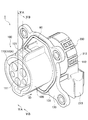
- FIG. 1 is a perspective view showing a charging inlet device according to the related art.
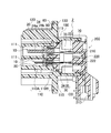
- FIG. 2 is a longitudinal sectional view (II-II sectional view of FIG. 1) of the charging inlet device according to the related art.
- FIG. 3 is an assembled perspective view of the charging inlet device according to the first embodiment as viewed from the front.
- FIG. 4 is an exploded perspective view showing the charging inlet device according to the first embodiment.
- 5A is a cross-sectional view taken along the line VA-VA in FIG. 5B is a cross-sectional view taken along the line VB-VB of FIG.
- FIG. 6 is a perspective view showing a terminal and a terminal displacement portion according to the first embodiment.
- FIG. 1 is a perspective view showing a charging inlet device according to the related art.
- FIG. 2 is a longitudinal sectional view (II-I sectional view of FIG. 1) of the charging inlet device according to the related art.
- FIG. 3 is an assembled perspective view of the charging inlet device according
- FIG. 7 is a view showing an assembled state of the charging inlet device according to the first embodiment to the vehicle body panel.
- FIG. 8 is an exploded perspective view showing the charging inlet device according to the second embodiment.
- FIG. 9A is a longitudinal sectional view (corresponding to a VA-VA sectional view of FIG. 3) of the charging inlet device according to the second embodiment.
- FIG. 9B is a longitudinal sectional view (corresponding to a VB-VB sectional view of FIG. 3) of the charging inlet device according to the second embodiment.
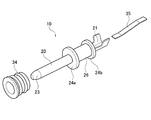
- FIG. 10A is a perspective view illustrating a terminal and a terminal displacement portion according to the second embodiment.
- FIG. 10B is a perspective view showing a terminal according to the second embodiment.
- FIG. 11 is an exploded perspective view showing the charging inlet device according to the third embodiment.
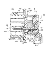
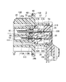
- FIG. 12A is a longitudinal sectional view (corresponding to the VA-VA sectional view of FIG. 3) of the charging inlet device according to the third embodiment.
- 12B is a longitudinal sectional view (corresponding to the VB-VB sectional view of FIG. 3) of the charging inlet device according to the third embodiment.
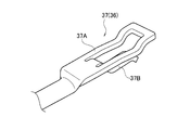
- FIG. 13A is a perspective view illustrating a terminal and a terminal displacement portion according to the third embodiment.
- FIG. 13B is a perspective view showing a terminal and a terminal displacement portion according to the third embodiment.
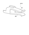
- FIG. 13C is a perspective view illustrating a terminal and a terminal displacement portion according to the third embodiment.
- a charging inlet device including an inlet connector as a connector according to the present invention will be described with reference to the drawings.
- the same or similar parts are denoted by the same or similar reference numerals.
- the drawings are schematic and ratios of dimensions and the like are different from actual ones. Accordingly, specific dimensions and the like should be determined in consideration of the following description. Moreover, the part from which the relationship and ratio of a mutual dimension differ also in between drawings may be contained.
- the charging inlet device 1 is configured so that a charging connector (not shown) provided with a counterpart terminal (not shown) is fitted.
- the charging inlet device 1 includes an inlet connector 100 and a rear connector 200 attached to the inlet connector 100.
- the inlet connector 100 includes a connector housing 110 in which a plurality of terminals 10 are provided, an exterior hood 120 that covers the periphery of the connector housing 110, and a vehicle body mounting flange 130 that protrudes outside the exterior hood 120. .
- the connector housing 110 includes a front housing 110A disposed in the exterior hood 120 and an inner housing 110B attached to the rear connector 200 side of the front housing 110A via the packing 50.
- the front housing 110A is formed integrally with the exterior hood 120 and the vehicle body mounting flange 130.
- the front housing 110 ⁇ / b> A is formed with a plurality of terminal accommodating chambers 111 for accommodating a plurality of terminals 10.
- a connector protrusion 112 (see FIGS. 3 to 5B) for locking the rear connector 200 is provided on the outer periphery of the front housing 110A on the rear connector 200 side.
- the inner housing 110B is interposed between the front housing 110A and the rear connector 200. As shown in FIGS. 5A and 5B, the inner housing 110 ⁇ / b> B includes an inner main body portion 113 and an inner overhang portion 114 that projects from the inner main body portion 113 toward the rear connector 200.
- the inner main body 113 is provided with a plurality of terminal support portions 115 that are provided on the insertion side of a charging connector (not shown) and support the plurality of terminals 10.
- Each terminal 10 supported by the terminal support portion 115 includes a charging terminal, a signal terminal, a ground terminal, and the like. The configuration of each terminal 10 will be described later.
- the inner overhanging portion 114 is provided with an elastic arm 116 having a claw portion (not shown) protruding inward at the tip.
- the exterior hood 120 is provided with a lock 121 that holds the mating terminal (not shown).
- the vehicle body mounting flange 130 can contact the vehicle body panel P (see FIG. 7), and a packing groove 131 into which the packing 60 is inserted is formed on the front surface of the vehicle body mounting flange 130.
- the rear connector 200 is attached to the front housing 110A of the inlet connector 100 while the inner housing 110B to which the terminals 10 are fixed is attached.
- the rear connector 200 includes a rear main body 210 and a wire lead-out terminal 220 provided in the rear main body 210.
- the rear main body 210 includes a rear projecting portion 211 formed with an engagement hole 211A that engages with a claw portion (not shown) of the elastic arm 116 provided in the inner housing 110B, and an outer side of the rear main body 210.
- An engagement arm 212 that engages with a connector protrusion 112 provided on the front housing 110A is provided (see FIGS. 5A and 5B).
- the rear body portion 210 is further provided with a connector insertion portion 213 provided along a direction CD (downward in the first embodiment) orthogonal to the charging connector insertion direction ID (that is, the movement direction of the mating terminal). Yes.
- the wire lead-out terminal 220 is insert-molded in the rear connector 200 and is bent in an L shape from the charging connector insertion direction ID toward the orthogonal direction CD. That is, one end of the wire lead-out terminal 220 protrudes from the rear connector 200 toward the inner housing 110 ⁇ / b> B and is connected to the terminal 10. On the other hand, the other end of the wire lead-out terminal 220 protrudes into the connector insertion portion 213 of the rear connector 200 and is connected to a terminal (not shown) in the connector C (see FIG. 7) fixed to the end of the wire W. .
- One of the plurality of wire lead terminals 220 is connected to the ground terminal of the plurality of terminals 10 and is not guided into the connector insertion portion 213 but protrudes from the rear body portion 210 toward the inlet connector 100 side. It is configured as.
- the ground portion 221 is electrically connected to the vehicle body panel P when the charging inlet device 1 is assembled to the vehicle body panel P (see FIG. 7) and the vehicle body mounting flange 130 and the vehicle body panel P are fastened by bolts or the like.
- FIG. 6 is a perspective view showing the terminal 10 and the terminal displacement portion 30 according to the first embodiment.
- the terminal 10 is connected by relative movement with a counterpart terminal (not shown).
- the terminal 10 is disposed in the terminal accommodating chamber 111 and has a cylindrical counterpart terminal contact portion 20 that contacts a counterpart terminal (not shown), and an inner side than the counterpart terminal contact portion 20. It is comprised by the terminal displacement part 30 provided in the housing 110B side.
- the tip of the mating terminal contact portion 20 is provided with an insulating (resin-made) tip portion 20A that prevents the user's fingers from coming into contact with the mating terminal contact portion 20.
- the terminal displacement portion 30 supports the terminal 10 so as to be displaceable in the direction CD orthogonal to the insertion direction ID of the charging connector (specifically, the vertical direction UD, the horizontal direction LR, and the tilt directions I1, I2 in FIG. 6). .
- the terminal displacement part 30 is formed integrally with the counterpart terminal contact part 20.
- the terminal displacement portion 30 is formed on the plate-like first plate portion 31 located on the terminal support portion 115 side as a support location of the inner housing 110 ⁇ / b> B, and on the counterpart terminal contact portion 20 side of the terminal 10.
- the second plate portion 32 is located, and the twisted portion 33 is twisted about 90 degrees between the first plate portion 31 and the second plate portion 32.
- the first plate portion 31 can be bent and deformed in the vertical direction UD, and the counterpart terminal contact portion 20 can be displaced with respect to the vertical direction UD.
- the first plate portion 31 is fixed to the terminal support portion 115 and connected to the wire lead-out terminal 220 of the rear connector 200.
- the first plate portion 31 and the wire lead-out terminal 220 are connected by welding such as resistance welding, for example.
- the second plate portion 32 is orthogonal to the first plate portion 31 by the twisted portion 33.
- the second plate portion 32 can bend and deform in the left-right direction LR, and can displace the mating terminal contact portion 20 with respect to the left-right direction LR.
- the first plate portion 31 and the second plate portion 32 can displace the mating terminal contact portion 20 in the tilt directions I1 and I2 by the above-described bending deformation.
- FIG. 7 is a diagram illustrating an assembled state of the charging inlet device 1 according to the first embodiment to the vehicle body panel P.
- the inner housing 110 ⁇ / b> B to which the terminals 10 are fixed is attached to the rear connector 200 via the packing 70 and the assembly 80. Then, the rear connector 200 to which the terminals 10 and the inner housing 110 ⁇ / b> B are attached is assembled to the front housing 110 ⁇ / b> A via the packing 90 to form the charging inlet device 1.
- the charging inlet device 1 is inserted into the inlet mounting hole P ⁇ b> 1 of the vehicle body panel P from the inside of the vehicle body panel P, and the vehicle body mounting flange 130 is abutted against the vehicle body panel P. Finally, the body mounting flange 130 and the body panel P are fastened with bolts or the like to complete.
- the connector C attached to the electric wire W routed on the vehicle body side may be fitted into the connector insertion portion 213 of the rear connector 200 when the charging inlet device 1 is assembled. After being fastened to the vehicle body panel P with a bolt or the like, it may be fitted into the connector insertion portion 213 of the rear connector 200.
- the terminal 10 is moved by the terminal displacement portion 30 in the up-down direction UD, the left-right direction LR, or the inclination direction I1, By being displaceable with respect to I2, the axial center of the terminal 10 is displaced (so-called alignment) in accordance with the inclination of the counterpart terminal. For this reason, the insertion force of a charging connector reduces and the malfunction resulting from this insertion force can be prevented. That is, the load on the mating terminal contact portion 20 of the terminal 10 is reduced, and the durability of the terminal 10 is improved. Moreover, since the other party terminal contact part 20 itself of the terminal 10 does not deform
- the terminal displacement portion 30 is formed by the first plate portion 31, the second plate portion 32, and the twisted portion 33, which are formed integrally with the mating terminal contact portion 20 of the terminal 10. .
- an additional member is not required for forming the terminal displacement part 30, and the increase in the manufacturing cost of the charging inlet apparatus 1 can be suppressed.
- the terminal 10 is moved in any direction by the terminal displacement portion 30 (the vertical direction UD, the horizontal direction LR in FIG. , I2).
- the twist angle of the twisted portion 33 is not necessarily about 90 degrees, and can be arbitrarily set as long as the terminal 10 can be displaced in any direction.
- FIG. 8A, and 9B are diagrams showing the charging inlet device 2 according to the second embodiment.
- FIG. 10A is a perspective view showing the terminal 10 and the terminal displacement portion 30 according to the second embodiment.
- FIG. 10B is a perspective view showing the terminal 10 according to the second embodiment.
- symbol is attached
- the terminal displacement portion 30 is formed integrally with the terminal 10 (the counterpart terminal contact portion 20).
- the terminal displacement portion 30 is formed separately from the terminal 10.
- the terminal 10 includes a conductive terminal main body 10A and an insulating insulating member 10B fixed to the terminal main body 10A.
- the terminal body 10A is formed by bending a conductive plate having a predetermined shape by press working.
- the terminal body 10A includes a cylindrical mating terminal contact portion 20 with which a mating terminal (not shown) contacts, a terminal side crimping portion 21 to which a conductive member 35 of a terminal displacement portion 30 described later is caulked and fixed, It has a connecting portion 22 (see FIG. 10B) that connects them.
- the insulating member 10B includes a tip portion 23 protruding forward from the tip of the mating terminal contact portion 20, a terminal holding portion 24 disposed on the outer periphery of the connecting portion 22 on the rear end side of the mating terminal contact portion 20, It is comprised in the other party terminal contact part 20 and the communication part 25 which connects between the front-end
- the ribs 24a and 24b are projected from both ends of the outer periphery of the terminal holding portion 24 over the entire periphery.
- a fitting recess 26 formed by a pair of ribs 24 a and 24 b is provided on the outer periphery of the terminal holding portion 24.
- the terminal displacement portion 30 includes a cylindrical elastic support member 34 that supports the terminal 10 with the terminal support portion 115 of the inner housing 110B, and a mating terminal contact portion of the terminal 10. And a plate-like conductive member 35 to which the opposite side of 20 is connected.
- the elastic support member 34 is formed of an elastic body such as a rubber material.
- the elastic support member 34 is attached to the fitting recess 26 while being positioned by the pair of ribs 24a and 24b.
- the conductive member 35 has flexibility and relays between the terminal 10 and the electric wire drawing terminal 220 of the rear connector 200.
- One end of the conductive member 35 is crimped and fixed to the terminal side crimping portion 21 and connected to the terminal 10.
- the other end of the conductive member 35 is caulked and fixed to a rear side caulking portion 222 (see FIGS. 8, 9A, and 9B) provided at the end of the wire lead-out terminal 220.
- the terminal 10 is fitted into the terminal holding hole 115 (see FIGS. 8, 9A, and 9B) formed in the inner housing 110B via the elastic support member. By joining, it is fixed to the inner housing 110B.
- the rib 24b on the rear side provided on the outer periphery of the terminal holding portion 24 and the elastic support member 34 are in close contact with the inner surface of the terminal support portion 115.
- the terminal 10 can displace the direction of an axial center with respect to the inner housing 110B by using the rib 24b as a fulcrum by elastic deformation of the elastic support member 34.
- the conductive member 35 has flexibility, even if the terminal 10 is displaced, the connection between the terminal 10 and the wire lead-out terminal 220 can be maintained.
- the terminal displacement portion 30 is formed by the elastic support member 34 and the flexible conductive member 35, so that the elastic support member 34 is inserted when the charging connector is inserted into the charging inlet device 2.
- the displacement of the terminal 10 can be supported freely, and the terminal 10 and the wire drawing terminal 220 can be relayed by the conductive member 35.
- the axial center of the terminal 10 is displaced (so-called alignment) in accordance with the inclination of the counterpart terminal, so that the insertion force of the charging connector is reduced, resulting from this insertion force. You can prevent problems.
- FIG. 12A and FIG. 12B are views showing a charging inlet device 3 according to the third embodiment.
- 13A to 13C are perspective views showing the terminal 10 and the terminal displacement portion 30 according to the third embodiment.
- symbol is attached
- the terminal displacement portion 30 is formed separately from the terminal 10.
- a part of the terminal displacement portion 30 is formed integrally with the terminal 10, and the elastic support member 34 of the terminal displacement portion 30 is formed separately from the terminal 10.
- the terminal displacement portion 30 includes a cylindrical elastic support member 34 that supports the terminal 10 with the terminal support portion 115 of the inner housing 110B, and the terminal 10 It is formed with the leaf
- the elastic support member 34 is attached to the fitting recess 26 in a state where the elastic support member 34 is positioned by a pair of ribs 24a and 24b provided on the outer periphery of the terminal holding portion 24, as in the second embodiment.
- the leaf spring contact portion 36 is formed integrally with the mating terminal contact portion 20 of the terminal 10.
- the leaf spring contact portion 36 is a large current leaf spring portion 37 provided on a thick terminal (for example, a charging terminal or a ground terminal) of the terminals 10 and a thin terminal (for example, a signal terminal) of the terminals 10.
- a small-current leaf spring portion 38 provided in the first and second current sources.
- the large-current leaf spring portion 37 includes a plate-like plate body portion 37A and a plate cut-out portion 37B cut and raised from the plate body portion 37A. It is configured. One end of the wire lead-out terminal 220 is sandwiched between the plate main body portion 37A and the plate cut and raised portion 37B.
- the small current leaf spring portion 38 is composed of a pair of sandwiching pieces 38A and 38B facing each other. One end of the wire lead-out terminal 220 is clamped by the pair of clamping pieces 38A and 38B.
- the terminal 10 is fitted into the terminal support portion 115 (see FIGS. 11, 12A, and 12B) formed in the inner housing 110B via the elastic support member 34. By joining, it is fixed to the inner housing 110B.
- the rear rib 24b provided on the outer periphery of the terminal holding portion 24 and the elastic support member 34 are in close contact with the inner surface of the terminal support portion 115.
- the terminal 10 can displace the direction of an axial center with respect to the inner housing 110B by using the rib 24b as a fulcrum by elastic deformation of the elastic support member 34.
- the leaf spring contact portion 36 holds one end of the wire lead-out terminal 220, the connection between the terminal 10 and the wire lead-out terminal 220 can be maintained even if the terminal 10 is displaced.
- the terminal displacement portion 30 is formed by the elastic support member 34 and the leaf spring contact portion 36, the terminal is moved by the elastic support member 34 when the charging connector is inserted into the charging inlet device 1. 10 can be freely supported, and the connection between the terminal 10 (the counterpart terminal contact portion 20) and the wire lead-out terminal 220 is maintained by the leaf spring contact portion. For this reason, as in the first and second embodiments, the axial center of the terminal 10 is displaced (so-called alignment) in accordance with the inclination of the mating terminal, so that the insertion force of the charging connector is reduced. It is possible to prevent problems caused by
- the embodiment of the present invention can be modified as follows. Specifically, in the first to third embodiments, the terminal displacement portion 30 has been described as being provided in the inlet connector 100 of the charging inlet device 1, but the present invention is not limited to this, and the rear connector 200 is not limited thereto. It may be provided in the vicinity of the wire lead-out terminal 220. Moreover, the terminal displacement part 30 may be provided in the charge connector, and of course can be applied to other various connectors.
- the direction in which the electric wire W is drawn is described as being below the rear connector 200.
- the direction is not limited to this. There may be.
Landscapes
- Engineering & Computer Science (AREA)
- Power Engineering (AREA)
- Transportation (AREA)
- Mechanical Engineering (AREA)
- Details Of Connecting Devices For Male And Female Coupling (AREA)
- Connector Housings Or Holding Contact Members (AREA)
Abstract
コネクタ(100)が、相手側端子との相対的移動によって接続される端子(10)と、端子(10)を支持するコネクタハウジング(110B)と、相手側端子との相対移動方向の直交方向(CD)に端子(10)を変位自在に支持する端子変位部(30)とを備える。
Description
本発明は、電気自動車やハイブリッド電気自動車等の車両に使用されるコネクタに関し、特に、充電インレット装置に使用されるインレットコネクタに関する。
電気自動車(EV)やハイブリッド電気自動車(HEV)等の車体に搭載されるバッテリを充電するために、車両には相手側コネクタとしての充電コネクタが嵌合される充電インレット装置が設けられる(特許文献1参照)。この充電インレット装置について、図1及び図2を参照しながら説明する。
図1に示すように、充電インレット装置500は、インレットコネクタ510と、インレットコネクタ510に回動自在に設けられるキャップ520とを有する。
インレットコネクタ510は、内部に端子530(図2参照)が複数設けられるコネクタハウジング511と、コネクタハウジング511の周囲を覆う外装フード512と、外装フード512の外側に突設された車体取付フランジ部513とを有する。
図2に示すように、各端子530は、コネクタハウジング511に形成される端子収容室511A内に収容され、相手側端子(不図示)との相対的移動によって接続される。各端子530は、端子収容室511A内に完全に収容されると、各ランス511Bに係止される。各ランス511Bの係止力によって各端子530は、端子収容室511A内に位置決め状態で収容される。このとき、各端子530は、充電インレット装置500に対する充電コネクタの挿入方向IDに沿ってそれぞれ配置されている。
ところで、充電コネクタを充電インレット装置500に挿入する際、必ずしも端子530の長手方向に対して充電コネクタの挿入方向IDが一致するとは限らなかった。つまり、充電コネクタがコネクタハウジング511に対して傾斜して挿入されると、相手側端子の傾斜に合わせて端子530の軸芯が傾斜する。
このため、充電インレット装置500への充電コネクタの挿入力が増大し、この増大した挿入力に起因する不具合(例えば、端子530の耐久性の低下や端子530と相手側端子との接続信頼性の低下)が生じてしまう。
本発明は、相手側コネクタがコネクタハウジングに対して傾斜して挿入される場合であっても、相手側コネクタの挿入力を低減し、この挿入力に起因する不具合を解消できるコネクタを提供することを目的とする。
実施形態に係るコネクタは、相手側端子との相対的移動によって接続される端子と、前記端子を支持するコネクタハウジングと、前記相手側端子との相対移動方向の直交方向に前記端子を変位自在に支持する端子変位部とを備える。
また、前記端子変位部は、前記コネクタハウジングの支持箇所側に位置する第1プレート部と、前記端子の相手端子接触部側に位置する第2プレート部と、前記第1プレート部と前記第2プレート部との間で、前記第1プレート部と前記第2プレート部とを直交させる捻り部とを備えてもよい。
また、前記端子変位部は、前記端子を前記コネクタハウジングとの間で支持する弾性支持部材と、前記端子の相手端子接触部の反対側が接続された可撓性の導電部材とを備えてもよい。
また、記端子変位部は、前記端子を前記コネクタハウジングとの間で支持する弾性支持部材と、前記端子の相手端子接触部の反対側に設けられた板バネ接触部とを備えてもよい。
上述の構成によれば、端子が端子変位部により変位自在である。このため、相手側コネクタがコネクタハウジングに対して傾斜して挿入される場合であっても、相手側端子の傾斜に合わせて端子の軸芯が変位(いわゆる、調芯)する。これにより、充電コネクタの挿入力が低減し、この挿入力に起因する不具合を防止できる。
本発明に係るコネクタとしてのインレットコネクタを備えた充電インレット装置について、図面を参照しながら説明する。なお、以下の図面の記載において、同一または類似の部分には、同一または類似の符号を付している。ただし、図面は模式的なものであり、各寸法の比率などは現実のものとは異なることに留意すべきである。したがって、具体的な寸法などは以下の説明を参酌して判断すべきである。また、図面相互間においても互いの寸法の関係や比率が異なる部分が含まれ得る。
(充電インレット装置の構成)
第1実施形態に係る充電インレット装置1の構成について、図面を参照しながら説明する。図3~図5Bは、第1実施形態に係る充電インレット装置1を示す図である。
第1実施形態に係る充電インレット装置1の構成について、図面を参照しながら説明する。図3~図5Bは、第1実施形態に係る充電インレット装置1を示す図である。
図3~図5Bに示すように、充電インレット装置1は、相手側端子(不図示)が設けられた充電コネクタ(不図示)が嵌合するように構成されている。充電インレット装置1は、インレットコネクタ100と、インレットコネクタ100に取り付けられるリアコネクタ200とを備えている。
インレットコネクタ100は、内部に端子10が複数設けられるコネクタハウジング110と、コネクタハウジング110の周囲を覆う外装フード120と、外装フード120の外側に突設された車体取付フランジ130とを有している。
コネクタハウジング110は、外装フード120内に配置されるフロントハウジング110Aと、パッキン50を介してフロントハウジング110Aのリアコネクタ200側に取り付けられるインナーハウジング110Bとによって構成されている。
フロントハウジング110Aは、外装フード120及び車体取付フランジ130と一体に形成されている。フロントハウジング110Aには、複数の端子10を収容する複数の端子収容室111が形成されている。フロントハウジング110Aのリアコネクタ200側の外周には、リアコネクタ200が係止するコネクタ突部112(図3~図5B参照)が設けられている。
インナーハウジング110Bは、フロントハウジング110Aとリアコネクタ200との間に介在されている。インナーハウジング110Bは、図5A、5Bに示すように、インナー本体部113と、インナー本体部113からリアコネクタ200側に張り出したインナー張出部114とを備えている。
インナー本体部113には、充電コネクタ(不図示)の挿入側に設けられて複数の端子10を支持する複数の端子支持部115が設けられている。端子支持部115に支持される各端子10は、充電用端子や信号用端子、アース端子等によって構成されている。各端子10の構成については、後述する。インナー張出部114には、内側に向けて突出する爪部(不図示)が先端に形成された弾性アーム116が設けられている。
外装フード120には、相手側端子(不図示)との嵌合を保持するロック部121が設けられている。車体取付フランジ130は、車体パネルP(図7参照)に当接可能であり、車体取付フランジ130の前面には、パッキン60が挿入されるパッキン溝131が形成されている。
リアコネクタ200は、端子10が固定されたインナーハウジング110Bが取り付けられるとともに、インレットコネクタ100のフロントハウジング110Aに装着される。リアコネクタ200は、リア本体部210と、リア本体部210内に設けられる電線引出用端子220とを備えている。
リア本体部210には、インナーハウジング110Bに設けられた弾性アーム116の爪部(不図示)と係合する係合孔211Aが形成されたリア張出部211と、リア本体部210の外側でフロントハウジング110Aに設けられたコネクタ突部112に係合する係合アーム212とが設けられている(図5A、5B参照)。リア本体部210には、充電コネクタの挿入方向ID(すなわち、相手側端子の移動方向)の直交方向CD(第1実施形態では、下方)に沿って設けられるコネクタ挿入部213がさらに設けられている。
電線引出用端子220は、リアコネクタ200にインサート成型されており、充電コネクタの挿入方向IDから直交方向CDに向かってL字状に屈曲している。つまり、電線引出用端子220の一端は、リアコネクタ200からインナーハウジング110B側に突出し、端子10に接続される。一方、電線引出用端子220の他端は、リアコネクタ200のコネクタ挿入部213内に突出し、電線Wの端末に固定されたコネクタC(図7参照)内の端子(不図示)と接続される。
複数の電線引出用端子220の一つは、複数の端子10のうちのアース端子に接続され、コネクタ挿入部213内に導かれずに、リア本体部210からインレットコネクタ100側に突出したアース部221として構成されている。アース部221は、充電インレット装置1が車体パネルP(図7参照)に組み付けられて車体取付フランジ130と車体パネルPとがボルト等によって締結されると、車体パネルPと導通接続される。
(端子の構成)
次に、上述した端子10の構成について、図4~図6を参照しながら説明する。図6は、第1実施形態に係る端子10及び端子変位部30を示す斜視図である。
次に、上述した端子10の構成について、図4~図6を参照しながら説明する。図6は、第1実施形態に係る端子10及び端子変位部30を示す斜視図である。
図4及び図6に示すように、端子10は、相手側端子(不図示)との相対的移動によって接続される。図6に示すように、端子10は、端子収容室111内に配置されて相手側端子(不図示)と接触する筒状の相手側端子接触部20と、相手側端子接触部20よりもインナーハウジング110B側に設けられる端子変位部30とによって構成されている。
相手側端子接触部20の先端には、ユーザの手指が相手側端子接触部20に接触することを防止する絶縁性(樹脂製)の先端部20Aが設けられている。
端子変位部30は、充電コネクタの挿入方向IDの直交方向CD(具体的には、図6の上下方向UDや左右方向LR、傾斜方向I1,I2)に端子10を変位自在に支持している。端子変位部30は、相手側端子接触部20と一体に形成されている。
図6に示すように、端子変位部30は、インナーハウジング110Bの支持箇所としての端子支持部115側に位置する板状の第1プレート部31と、端子10の相手側端子接触部20側に位置する第2プレート部32と、第1プレート部31と第2プレート部32との間で約90度捻られた捻り部33とによって形成されている。
第1プレート部31は、上下方向UDに撓み変形可能であり、該上下方向UDに対して相手側端子接触部20を変位できる。第1プレート部31は、端子支持部115に固定されてリアコネクタ200の電線引出用端子220と接続される。第1プレート部31と電線引出用端子220とは、例えば、抵抗溶接等の溶接により接続される。
第2プレート部32は、捻り部33により第1プレート部31に対して直交している。第2プレート部32は、左右方向LRに撓み変形可能であり、該左右方向LRに対して相手側端子接触部20を変位できる。
これらの第1プレート部31及び第2プレート部32は、上述した各々の撓み変形により、傾斜方向I1,I2に対しても相手側端子接触部20を変位できる。
(充電インレット装置の取付)
次に、上述した充電インレット装置1の車体パネルPへの取付作業について、図4及び図7を参照しながら簡単に説明する。図7は、第1実施形態に係る充電インレット装置1の車体パネルPへの組付状態を示す図である。
次に、上述した充電インレット装置1の車体パネルPへの取付作業について、図4及び図7を参照しながら簡単に説明する。図7は、第1実施形態に係る充電インレット装置1の車体パネルPへの組付状態を示す図である。
先ず、図4に示すように、リアコネクタ200に、パッキン70及びアセンブリー80を介して、端子10が固定されたインナーハウジング110Bを装着する。そして、端子10及びインナーハウジング110Bが装着されたリアコネクタ200を、パッキン90を介してフロントハウジング110Aに組み付けて、充電インレット装置1を形成する。
次に、図7に示すように、車体パネルPの内側より車体パネルPのインレット取付穴P1に、充電インレット装置1を挿入し、車体取付フランジ130を車体パネルPに突き当てる。最後に、車体取付フランジ130と車体パネルPとをボルト等によって締結すれば完了する。
ここで、車体側に配策される電線Wに取り付けられたコネクタCは、充電インレット装置1の組立時にリアコネクタ200のコネクタ挿入部213に嵌合されてもよく、また、充電インレット装置1が車体パネルPにボルト等によって締結された後にリアコネクタ200のコネクタ挿入部213に嵌合されてよい。
(作用・効果)
以上説明した第1実施形態では、充電コネクタがフロントハウジング110Aに対して傾斜して挿入される場合であっても、端子10が端子変位部30により上下方向UDや左右方向LR或いは傾斜方向I1,I2に対して変位自在であることで、相手側端子の傾斜に合わせて端子10の軸芯が変位(いわゆる、調芯)する。このため、充電コネクタの挿入力が低減し、この挿入力に起因する不具合を防止できる。つまり、端子10の相手側端子接触部20への負荷が低減して端子10の耐久性が向上する。また、端子10の相手側端子接触部20自体が変形しないため、端子10と相手側端子(不図示)との接続信頼性の低下を抑制できる。
以上説明した第1実施形態では、充電コネクタがフロントハウジング110Aに対して傾斜して挿入される場合であっても、端子10が端子変位部30により上下方向UDや左右方向LR或いは傾斜方向I1,I2に対して変位自在であることで、相手側端子の傾斜に合わせて端子10の軸芯が変位(いわゆる、調芯)する。このため、充電コネクタの挿入力が低減し、この挿入力に起因する不具合を防止できる。つまり、端子10の相手側端子接触部20への負荷が低減して端子10の耐久性が向上する。また、端子10の相手側端子接触部20自体が変形しないため、端子10と相手側端子(不図示)との接続信頼性の低下を抑制できる。
第1実施形態では、端子変位部30は、第1プレート部31、第2プレート部32及び捻り部33によって形成されて、これらが端子10の相手側端子接触部20と一体に形成されている。このため、端子変位部30を形成するために別途部材が必要にならずに、充電インレット装置1の製造コストの増大を抑制できる。
特に、捻り部33により第1プレート部31と第2プレート部32とが直交しているので、端子10が端子変位部30によりあらゆる方向(図6の上下方向UDや左右方向LR、傾斜方向I1,I2)に変位し易くなっている。なお、捻り部33の捻り角度については、必ずしも約90度である必要はなく、端子10があらゆる方向に変位できる角度であれば任意に設定できる。
次に、第2実施形態に係る充電インレット装置2について、図面を参照しながら説明する。図8、図9A、図9Bは、第2実施形態に係る充電インレット装置2を示す図である。図10Aは、第2実施形態に係る端子10及び端子変位部30を示す斜視図である。図10Bは、第2実施形態に係る端子10を示す斜視図である。なお、上述した第1実施形態に係る充電インレット装置1と同一部分には同一の符号を付して、相違する部分を主として説明する。
上述した第1実施形態では、端子変位部30が端子10(相手側端子接触部20)と一体に形成されている。これに対して、第2実施形態では、端子変位部30が端子10と別体に形成されている。
まず、端子10の構成について説明する。図8~図10Bに示すように、端子10は、導電性の端子本体10Aと、端子本体10Aに固定された絶縁性の絶縁部材10Bとによって構成されている。
端子本体10Aは、所定形状の導電性プレートをプレス加工で折り曲げることによって形成されている。端子本体10Aは、相手側端子(不図示)が接触する筒状の相手側端子接触部20と、後述する端子変位部30の導電部材35が加締め固定される端子側加締部21と、これらを連結する繋ぎ部22(図10B参照)とを備えている。
絶縁部材10Bは、相手側端子接触部20の先端より前方に突出する先端部23と、相手側端子接触部20の後端側である繋ぎ部22の外周に配置された端子保持部24と、相手側端子接触部20内に設けられて先端部23と端子保持部24との間を連結する連通部25とによって構成されている。
端子保持部24の外周の両端には、リブ24a,24bが全周に亘って突設されている。端子保持部24の外周には、一対のリブ24a,24bにより形成された嵌合凹部26が設けられている。
次に、端子変位部30の構成について説明する。図8~図10Bに示すように、端子変位部30は、端子10をインナーハウジング110Bの端子支持部115との間で支持する円筒状の弾性支持部材34と、端子10の相手側端子接触部20の反対側が接続された板状の導電部材35とによって形成されている。
弾性支持部材34は、ゴム材等の弾性体によって形成されている。弾性支持部材34は、一対のリブ24a,24bにより位置決めされた状態で、嵌合凹部26に装着される。
導電部材35は、可撓性を有するとともに、端子10とリアコネクタ200の電線引出用端子220とを中継している。導電部材35の一端は、端子側加締部21に加締め固定され、端子10と接続されている。一方、導電部材35の他端は、電線引出用端子220の端部に設けられたリア側加締部222(図8、図9A、図9B参照)に加締め固定される。
このような第2実施形態に係る充電インレット装置2では、端子10は、弾性支持部材34を介して、インナーハウジング110Bに形成された端子保持孔115(図8、図9A、9B参照)に嵌合することでインナーハウジング110Bに固定されている。
そして、図9A、9Bに示すように、端子保持部24の外周に設けられた後側のリブ24bと弾性支持部材34とが端子支持部115の内面に密着している。これにより、端子10は、弾性支持部材34の弾性変形によって、リブ24bを支点に軸芯の向きをインナーハウジング110Bに対して変位できる。また、導電部材35が可撓性を有しているため、端子10が変位しても、端子10と電線引出用端子220との接続を保持できる。
以上説明した第2実施形態では、端子変位部30が弾性支持部材34と可撓性の導電部材35とによって形成されることで、充電インレット装置2への充電コネクタの挿入時に、弾性支持部材34により端子10の変位を自在に支持でき、導電部材35により端子10と電線引出用端子220とを中継できる。これにより、第1実施形態と同様に、相手側端子の傾斜に合わせて端子10の軸芯が変位(いわゆる、調芯)するため、充電コネクタの挿入力が低減し、この挿入力に起因する不具合を防止できる。
次に、第3実施形態に係る充電インレット装置3について、図面を参照しながら説明する。図11、図12A、図12Bは、第3実施形態に係る充電インレット装置3を示す図である。図13A~13Cは、第3実施形態に係る端子10及び端子変位部30を示す斜視図である。なお、上述した第2実施形態に係る充電インレット装置2と同一部分には同一の符号を付して、相違する部分を主として説明する。
上述した第2実施形態では、端子変位部30が端子10と別体に形成されている。これに対して、第3実施形態では、端子変位部30の一部が端子10と一体に形成され、端子変位部30の弾性支持部材34が端子10と別体に形成されている。
具体的には、図11~図13Cに示すように、端子変位部30は、端子10をインナーハウジング110Bの端子支持部115との間で支持する円筒状の弾性支持部材34と、端子10の相手側端子接触部20の反対側に設けられた板バネ接触部36とによって形成されている。
弾性支持部材34は、第2実施形態と同様に、端子保持部24の外周に設けられた一対のリブ24a,24bにより位置決めされた状態で、嵌合凹部26に装着される。
板バネ接触部36は、端子10の相手側端子接触部20と一体に形成されている。板バネ接触部36は、端子10のうちの太い端子(例えば、充電用端子やアース端子)に設けられる大電流用板バネ部37と、端子10のうちの細い端子(例えば、信号用端子)に設けられる小電流用板バネ部38とによって構成されている。
大電流用板バネ部37は、図12A、図12B、図13A、図13Bに示すように、板状のプレート本体部37Aと、プレート本体部37Aから切り起こされたプレート切起部37Bとによって構成されている。プレート本体部37A及びプレート切起部37Bによって、電線引出用端子220の一端を挟持する。
小電流用板バネ部38は、図12B及び図13Cに示すように、互いに対向する一対の挟持片38A,38Bとによって構成されている。一対の挟持片38A,38Bとによって、電線引出用端子220の一端を挟持する。
このような第3実施形態に係る充電インレット装置3では、端子10は、弾性支持部材34を介して、インナーハウジング110Bに形成された端子支持部115(図11、図12A、12B参照)に嵌合することでインナーハウジング110Bに固定されている。
そして、図12A、12Bに示すように、端子保持部24の外周に設けられた後側のリブ24bと弾性支持部材34とが端子支持部115の内面に密着している。これにより、端子10は、弾性支持部材34の弾性変形によって、リブ24bを支点に軸芯の向きをインナーハウジング110Bに対して変位できる。また、板バネ接触部36が電線引出用端子220の一端を挟持しているため、端子10が変位しても、端子10と電線引出用端子220との接続を保持できる。
以上説明した第3実施形態では、端子変位部30が弾性支持部材34と板バネ接触部36とによって形成されることで、充電インレット装置1への充電コネクタの挿入時に、弾性支持部材34により端子10の変位を自在に支持でき、板バネ接触部36により端子10(相手側端子接触部20)と電線引出用端子220との接続が保持される。このため、第1,第2実施形態と同様に、相手側端子の傾斜に合わせて端子10の軸芯が変位(いわゆる、調芯)するため、充電コネクタの挿入力が低減し、この挿入力に起因する不具合を防止できる。
上述したように、本発明の実施形態を通じて本発明の内容を開示したが、この開示の一部をなす論述及び図面は、本発明を限定するものであると理解すべきではない。この開示から当業者には様々な代替実施の形態、実施例及び運用技術が明らかとなる。
例えば、本発明の実施形態は、次のように変更することができる。具体的には、第1~第3実施形態では、端子変位部30は、充電インレット装置1のインレットコネクタ100に設けられるものとして説明したが、これに限定されるものではなく、リアコネクタ200の電線引出用端子220近傍に設けられていてもよい。また、端子変位部30は、充電コネクタに設けられていてもよく、その他の様々なコネクタに適用できることは勿論である。
また、第1~第3実施形態では、電線Wの引き出し方向としては、リアコネクタ200の下方であるものとして説明したが、これに限定されるものではなく、リアコネクタ200の上方や側方であってもよい。
このように、本発明は、ここでは記載していない様々な実施の形態などを含むことは勿論である。したがって、本発明の技術的範囲は、上述の説明から妥当な特許請求の範囲に係る発明特定事項によってのみ定められる。
特願2012-249023号(出願日:2012年11月13日)の全内容は、ここに援用される。
Claims (4)
- 相手側端子との相対的移動によって接続される端子と、
前記端子を支持するコネクタハウジングと、
前記相手側端子との相対移動方向の直交方向に前記端子を変位自在に支持する端子変位部と、
を備えたコネクタ。 - 前記端子変位部は、
前記コネクタハウジングの支持箇所側に位置する第1プレート部と、
前記端子の相手端子接触部側に位置する第2プレート部と、
前記第1プレート部と前記第2プレート部との間で、前記第1プレート部と前記第2プレート部とを直交させる捻り部と、を備えた
請求項1に記載のコネクタ。 - 前記端子変位部は、
前記端子を前記コネクタハウジングとの間で支持する弾性支持部材と、
前記端子の相手端子接触部の反対側が接続された可撓性の導電部材と、を備えた
請求項1に記載のコネクタ。 - 記端子変位部は、
前記端子を前記コネクタハウジングとの間で支持する弾性支持部材と、
前記端子の相手端子接触部の反対側に設けられた板バネ接触部と、を備えた
請求項1に記載のコネクタ。
Priority Applications (3)
| Application Number | Priority Date | Filing Date | Title |
|---|---|---|---|
| EP13854659.3A EP2922152B1 (en) | 2012-11-13 | 2013-11-08 | Connector |
| CN201380059107.7A CN104823331A (zh) | 2012-11-13 | 2013-11-08 | 连接器 |
| US14/698,256 US9531100B2 (en) | 2012-11-13 | 2015-04-28 | Connector |
Applications Claiming Priority (2)
| Application Number | Priority Date | Filing Date | Title |
|---|---|---|---|
| JP2012249023A JP6071448B2 (ja) | 2012-11-13 | 2012-11-13 | コネクタ |
| JP2012-249023 | 2012-11-13 |
Related Child Applications (1)
| Application Number | Title | Priority Date | Filing Date |
|---|---|---|---|
| US14/698,256 Continuation US9531100B2 (en) | 2012-11-13 | 2015-04-28 | Connector |
Publications (1)
| Publication Number | Publication Date |
|---|---|
| WO2014077196A1 true WO2014077196A1 (ja) | 2014-05-22 |
Family
ID=50731108
Family Applications (1)
| Application Number | Title | Priority Date | Filing Date |
|---|---|---|---|
| PCT/JP2013/080220 Ceased WO2014077196A1 (ja) | 2012-11-13 | 2013-11-08 | コネクタ |
Country Status (5)
| Country | Link |
|---|---|
| US (1) | US9531100B2 (ja) |
| EP (1) | EP2922152B1 (ja) |
| JP (1) | JP6071448B2 (ja) |
| CN (1) | CN104823331A (ja) |
| WO (1) | WO2014077196A1 (ja) |
Cited By (3)
| Publication number | Priority date | Publication date | Assignee | Title |
|---|---|---|---|---|
| US20230031879A1 (en) * | 2021-07-28 | 2023-02-02 | Yazaki Corporation | Connection terminal |
| US20230238811A1 (en) * | 2022-01-24 | 2023-07-27 | Tyco Electronics (Suzhou) Ltd. | Charging Base |
| US12459449B2 (en) | 2020-04-28 | 2025-11-04 | Nissan Motor Co., Ltd. | Wire harness routing structure for chargeable vehicle |
Families Citing this family (28)
| Publication number | Priority date | Publication date | Assignee | Title |
|---|---|---|---|---|
| JP5981294B2 (ja) * | 2012-10-12 | 2016-08-31 | 矢崎総業株式会社 | 充電インレット装置 |
| DE202012011808U1 (de) * | 2012-12-10 | 2014-03-13 | Rosenberger Hochfrequenztechnik Gmbh & Co. Kg | Verbindungsvorrichtung |
| KR101794427B1 (ko) | 2012-12-25 | 2017-11-06 | 비와이디 컴퍼니 리미티드 | 배터리 |
| JP2016506043A (ja) | 2012-12-25 | 2016-02-25 | ビーワイディー カンパニー リミテッド | 電池 |
| JP6319633B2 (ja) * | 2015-01-28 | 2018-05-09 | 住友電装株式会社 | 機器用コネクタ |
| US9337577B1 (en) * | 2015-03-31 | 2016-05-10 | Tyco Electronics Corporation | Floatable connector |
| DE102016206002A1 (de) * | 2016-04-11 | 2017-10-12 | Bayerische Motoren Werke Aktiengesellschaft | Ladeanschlussmodul für ein Fahrzeug |
| JP6434938B2 (ja) * | 2016-08-10 | 2018-12-05 | 矢崎総業株式会社 | コネクタ |
| US20180056797A1 (en) * | 2016-08-31 | 2018-03-01 | Faraday&Future Inc. | Systems and methods for providing an intelligent charge handle for charging a vehicle battery |
| KR101928070B1 (ko) * | 2016-12-20 | 2018-12-11 | 주식회사 유라코퍼레이션 | 전기자동차용 인렛 |
| KR102662704B1 (ko) * | 2017-01-18 | 2024-05-02 | 삼성에스디아이 주식회사 | 배터리 시스템용 수동 서비스 분리 장치 |
| JP6764366B2 (ja) * | 2017-03-28 | 2020-09-30 | 矢崎総業株式会社 | ワイヤハーネス、及び、蓄電装置ユニット |
| JP6736510B2 (ja) * | 2017-03-28 | 2020-08-05 | 矢崎総業株式会社 | ワイヤハーネス、及び、蓄電装置ユニット |
| DE112018003970T5 (de) * | 2017-08-02 | 2020-04-16 | Sumitomo Wiring Systems, Ltd. | Ladestecker |
| US11101606B2 (en) * | 2017-08-02 | 2021-08-24 | Sumitomo Wiring Systems, Ltd. | Charging inlet |
| FR3095086B1 (fr) | 2019-04-12 | 2021-04-16 | Aptiv Tech Ltd | Procédé de fabrication d’un contact de puissance mâle et contact de puissance mâle |
| EP3745541B1 (de) * | 2019-05-31 | 2022-09-14 | ERICH JAEGER GmbH + Co. KG | Steckdose für eine kombinierte elektrische verbindung und datenverbindung |
| DE102020123476A1 (de) * | 2020-09-09 | 2022-03-10 | Phoenix Contact E-Mobility Gmbh | Ladedose mit Schnittstelle |
| CN112670736B (zh) * | 2020-12-01 | 2025-07-01 | 南京康尼新能源汽车零部件有限公司 | 一种兼容一体式枪壳和开半式枪壳的组件结构 |
| CN214625472U (zh) * | 2021-01-20 | 2021-11-05 | 泰科电子科技(苏州工业园区)有限公司 | 一种充电插座 |
| KR102578187B1 (ko) * | 2021-05-18 | 2023-09-13 | 주식회사 유라 | 자동차 충전 커넥터 |
| KR102578186B1 (ko) * | 2021-05-18 | 2023-09-13 | 주식회사 유라 | 자동차 충전 커넥터 |
| DE102021115051A1 (de) | 2021-06-10 | 2022-12-15 | Te Connectivity Germany Gmbh | Adaptersystem zur elektrischen Verbindung eines Steckverbinders einer Verkabelung mit unterschiedlichen Kontaktanordnungen verschiedener Ladebuchsen |
| CN114899669A (zh) * | 2022-05-03 | 2022-08-12 | 长春捷翼汽车零部件有限公司 | 一种充电接口接地结构及一种车辆 |
| US12135591B2 (en) * | 2022-07-06 | 2024-11-05 | Gm Cruise Holdings Llc | Environmental and electromagnetic seal for autonomous vehicle control systems |
| JP7642597B2 (ja) | 2022-10-20 | 2025-03-10 | 矢崎総業株式会社 | 充電インレットおよび充電インレットの組付け方法 |
| JP7596346B2 (ja) * | 2022-11-07 | 2024-12-09 | 矢崎総業株式会社 | コネクタ |
| JP7721228B2 (ja) | 2022-12-22 | 2025-08-12 | 矢崎総業株式会社 | 充電インレット |
Citations (10)
| Publication number | Priority date | Publication date | Assignee | Title |
|---|---|---|---|---|
| JPS59143285A (ja) * | 1983-02-04 | 1984-08-16 | ヒロセ電機株式会社 | 電気コネクタ用接触子及びそれを利用した電気コネクタ |
| JPH10228939A (ja) * | 1997-01-08 | 1998-08-25 | Connecteurs Cinch Sa | 雌型電気接点部材 |
| JPH10275653A (ja) | 1998-04-09 | 1998-10-13 | Yazaki Corp | コネクタ |
| JPH11265740A (ja) * | 1997-12-23 | 1999-09-28 | Connecteurs Cinch Sa | 雌型電気接触部材 |
| JP2000082518A (ja) * | 1998-09-08 | 2000-03-21 | Connecteurs Cinch Sa | 雌型電気接点部材 |
| JP2002025697A (ja) * | 2000-07-05 | 2002-01-25 | Furukawa Electric Co Ltd:The | コネクタ及びそれに用いる端子 |
| JP2004253163A (ja) * | 2003-02-18 | 2004-09-09 | Yazaki Corp | 中継端子及びコネクタ |
| WO2011016272A1 (ja) * | 2009-08-03 | 2011-02-10 | 矢崎総業株式会社 | コネクタ |
| WO2011055806A1 (ja) * | 2009-11-06 | 2011-05-12 | 矢崎総業株式会社 | モータケースに設置されたインバータ端子台 |
| JP2013232371A (ja) * | 2012-05-01 | 2013-11-14 | Yazaki Corp | コネクタ |
Family Cites Families (16)
| Publication number | Priority date | Publication date | Assignee | Title |
|---|---|---|---|---|
| BE486217A (ja) * | ||||
| JPS56154783U (ja) * | 1980-04-18 | 1981-11-19 | ||
| JPS56154783A (en) | 1980-04-30 | 1981-11-30 | Fujitsu Ltd | Character graphic display system |
| JPS62213015A (ja) * | 1986-03-13 | 1987-09-18 | オリンパス光学工業株式会社 | 防水型電気接点 |
| US4968263A (en) * | 1990-03-28 | 1990-11-06 | Molex Incorporated | Multi-pin electrical connector with floating terminal pins |
| JP3042816B2 (ja) | 1992-12-18 | 2000-05-22 | 矢崎総業株式会社 | 給電コネクタ |
| EP0625810B1 (en) * | 1993-05-20 | 1999-01-20 | Sumitomo Wiring Systems, Ltd. | Electrical connector |
| JP2768625B2 (ja) * | 1993-11-04 | 1998-06-25 | 住友電装株式会社 | 防水コネクタ |
| US5980335A (en) * | 1998-03-27 | 1999-11-09 | Molex Incorporated | Electrical terminal |
| US7040915B1 (en) * | 2000-06-06 | 2006-05-09 | Pollack George P | Insulation displacement electrical plug assembly and method of making plug assembly |
| JP5044508B2 (ja) * | 2008-08-26 | 2012-10-10 | 矢崎総業株式会社 | コネクタ |
| JP5014457B2 (ja) * | 2010-04-19 | 2012-08-29 | 株式会社Gvテクノロジーズ | 同軸コネクタ |
| JP5370778B2 (ja) * | 2010-05-24 | 2013-12-18 | 住友電装株式会社 | 車両側コネクタ |
| JP5766979B2 (ja) * | 2011-03-04 | 2015-08-19 | 矢崎総業株式会社 | コネクタ |
| JP2012190769A (ja) * | 2011-03-10 | 2012-10-04 | Smk Corp | 車両充電ケーブル用ソケットコネクタ |
| JP5668983B2 (ja) * | 2011-04-05 | 2015-02-12 | 株式会社オートネットワーク技術研究所 | コネクタ |
-
2012
- 2012-11-13 JP JP2012249023A patent/JP6071448B2/ja active Active
-
2013
- 2013-11-08 EP EP13854659.3A patent/EP2922152B1/en active Active
- 2013-11-08 CN CN201380059107.7A patent/CN104823331A/zh active Pending
- 2013-11-08 WO PCT/JP2013/080220 patent/WO2014077196A1/ja not_active Ceased
-
2015
- 2015-04-28 US US14/698,256 patent/US9531100B2/en active Active
Patent Citations (10)
| Publication number | Priority date | Publication date | Assignee | Title |
|---|---|---|---|---|
| JPS59143285A (ja) * | 1983-02-04 | 1984-08-16 | ヒロセ電機株式会社 | 電気コネクタ用接触子及びそれを利用した電気コネクタ |
| JPH10228939A (ja) * | 1997-01-08 | 1998-08-25 | Connecteurs Cinch Sa | 雌型電気接点部材 |
| JPH11265740A (ja) * | 1997-12-23 | 1999-09-28 | Connecteurs Cinch Sa | 雌型電気接触部材 |
| JPH10275653A (ja) | 1998-04-09 | 1998-10-13 | Yazaki Corp | コネクタ |
| JP2000082518A (ja) * | 1998-09-08 | 2000-03-21 | Connecteurs Cinch Sa | 雌型電気接点部材 |
| JP2002025697A (ja) * | 2000-07-05 | 2002-01-25 | Furukawa Electric Co Ltd:The | コネクタ及びそれに用いる端子 |
| JP2004253163A (ja) * | 2003-02-18 | 2004-09-09 | Yazaki Corp | 中継端子及びコネクタ |
| WO2011016272A1 (ja) * | 2009-08-03 | 2011-02-10 | 矢崎総業株式会社 | コネクタ |
| WO2011055806A1 (ja) * | 2009-11-06 | 2011-05-12 | 矢崎総業株式会社 | モータケースに設置されたインバータ端子台 |
| JP2013232371A (ja) * | 2012-05-01 | 2013-11-14 | Yazaki Corp | コネクタ |
Non-Patent Citations (1)
| Title |
|---|
| See also references of EP2922152A4 |
Cited By (4)
| Publication number | Priority date | Publication date | Assignee | Title |
|---|---|---|---|---|
| US12459449B2 (en) | 2020-04-28 | 2025-11-04 | Nissan Motor Co., Ltd. | Wire harness routing structure for chargeable vehicle |
| US20230031879A1 (en) * | 2021-07-28 | 2023-02-02 | Yazaki Corporation | Connection terminal |
| US12420652B2 (en) * | 2021-07-28 | 2025-09-23 | Yazaki Corporation | Connection terminal |
| US20230238811A1 (en) * | 2022-01-24 | 2023-07-27 | Tyco Electronics (Suzhou) Ltd. | Charging Base |
Also Published As
| Publication number | Publication date |
|---|---|
| JP6071448B2 (ja) | 2017-02-01 |
| CN104823331A (zh) | 2015-08-05 |
| JP2014099256A (ja) | 2014-05-29 |
| US9531100B2 (en) | 2016-12-27 |
| US20150229055A1 (en) | 2015-08-13 |
| EP2922152B1 (en) | 2019-08-28 |
| EP2922152A1 (en) | 2015-09-23 |
| EP2922152A4 (en) | 2016-06-08 |
Similar Documents
| Publication | Publication Date | Title |
|---|---|---|
| JP6071448B2 (ja) | コネクタ | |
| CN112753138B (zh) | 阳型连接器及连接器装置 | |
| US10784595B2 (en) | Power terminal for an electrical connector | |
| WO2014057958A1 (ja) | 充電インレット装置 | |
| CN110226266B (zh) | 屏蔽连接器及阳侧屏蔽端子 | |
| CN108475869B (zh) | 连接器 | |
| JP5754533B1 (ja) | コネクタ端子およびコネクタ | |
| JPH0963677A (ja) | コネクタ | |
| JP2009187769A (ja) | コネクタ | |
| WO2017073306A1 (ja) | コネクタ | |
| WO2020054389A1 (ja) | 端子の保持構造及びコネクタ | |
| US7708573B2 (en) | Connector | |
| CN119605036A (zh) | 阴端子 | |
| KR101442297B1 (ko) | 전기 커넥터용 로우 프로파일 쇼팅 바아 | |
| JP2011230692A (ja) | シフトレバー装置 | |
| JP6492042B2 (ja) | コネクタ | |
| CN115053412A (zh) | 高电压用连接器 | |
| KR102768644B1 (ko) | 커넥터 | |
| WO2024004642A1 (ja) | コネクタアセンブリ、第1コネクタ、第2コネクタ | |
| WO2020183847A1 (ja) | 端子、コネクタ、およびコネクタ構成体 | |
| JP7537398B2 (ja) | 端子モジュール | |
| WO2025216201A1 (ja) | コネクタ | |
| WO2026053798A1 (ja) | 雌型コンタクトおよび雌端子 | |
| JP2025140540A (ja) | コネクタ | |
| JP5947656B2 (ja) | コネクタ |
Legal Events
| Date | Code | Title | Description |
|---|---|---|---|
| 121 | Ep: the epo has been informed by wipo that ep was designated in this application |
Ref document number: 13854659 Country of ref document: EP Kind code of ref document: A1 |
|
| NENP | Non-entry into the national phase |
Ref country code: DE |
|
| WWE | Wipo information: entry into national phase |
Ref document number: 2013854659 Country of ref document: EP |