WO2014103164A1 - 熱延鋼帯の冷却方法および冷却装置 - Google Patents
熱延鋼帯の冷却方法および冷却装置 Download PDFInfo
- Publication number
- WO2014103164A1 WO2014103164A1 PCT/JP2013/006952 JP2013006952W WO2014103164A1 WO 2014103164 A1 WO2014103164 A1 WO 2014103164A1 JP 2013006952 W JP2013006952 W JP 2013006952W WO 2014103164 A1 WO2014103164 A1 WO 2014103164A1
- Authority
- WO
- WIPO (PCT)
- Prior art keywords
- cooling
- steel strip
- cooling water
- hot
- headers
- Prior art date
- Legal status (The legal status is an assumption and is not a legal conclusion. Google has not performed a legal analysis and makes no representation as to the accuracy of the status listed.)
- Ceased
Links
Images









Classifications
-
- B—PERFORMING OPERATIONS; TRANSPORTING
- B21—MECHANICAL METAL-WORKING WITHOUT ESSENTIALLY REMOVING MATERIAL; PUNCHING METAL
- B21B—ROLLING OF METAL
- B21B45/00—Devices for surface or other treatment of work, specially combined with or arranged in, or specially adapted for use in connection with, metal-rolling mills
- B21B45/02—Devices for surface or other treatment of work, specially combined with or arranged in, or specially adapted for use in connection with, metal-rolling mills for lubricating, cooling, or cleaning
- B21B45/0203—Cooling
- B21B45/0209—Cooling devices, e.g. using gaseous coolants
- B21B45/0215—Cooling devices, e.g. using gaseous coolants using liquid coolants, e.g. for sections, for tubes
- B21B45/0218—Cooling devices, e.g. using gaseous coolants using liquid coolants, e.g. for sections, for tubes for strips, sheets, or plates
-
- B—PERFORMING OPERATIONS; TRANSPORTING
- B21—MECHANICAL METAL-WORKING WITHOUT ESSENTIALLY REMOVING MATERIAL; PUNCHING METAL
- B21B—ROLLING OF METAL
- B21B45/00—Devices for surface or other treatment of work, specially combined with or arranged in, or specially adapted for use in connection with, metal-rolling mills
- B21B45/02—Devices for surface or other treatment of work, specially combined with or arranged in, or specially adapted for use in connection with, metal-rolling mills for lubricating, cooling, or cleaning
- B21B45/0203—Cooling
- B21B45/0209—Cooling devices, e.g. using gaseous coolants
- B21B45/0215—Cooling devices, e.g. using gaseous coolants using liquid coolants, e.g. for sections, for tubes
- B21B45/0233—Spray nozzles, Nozzle headers; Spray systems
Definitions
- the present invention relates to a cooling method and a cooling device that can adjust the cooling rate of a hot-rolled steel strip in multiple stages when the hot-rolled steel strip is cooled by controlled cooling in a hot-rolled steel strip production line.
- a hot-rolled steel strip (hereinafter also simply referred to as a steel strip) is produced by rolling a heated slab to a desired size. It is cooled (water cooled) with cooling water by a cooling device in the middle of rolling (rough rolling, finish rolling) or a cooling device after finish rolling.
- the purpose of the water cooling performed here is to adjust the material so that the intended strength, ductility and the like can be obtained by controlling mainly the precipitates and transformation structure of the steel strip.
- accurate control to a predetermined temperature in cooling after finish rolling is important for producing a hot-rolled steel strip having the desired material characteristics without variation.
- Patent Document 1 describes a technique for changing a flow density by an injection pressure as an example of a general cooling device. According to this technique, since the flow rate of the cooling water is proportional to the 0.5th power of the injection pressure, since the change in the flow rate is small even when the injection pressure is lowered, it is quite difficult to change the cooling rate greatly. In general, it is said that the cooling rate is proportional to about 0.7 of the amount of cooling water, and therefore the change in cooling rate is proportional to about 0.35 of the injection pressure. Therefore, for example, when the cooling rate is reduced to about half, it is necessary to reduce the injection pressure to about 1/7. However, it is difficult to perform such an operation with a general flow rate adjusting valve.
- a spray nozzle is arranged in a water tank in a bottom surface cooling device, the spray nozzle is submerged by filling the water tank with cooling water, and the cooling water in the water tank is accompanied by the momentum of the spray water and rolled up together.
- a technique for changing the distance between the water level of the water tank and the tip of the spray nozzle in order to adjust the amount of water to be rolled up is disclosed.
- cooling rate by changing the cooling water density by changing the distance between the spray nozzle and the slab in a continuous casting facility or the like. Since the cooling water sprayed from the spray nozzle is sprayed with a certain angle spread, as the distance between the steel strip and the nozzle increases, the cooling water amount (water density) per unit area decreases and the cooling rate increases. It can be adjusted.
- the flow rate density is changed according to the distance between the steel plate and the nozzle. Therefore, in principle, the cooling rate can be easily adjusted. Changing the function is difficult to install.
- the cooling water that collides with the steel strip falls on the bottom surface of the steel strip, the cooling header is always exposed to the cooling water. Therefore, the lifting mechanism of the nozzle for changing the distance from the steel plate operates due to corrosion, etc. There is also a risk of disappearing.
- the height of a spray nozzle is adjusted, the area of the cooling water which collides with a steel strip changes. If the distance between the steel strip and the spray nozzle is extremely large, the cooling area will become too large, and cooling water may collide with the table roller and be blocked, making it difficult to control the flow density. It is uneconomical due to lack of effective cooling.
- the present invention has been made in view of the above circumstances, and an object of the present invention is to provide a cooling method and a cooling device that are effective for cooling a hot-rolled steel strip, particularly for cooling the bottom surface of a steel strip with a small space. Is.
- the present invention has the following features.
- a cooling device in which a plurality of cooling headers in which a plurality of spray nozzles are arranged in the width direction are arranged in the steel strip conveyance direction, wherein the cooling header supplies two sets of cooling water as one set.
- the two supply pipes are provided with valves so that the cooling water can be jetted or stopped independently, and the spray nozzles adjacent to each other in the width direction are different systems of the two supply pipes.
- a hot-rolled steel strip that supplies cooling water to one set of cooling headers from one system supply pipe and injects cooling water every other spray nozzle attached in the width direction of the one set of cooling headers. Cooling method.
- the spray nozzle has a rectangular or elliptical spray pattern, and when the cooling water is supplied from two systems, the end position of the spray collision portion is adjacent when the cooling water collides with the steel strip.
- the cooling water volume density is different between the upper and lower surfaces of the steel strip, and the number of cooling water supply pipes is individually changed in the cooling headers on the upper and lower surfaces of the steel strip.
- a cooling device in which a plurality of cooling headers in which a plurality of spray nozzles are arranged in the width direction are arranged in the steel strip conveyance direction,
- the cooling water is supplied as a set of two systems, and an injection valve is attached to the two cooling water supply pipes so that the cooling water can be injected or stopped independently.
- the spray nozzles adjacent to each other in the width direction each have a piping system connected to a supply pipe of a different system out of the two system supply pipes, When increasing the cooling rate, supply cooling water from two supply pipes to one set of cooling headers and inject cooling water from all the spray nozzles of one set of cooling headers. It is possible to supply cooling water to one set of cooling headers from one system supply pipe and to inject cooling water every other nozzle among the spray nozzles attached in the width direction of the one set of cooling headers. Cooling device for hot-rolled steel strip with control mechanism.
- each spray nozzle of the two pairs has a control function capable of opening and closing the injection valve so as to inject the cooling water from an alternate position in the width direction [7].
- the spray nozzle has a rectangular or elliptical injection pattern, and when the cooling water collides with the steel strip, the end position of the spray collision portion is the nozzle that injected the cooling water with respect to the adjacent nozzle central axis.
- the cooling device for a hot-rolled steel strip according to any one of [7] to [10], which has a control function capable of opening and closing an injection valve in order to change the number of systems.
- the amount of cooling water is adjusted in two stages for each set of headers in the width direction, and the cooling speed of the steel strip is changed in multiple stages by a simple method.
- An effective cooling technique can be provided for cooling the lower surface of a narrow steel strip.
- FIG. 1 is a diagram for explaining an embodiment of the present invention.
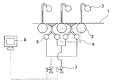
- FIG. 2 is a detailed view of the cooling device of the present invention.
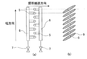
- FIG. 3 is a diagram for explaining a collision pattern of the spray cooling device with the piping system and the flat spray steel strip.
- FIG. 4 is a diagram showing injection as two-system cooling water in the bottom surface cooling device.
- FIG. 5 is a view showing injection as one-system cooling water in the lower surface cooling device.
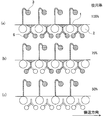
- FIG. 6 is a diagram showing a pattern for changing the injection rate of the cooling water.
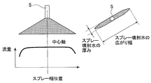
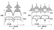
- FIG. 7 is a view showing a flow rate distribution of a general flat spray nozzle.
- FIG. 8 is a diagram showing injection as one-system cooling water in the lower surface cooling device.
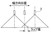
- FIG. 9 is a view for explaining the position of the spray end in the width direction.
- FIG. 10 is a view showing a state where the spray end portions slightly wrap around each other.
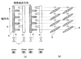
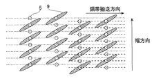
- FIG. 11 is a diagram illustrating a state in which the two bottom surface cooling devices are paired and the nozzle installation position in the width direction is shifted by 1 ⁇ 2 of the nozzle mounting pitch between adjacent pairs.
- FIG. 12 is a diagram showing the spray pattern in FIG. 11 (two-line injection).
- FIG. 13 is a diagram showing the spray pattern in FIG. 11 (single system injection).
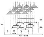
- FIG. 14 is a schematic diagram of the flow rate distribution in FIG. 13 (single system injection).
- FIG. 15 is a diagram showing another embodiment of the present invention.
- FIG. 16 is a diagram showing another embodiment of the present invention.
- FIG. 15 is a diagram showing another embodiment of the present invention.
- FIG. 17 is a view showing a detailed arrangement of the lower surface nozzles in the embodiment of the present invention.
- FIG. 18 is a diagram showing a detailed arrangement of the lower surface nozzles in the embodiment of the present invention.
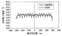
- FIG. 19 is a diagram showing the temperature distribution of the present invention example 2 and the comparative example.
- FIG. 1 is a diagram illustrating an embodiment relating to a cooling device in a case where the present invention is applied to lower surface cooling of a hot-rolled steel strip at a runout table.
- the hot-rolled steel strip is rolled to a predetermined thickness by a rough rolling mill group 31 and a finish rolling mill group 32 after a slab (for example, 250 mm thick), which is a raw material, is heated by a heating furnace 30 (for example, 1200 ° C.). After that, it is cooled by the cooling device 33 of the present invention and wound up by the coiler 34.
- a heating furnace 30 for example, 1200 ° C.
- FIG. 2 shows details of the cooling device 33 of the present invention in FIG.
- a table roller 2 that conveys the steel strip 1
- a pipe laminar nozzle 3 that cools the upper surface of the steel strip
- a spray cooling device 4 that cools the lower surface of the steel strip are installed between the table rollers 2.
- the spray nozzle 5 a flat spray nozzle sprayed in a fan shape is generally attached.
- the spray cooling device 4 is composed of a header 6 and an injection valve 7 that form a pair of two systems, and the injection valve 7 can individually set injection / stop of cooling water by a control mechanism 8. Yes.
- FIG. 3 (a) illustrates the piping system of the spray cooling device 4 installed between one table roller.
- the spray nozzles 5 are arranged at a predetermined pitch in a row in the width direction of the steel strip, but two cooling headers 6 are arranged so that the spray nozzles 5 adjacent to each other in the width direction can supply cooling water from different piping systems.
- Each is provided with an injection valve 7 so that cooling water can be injected / stopped individually.
- FIG. 3 (b) shows the pattern when the flat spray at that time collides with the steel strip.
- the width direction position of the width end of the spray water 9 is 0 to 30 mm on the opposite side of the nozzle center axis of the adjacent nozzle in the width direction of the spray nozzle 5 to which the spray water 9 is sprayed. Arrange to come.
- the injection rate is 50% when jetting the pipe laminar nozzle 3 on the upper surface
- the spray rate when spraying the two sets of the spray cooling device 4 of the present invention on the lower surface is 50%.
- the upper and lower total injection rate in this case is 100%, in the state where the upper surface pipe laminar nozzle 3 is injected as shown in FIG. 6, when the lower surface spray nozzle 4 is injected two systems (FIG. 4 and FIG. 6A)
- the cooling water injection rate is 100% (upper surface: 50%, lower surface: 50%)
- the water cooling speed is the fastest
- one spray nozzle 4 on the lower surface is injected (FIGS. 5 and 6B).
- the cooling water injection rate is 75% (upper surface: 50%, lower surface: 25%), the water cooling rate is medium, and when the lower surface spray nozzle 4 is not injected (FIG. 6C), the cooling water injection rate is 50% (Top: 50%, bottom : 0%) and most of the water-cooling speed, it is possible to slow down.
- the feature of this method is that the amount of cooling water can be set only by injection / stop of the cooling water by the injection valve 7 and the control mechanism 8. For this reason, since injection / stop of cooling water can be handled by a general valve, the amount of cooling water can be set very easily. Further, by increasing the opening / closing speed of the injection valve 7, the cooling water density can be set very quickly. For example, when a high-speed on-off valve called a cylinder valve is employed, switching is completed in an operation time of 1 second or less. Compared to this, when performing a general flow density adjustment, it is necessary to install a flow adjustment valve, but in order to finely adjust the valve opening while measuring with a flow meter, a general flow adjustment valve is used.
- FIG. 7 shows the flow rate distribution of a general flat spray nozzle, but the flow rate sprayed from the spray tends to decrease at the end in the width direction. Therefore, when the water supply of the spray nozzle 5 on the lower surface is one system, it is preferable that the water supply piping between the adjacent table rollers jets the cooling water from an alternate position.
- FIG. 9A is a schematic diagram of the flow rate distribution when only one system of cooling water is injected with the arrangement as shown in FIG.
- the position in the width direction of the spray end coincides with the spray between the different table roller rollers, so the flow rate distribution synthesized in the transport direction is the position corresponding to the spray end.
- the flow rate is reduced. Therefore, as shown in FIG. 5 and FIG. 9B, the positions of the spray ends are dispersed and synthesized in the transport direction by alternating the water supply positions of the water supply pipes with the headers in the transport direction as in the present invention.
- the flow distribution can be made uniform.
- the end width direction position when the cooling water sprayed from the spray nozzle collides with the steel strip is preferably matched with the center axis position of the adjacent nozzle, but with respect to the center axis of the adjacent nozzle. You may arrange
- FIG. 11 two sets of lower surface cooling devices installed between the table rollers in the conveying direction are set as one pair, and the nozzle installation position in the width direction is shifted by 1/2 of the nozzle mounting pitch between adjacent pairs. And more preferred.
- the spray pattern in such an arrangement is shown in FIG. 12 (two-line injection) and FIG. 13 (one-line injection), but the end position in the steel strip width direction of the spray is different from each of the four table rollers. I can do it.
- FIG. 14 shows a schematic diagram of the flow rate distribution when one system injection is performed in such an arrangement. Compared with the nozzle arrangement described in FIG. 5, the position in the width direction of the spray end is further dispersed. The flow distribution in the width direction becomes more uniform.
- FIG. 15 shows another embodiment of the present invention in which upper surface cooling is entangled with lower surface cooling.
- a plurality of pipe laminar nozzles 3 on the upper surface are arranged so that cooling water falls between the upper surface of the table roller and the table roller, and the spray nozzle 4 on the lower surface is an example in which the cooling device of the present invention is arranged.
- the upper surface pipe laminar nozzle is individually provided with an injection valve 7 (not shown) so that cooling water can be injected / stopped independently.
- the injection rate of the cooling water is 100%, the upper surface is 50% and the lower surface is 50%. Therefore, the injection rate is 25% [FIG. 15 (d)] (upper surface only by injection / stop of each header). : 25% (only the pipe laminar nozzle falling on the table roller 2 is sprayed), bottom surface: 0% (no spray)), spray rate 50% [Fig. 15 (c)] (top surface: 25% (on the table roller 2) (Only the falling pipe laminar nozzle is sprayed), lower surface: 25% (single system spray)), injection rate 75% [Fig.
- the hatching in the figure indicates the supply of cooling water.
- the cooling water density is 1000 L / min ⁇ m 2 when both the header where the cooling water falls on the table roller and between the table rollers is injected on the upper surface, and the cooling water is supplied from the two lower surfaces.
- Table 1 shows the water amount density per one side obtained by averaging the upper surface and the lower surface obtained by changing the jet rate of the upper surface / lower surface when the cooling water amount density is 700 L / min ⁇ m 2 .
- Maximum 850 L / min. m 2 to a minimum of 175 L / min. m 2 and about 5 times the amount of cooling water changes can be adjusted only by the injection pattern of 8 stages.
- the spray nozzle 5 is described as a flat spray nozzle, it may be an elliptical or rectangular spray.
- the ratio between the thickness of the spray jet water and the spread width should be as small as possible. It is preferable that at least the thickness is smaller than the nozzle pitch in the width direction, and the ratio between the thickness and the spread width is 0.4 or less.
- FIG. 16 shows another embodiment relating to the piping system and the control mechanism 8.
- a plurality of pipes of the header 6 used when only one system is injected to each lower surface cooling device 4 are collected, and the injection / stop of cooling water is controlled by the control mechanism 8 as one injection valve 7.
- the control mechanism 8 controls the injection / stop of cooling water as one injection valve 7.
- the number of injection valves 7 can be reduced, and the number of control points and the number of cables in the control mechanism 8 can be reduced, leading to a reduction in equipment costs.
- a slab having a thickness of 250 mm was heated to 1200 ° C. in a heating furnace 30, and then a thickness of 3.2 mm by a rough rolling mill group 31 and a finishing rolling mill group 32.
- the steel sheet was rolled to a plate width of 1200 mm, cooled by the cooling device 33, and taken up by the coiler 34.
- the temperature after the end of rolling and after the end of cooling was measured with a radiation thermometer 35.
- the temperature after the end of rolling was 850 ° C.
- the temperature after the end of cooling was 550 ° C.
- the steel strip passing speed during cooling was 550 mpm.
- the cooling device 33 has the pipe laminar nozzle 3 on the upper surface and the spray cooling 4 of the present invention on the lower surface.
- Flow density of injected per unit area is a top cooling 1000L / min ⁇ m 2
- the lower surface cooling becomes when two systems injection per one place between table rollers and 1000L / min ⁇ m 2.
- the spray nozzle pitch P is 80 mm
- the distance between the table rollers is 420 mm
- the spray twist angle ⁇ is 42 °.
- a spray nozzle is selected such that the adjacent nozzle center axis and the position in the width direction of the end of the spray water coincide.
- the distance between the nozzle and the steel strip was 140 mm, the table roller diameter was 350 mm, and the spray spread angle was 90 °.
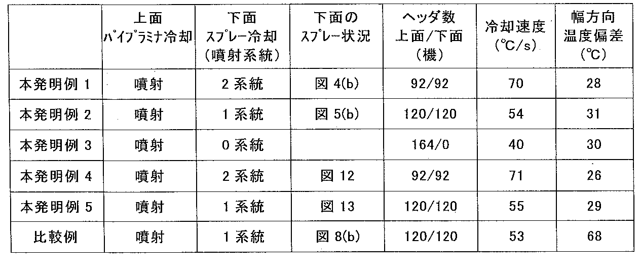
- Table 2 shows the results of cooling in the inventive example and the comparative example.
- one system (width direction 1 group) of the upper surface pipe laminator 3 of FIG. 2 and 1 system (width direction 1 group) of the lower surface spline nozzle 5 are collectively called a cooling header.
- Example 1 of the present invention two systems were injected on the lower surface as shown in FIG. 4, and 92 cooling headers on each of the upper and lower surfaces were injected.
- the cooling rate at this time was 70 ° C./s.
- Example 2 of the present invention as shown in FIG. 5, one line of cooling is performed on the bottom surface, and 120 cooling headers on each of the top and bottom surfaces are sprayed.
- the cooling rate at this time was 54 ° C./s.
- Example 3 of the present invention 164 cooling headers were injected only on the upper surface without performing the lower surface cooling injection.
- the cooling rate at this time was 40 ° C./s.
- the cooling rate can be adjusted from 40 ° C./s to 70 ° C./s. Further, the temperature deviation in the width direction after cooling was as good as around 30 ° C.
- the cooling rate can be easily adjusted during cooling after finish rolling in the hot-rolled steel strip production line.
- the present invention it has become possible to contribute to the production of a wide variety of hot-rolled steel strips.
- Examples 4 and 5 of the present invention are the results of the piping configuration of FIG. Note that the nozzles in the width direction of the nozzles were shifted by a half of the mounting pitch in the width direction between adjacent pairs of nozzles.
- Example 4 of the present invention as shown in FIG. 12, two systems are injected on the lower surface, and 92 cooling headers on each of the upper and lower surfaces are injected.
- the cooling rate at this time was 71 ° C./s, which was almost the same as that of Example 1 of the present invention.
- the temperature deviation in the width direction after cooling was 26 ° C., and the temperature deviation was slightly smaller than that of Example 1 of the present invention at which the cooling rate was almost the same. This is a result of further dispersing the water amount distribution after spray injection by shifting the mounting pitch in the width direction by 1 ⁇ 2 for some spray nozzles.
- Example 5 of the present invention as shown in FIG. 13, one system is injected on the lower surface, and 120 cooling headers on each of the upper and lower surfaces are injected.
- the cooling rate at this time was 55 ° C./s, which was equivalent to Example 2 of the present invention.
- the temperature deviation in the width direction after cooling was 29 ° C., and the temperature deviation was slightly smaller than Example 2 of the present invention in which the cooling rate was almost the same. This is a result of further dispersing the water amount distribution after spray injection by shifting the mounting pitch in the width direction by 1 ⁇ 2 for some spray nozzles.
- the lower surface cooling is performed by one system injection, but the nozzle arrangement between the adjacent table rollers coincides with the steel strip conveyance direction, and each of the upper surface / lower surface 120 cooling headers are injected.
- the cooling rate at this time was 53 ° C./s, which was the same as Example 2 of the present invention, but the temperature deviation in the width direction was as large as 68 ° C.
- FIG. 19 shows temperature distributions of the inventive example 2 and the comparative example, which have substantially the same cooling rate.
- Example 2 of the present invention there was a slight temperature drop at the end of the plate, but it was almost uniform at the center of the plate width, whereas in the comparative example, a high and low temperature region was generated at a pitch of about 80 mm. This seems to be due to the fact that the flow distribution after spray injection could not be dispersed in the width direction.
Landscapes
- Engineering & Computer Science (AREA)
- Mechanical Engineering (AREA)
- Heat Treatment Of Strip Materials And Filament Materials (AREA)
- Heat Treatments In General, Especially Conveying And Cooling (AREA)
- Nozzles (AREA)
Abstract
Description
冷却速度を大きくする場合は、1組の冷却ヘッダに2系統の供給配管から冷却水を供給して1組の冷却ヘッダの全てのスプレーノズルから冷却水を噴射し、冷却速度を小さくする場合は、1組の冷却ヘッダに1系統の供給配管から冷却水を供給して1組の冷却ヘッダでの幅方向に取り付けられたスプレーノズルのうち1本おきに冷却水を噴射する熱延鋼帯の冷却方法。
前記冷却ヘッダでは、冷却水の供給を2系統を1組として行い、冷却水の2系統の供給配管には冷却水の噴射または停止を独立して可能なように噴射弁を取り付けられていると共に、幅方向に隣り合うスプレーノズルはそれぞれ前記2系統の供給配管のうちの異なる系統の供給配管に接続された配管系統を持ち、
冷却速度を大きくする場合は、1組の冷却ヘッダに2系統の供給配管から冷却水を供給して1組の冷却ヘッダの全てのスプレーノズルから冷却水を噴射し、冷却速度を小さくする場合は、1組の冷却ヘッダに1系統の供給配管から冷却水を供給して1組の冷却ヘッダでの幅方向に取り付けられたスプレーノズルのうち1本おきに冷却水を噴射することを可能とする制御機構を持つ熱延鋼帯の冷却装置。

2 テーブルローラ
3 パイプラミナーノズル
4 スプレー冷却装置
5 スプレーノズル
6 冷却ヘッダ
7 噴射弁
8 噴射弁制御機構
9 スプレー水
30 加熱炉
31 粗圧延機群
32 仕上げ圧延機群
33 ランアウトテーブル冷却装置
34 コイラー
35 放射温度計
Claims (12)
- 幅方向に複数のスプレーノズルを配置した冷却ヘッダを鋼帯搬送方向に複数配置した冷却装置であって、前記冷却ヘッダでは、冷却水の供給を2系統を1組として行い、冷却水の2系統の供給配管には冷却水の噴射または停止を独立して可能なように弁が取り付けられていると共に、幅方向に隣り合うスプレーノズルはそれぞれ前記2系統の供給配管のうちの異なる系統の供給配管に接続している配管系統を有する冷却装置を準備し、
冷却速度を大きくする場合は、1組の冷却ヘッダに2系統の供給配管から冷却水を供給して1組の冷却ヘッダの全てのスプレーノズルから冷却水を噴射し、冷却速度を小さくする場合は、1組の冷却ヘッダに1系統の供給配管から冷却水を供給して1組の冷却ヘッダでの幅方向に取り付けられたスプレーノズルのうち1本おきに冷却水を噴射する熱延鋼帯の冷却方法。 - 冷却ヘッダは鋼帯搬送方向において2組をペアとし、ペアの冷却ヘッダに取り付けるスプレーノズルは鋼帯搬送方向の設置位置が一致すると共に、それぞれのペアにおいて2系統ある供給配管のうちの1系統の供給配管からの冷却水を噴射する場合は、2組のペアのそれぞれのスプレーノズルは幅方向で交互になる位置から冷却水を噴射する請求項1に記載の熱延鋼帯の冷却方法。
- スプレーノズルは、矩形若しくは楕円状の噴射パターンを持ち、冷却水の供給を2系統から実施する場合には、冷却水が鋼帯に衝突するときにスプレー衝突部の端部位置は隣のノズル中心軸に対して、冷却水を噴射したノズルと逆側に0~30mmだけずれた位置に衝突する配置とする請求項1または2に記載の熱延鋼帯の冷却方法。
- 冷却ヘッダは鋼帯搬送方向において2組をペアとし、ペアでは幅方向に取り付けるスプレーノズルの鋼帯搬送方向の設置位置を一致させると共に、隣り合うペアの冷却ヘッダは幅方向のノズル取付け位置をノズル取付けピッチの1/2だけ幅方向にずらす請求項1~3のいずれかに記載の熱延鋼帯の冷却方法。
- 鋼帯上面と下面とで異なる冷却水量密度とし、鋼帯上面および下面のぞれぞれの冷却ヘッダにおいて、個別に冷却水の供給配管本数を変更する請求項1~4のいずれかに記載の熱延鋼帯の冷却方法。
- 鋼帯の下面冷却に適用する請求項1~5のいずれかに記載の熱延鋼帯の冷却方法。
- 幅方向に複数のスプレーノズルを配置した冷却ヘッダを鋼帯搬送方向に複数配置した冷却装置であって、
前記冷却ヘッダでは、冷却水の供給を2系統を1組として行い、冷却水の2系統の供給配管には冷却水の噴射または停止を独立して可能なように噴射弁を取り付けられていると共に、幅方向に隣り合うスプレーノズルはそれぞれ前記2系統の供給配管のうちの異なる系統の供給配管に接続された配管系統を持ち、
冷却速度を大きくする場合は、1組の冷却ヘッダに2系統の供給配管から冷却水を供給して1組の冷却ヘッダの全てのスプレーノズルから冷却水を噴射し、冷却速度を小さくする場合は、1組の冷却ヘッダに1系統の供給配管から冷却水を供給して1組の冷却ヘッダでの幅方向に取り付けられたスプレーノズルのうち1本おきに冷却水を噴射することを可能とする制御機構を持つ熱延鋼帯の冷却装置。 - 冷却ヘッダは鋼帯搬送方向において2組をペアとし、ペアの冷却ヘッダに取り付けるスプレーノズルは鋼板搬送方向の設置位置が一致すると共に、それぞれのペアにおいて2系統ある供給配管の1系統の供給配管からの冷却水を噴射する場合は、2組のペアのそれぞれのスプレーノズルは幅方向で交互になる位置から冷却水を噴射するように噴射弁を開閉可能な制御機能をもつ請求項7に記載の熱延鋼帯の冷却装置。
- スプレーノズルは、矩形若しくは楕円状の噴射パターンを持ち、冷却水が鋼帯に衝突するときにスプレー衝突部の端部位置は隣のノズル中心軸に対して、冷却水を噴射したノズルと逆側に0~30mmだけずれた配置とした請求項7または8に記載の熱延鋼帯の冷却装置。
- 冷却ヘッダは鋼帯搬送方向において2組をペアとし、ペアでは幅方向に取り付けるスプレーノズルの鋼帯搬送方向の設置位置を一致させると共に、隣り合うペアの冷却ヘッダは幅方向のノズル取り付け位置をノズル取付けピッチの1/2だけ幅方向にずらした請求項7~9のいずれかに記載の熱延鋼帯の冷却装置。
- 2系統冷却水を供給した場合に、鋼帯上面と下面とで異なる冷却水量密度で噴射可能とし、鋼帯上面および下面のぞれぞれの冷却ヘッダにおいて、個別に冷却水の給水系統数を変更するために噴射弁を開閉可能な制御機能を持つ請求項7~10のいずれかに記載の熱延鋼帯の冷却装置。
- 鋼帯の下面冷却に適用する請求項7~11のいずれかに記載の熱延鋼帯の冷却装置。
Priority Applications (4)
| Application Number | Priority Date | Filing Date | Title |
|---|---|---|---|
| KR1020157011419A KR101631044B1 (ko) | 2012-12-25 | 2013-11-27 | 열연 강대의 냉각 방법 및 냉각 장치 |
| EP13867229.0A EP2939751B1 (en) | 2012-12-25 | 2013-11-27 | Cooling method and cooling device for hot-rolled steel strip |
| US14/655,104 US9833822B2 (en) | 2012-12-25 | 2013-11-27 | Method and apparatus for cooling hot-rolled steel strip |
| CN201380067906.9A CN104884182B (zh) | 2012-12-25 | 2013-11-27 | 热轧钢带的冷却方法及冷却装置 |
Applications Claiming Priority (2)
| Application Number | Priority Date | Filing Date | Title |
|---|---|---|---|
| JP2012280418A JP5825250B2 (ja) | 2012-12-25 | 2012-12-25 | 熱延鋼帯の冷却方法および冷却装置 |
| JP2012-280418 | 2012-12-25 |
Publications (1)
| Publication Number | Publication Date |
|---|---|
| WO2014103164A1 true WO2014103164A1 (ja) | 2014-07-03 |
Family
ID=51020293
Family Applications (1)
| Application Number | Title | Priority Date | Filing Date |
|---|---|---|---|
| PCT/JP2013/006952 Ceased WO2014103164A1 (ja) | 2012-12-25 | 2013-11-27 | 熱延鋼帯の冷却方法および冷却装置 |
Country Status (7)
| Country | Link |
|---|---|
| US (1) | US9833822B2 (ja) |
| EP (1) | EP2939751B1 (ja) |
| JP (1) | JP5825250B2 (ja) |
| KR (1) | KR101631044B1 (ja) |
| CN (1) | CN104884182B (ja) |
| TW (1) | TWI553124B (ja) |
| WO (1) | WO2014103164A1 (ja) |
Cited By (2)
| Publication number | Priority date | Publication date | Assignee | Title |
|---|---|---|---|---|
| CN115532855A (zh) * | 2022-10-10 | 2022-12-30 | 江苏东方成套设备制造集团有限公司 | 一种连续穿水冷却装置 |
| CN116984401A (zh) * | 2023-08-09 | 2023-11-03 | 湖南华菱涟钢特种新材料有限公司 | 一种减少带钢边部液体残留的控制方法 |
Families Citing this family (10)
| Publication number | Priority date | Publication date | Assignee | Title |
|---|---|---|---|---|
| WO2018073973A1 (ja) * | 2016-10-19 | 2018-04-26 | 新日鐵住金株式会社 | 熱延鋼板の冷却方法及び冷却装置 |
| EP3603833B1 (en) * | 2017-03-31 | 2023-11-29 | Nippon Steel Corporation | Device and method for cooling hot-rolled steel sheet |
| CN115156314A (zh) * | 2017-12-20 | 2022-10-11 | 杰富意钢铁株式会社 | 厚钢板的冷却装置及冷却方法以及厚钢板的制造设备及制造方法 |
| CN109732050B (zh) * | 2019-03-06 | 2023-11-03 | 南京钢铁股份有限公司 | 一种连铸机切前辊道冷却系统 |
| DE102019106730A1 (de) * | 2019-03-18 | 2020-01-02 | Primetals Technologies Austria GmbH | Kühlung von flachem Walzgut ohne Nachlaufen des Headers |
| JP7131707B2 (ja) * | 2019-08-02 | 2022-09-06 | Jfeスチール株式会社 | 連続鋳造鋳片の二次冷却装置及び二次冷却方法 |
| JP7052931B2 (ja) * | 2019-10-29 | 2022-04-12 | Jfeスチール株式会社 | 連続鋳造鋳片の二次冷却方法 |
| CN113000608B (zh) * | 2021-02-05 | 2023-04-11 | 首钢集团有限公司 | 一种轧机工作辊的冷却水横向流量分布获取方法及装置 |
| CN115679054B (zh) * | 2021-07-29 | 2025-02-18 | 宝山钢铁股份有限公司 | 集约化热卷连续热处理的全气雾式、雾水混合式冷却装置 |
| CN114433646B (zh) * | 2022-01-21 | 2023-06-23 | 临沂大学 | 一种用于热轧带钢轧后冷却系统的水配管装置及冷却系统 |
Citations (4)
| Publication number | Priority date | Publication date | Assignee | Title |
|---|---|---|---|---|
| JPS5947010A (ja) | 1982-09-11 | 1984-03-16 | Kobe Steel Ltd | 鋼板下面冷却装置 |
| JPH0239604Y2 (ja) * | 1984-04-04 | 1990-10-24 | ||
| JPH07214136A (ja) * | 1994-01-31 | 1995-08-15 | Kawasaki Steel Corp | 高温金属板の下面冷却装置 |
| JP2006035311A (ja) * | 2004-06-23 | 2006-02-09 | Nippon Steel Corp | 厚鋼板の冷却装置 |
Family Cites Families (23)
| Publication number | Priority date | Publication date | Assignee | Title |
|---|---|---|---|---|
| JPS5890313A (ja) * | 1981-11-20 | 1983-05-30 | Nippon Steel Corp | 鋼板の冷却装置 |
| JPS6018218A (ja) | 1983-07-12 | 1985-01-30 | Ishikawajima Harima Heavy Ind Co Ltd | 鋼板の冷却装置 |
| US4932232A (en) * | 1988-05-20 | 1990-06-12 | Alcan Aluminum Corporation | Methods of detecting and correcting spray header malfunctions |
| JPH06166413A (ja) | 1991-03-05 | 1994-06-14 | Honda Motor Co Ltd | コンベアチェーン |
| JPH05123737A (ja) | 1991-11-05 | 1993-05-21 | Sumitomo Metal Ind Ltd | 高温鋼板の上面冷却方法 |
| JPH09253730A (ja) | 1996-03-19 | 1997-09-30 | Kawasaki Steel Corp | 熱延鋼帯の冷却装置 |
| JP3747546B2 (ja) | 1997-01-17 | 2006-02-22 | Jfeスチール株式会社 | 高温鋼板の冷却方法および装置 |
| DE19850253A1 (de) * | 1998-10-31 | 2000-05-04 | Schloemann Siemag Ag | Verfahren und System zur Regelung von Kühlstrecken |
| WO2004014577A1 (ja) * | 2002-08-08 | 2004-02-19 | Jfe Steel Corporation | 熱延鋼帯の冷却装置、熱延鋼帯の製造方法および熱延鋼帯の製造ライン |
| BRPI0519986B1 (pt) | 2005-06-23 | 2019-06-04 | Nippon Steel & Sumitomo Metal Corporation | Aparelho de resfriamento de chapas de aço de bitola grossa |
| US8318080B2 (en) | 2005-11-11 | 2012-11-27 | Jfe Steel Corporation | Device and method for cooling hot strip |
| US8231826B2 (en) * | 2006-03-03 | 2012-07-31 | Jfe Steel Corporation | Hot-strip cooling device and cooling method |
| US8353191B2 (en) * | 2006-07-27 | 2013-01-15 | Jfe Steel Corporation | Cooling device and cooling method for hot strip |
| BRPI0702829B1 (pt) * | 2006-09-12 | 2020-02-18 | Nippon Steel Corporation | Método de instalar e configurar bocais de resfriamento por vaporização e aparelho de resfriamento de placas de aço quente |
| DE102006043567A1 (de) | 2006-09-16 | 2008-03-27 | Sms Demag Ag | Spritzbalken einer hydraulischen Entzunderungsanlage und Verfahren zum Betreiben eines solchen Spritzbalkens |
| JP4449991B2 (ja) * | 2007-02-26 | 2010-04-14 | Jfeスチール株式会社 | 熱延鋼帯の冷却装置及び方法 |
| DE102007046279A1 (de) * | 2007-09-27 | 2009-04-09 | Siemens Ag | Betriebsverfahren für eine Kühlstrecke mit zentralisierter Erfassung von Ventilcharakteristiken und hiermit korrespondierende Gegenstände |
| JP4924475B2 (ja) | 2008-02-27 | 2012-04-25 | Jfeスチール株式会社 | ホットレベラおよび二重管 |
| PT2100673E (pt) * | 2008-03-14 | 2011-04-01 | Arcelormittal France | Processo e dispositivo de sopragem de gás sobre uma banda em movimento contínuo |
| CN101456040A (zh) | 2008-12-29 | 2009-06-17 | 中冶南方工程技术有限公司 | 中厚钢板控制冷却侧喷系统 |
| CN102548680B (zh) * | 2009-06-30 | 2015-04-01 | 新日铁住金株式会社 | 热轧钢板的冷却装置、冷却方法、制造装置及制造方法 |
| JP4678448B2 (ja) * | 2009-07-15 | 2011-04-27 | 住友金属工業株式会社 | 熱延鋼板の製造装置、及び鋼板の製造方法 |
| JP5947010B2 (ja) | 2011-09-15 | 2016-07-06 | 株式会社ディスコ | 分割装置 |
-
2012
- 2012-12-25 JP JP2012280418A patent/JP5825250B2/ja active Active
-
2013
- 2013-11-27 WO PCT/JP2013/006952 patent/WO2014103164A1/ja not_active Ceased
- 2013-11-27 KR KR1020157011419A patent/KR101631044B1/ko active Active
- 2013-11-27 CN CN201380067906.9A patent/CN104884182B/zh active Active
- 2013-11-27 US US14/655,104 patent/US9833822B2/en active Active
- 2013-11-27 EP EP13867229.0A patent/EP2939751B1/en active Active
- 2013-12-23 TW TW102147733A patent/TWI553124B/zh active
Patent Citations (4)
| Publication number | Priority date | Publication date | Assignee | Title |
|---|---|---|---|---|
| JPS5947010A (ja) | 1982-09-11 | 1984-03-16 | Kobe Steel Ltd | 鋼板下面冷却装置 |
| JPH0239604Y2 (ja) * | 1984-04-04 | 1990-10-24 | ||
| JPH07214136A (ja) * | 1994-01-31 | 1995-08-15 | Kawasaki Steel Corp | 高温金属板の下面冷却装置 |
| JP2006035311A (ja) * | 2004-06-23 | 2006-02-09 | Nippon Steel Corp | 厚鋼板の冷却装置 |
Non-Patent Citations (1)
| Title |
|---|
| See also references of EP2939751A4 * |
Cited By (3)
| Publication number | Priority date | Publication date | Assignee | Title |
|---|---|---|---|---|
| CN115532855A (zh) * | 2022-10-10 | 2022-12-30 | 江苏东方成套设备制造集团有限公司 | 一种连续穿水冷却装置 |
| CN115532855B (zh) * | 2022-10-10 | 2024-01-09 | 江苏东方成套设备制造集团有限公司 | 一种连续穿水冷却装置 |
| CN116984401A (zh) * | 2023-08-09 | 2023-11-03 | 湖南华菱涟钢特种新材料有限公司 | 一种减少带钢边部液体残留的控制方法 |
Also Published As
| Publication number | Publication date |
|---|---|
| EP2939751A4 (en) | 2016-01-27 |
| US9833822B2 (en) | 2017-12-05 |
| JP5825250B2 (ja) | 2015-12-02 |
| KR101631044B1 (ko) | 2016-06-15 |
| EP2939751A1 (en) | 2015-11-04 |
| JP2014124634A (ja) | 2014-07-07 |
| US20150321234A1 (en) | 2015-11-12 |
| KR20150063539A (ko) | 2015-06-09 |
| TWI553124B (zh) | 2016-10-11 |
| CN104884182A (zh) | 2015-09-02 |
| TW201432056A (zh) | 2014-08-16 |
| CN104884182B (zh) | 2017-06-20 |
| EP2939751B1 (en) | 2017-06-07 |
Similar Documents
| Publication | Publication Date | Title |
|---|---|---|
| JP5825250B2 (ja) | 熱延鋼帯の冷却方法および冷却装置 | |
| KR101162070B1 (ko) | 열연 강판의 냉각 장치 | |
| KR101026972B1 (ko) | 열연강대의 냉각 방법 | |
| TWI731415B (zh) | 熱軋鋼板之冷卻裝置及熱軋鋼板之冷卻方法 | |
| WO2012039270A1 (ja) | 熱延鋼帯の冷却装置 | |
| JP6569843B1 (ja) | 厚鋼板の冷却装置および冷却方法ならびに厚鋼板の製造設備および製造方法 | |
| JP2011516274A (ja) | 制御冷却のための方法および装置 | |
| KR100973692B1 (ko) | 강판의 열간압연 설비 및 열간압연 방법 | |
| JP4029865B2 (ja) | 熱延鋼板の製造設備及び熱延鋼板の製造方法 | |
| JP4924538B2 (ja) | 熱延鋼板の製造装置及び製造方法 | |
| JP4337157B2 (ja) | 鋼板の冷却方法およびその装置 | |
| JP2020513480A (ja) | 金属ストリップの連続処理ラインの急速冷却方法及び急速冷却部 | |
| JP5663848B2 (ja) | 熱延鋼板の冷却装置及びその動作制御方法 | |
| JP2011011222A (ja) | 熱延鋼板の冷却装置、熱延鋼板の製造装置及び製造方法 | |
| CN115679053A (zh) | 用于集约化热轧卷连续热处理的气雾冷却装置及其方法 |
Legal Events
| Date | Code | Title | Description |
|---|---|---|---|
| 121 | Ep: the epo has been informed by wipo that ep was designated in this application |
Ref document number: 13867229 Country of ref document: EP Kind code of ref document: A1 |
|
| ENP | Entry into the national phase |
Ref document number: 20157011419 Country of ref document: KR Kind code of ref document: A |
|
| WWE | Wipo information: entry into national phase |
Ref document number: 14655104 Country of ref document: US |
|
| NENP | Non-entry into the national phase |
Ref country code: DE |
|
| REEP | Request for entry into the european phase |
Ref document number: 2013867229 Country of ref document: EP |
|
| WWE | Wipo information: entry into national phase |
Ref document number: 2013867229 Country of ref document: EP |