WO2014103632A1 - Structure pour une mâchoire en résine - Google Patents
Structure pour une mâchoire en résine Download PDFInfo
- Publication number
- WO2014103632A1 WO2014103632A1 PCT/JP2013/082539 JP2013082539W WO2014103632A1 WO 2014103632 A1 WO2014103632 A1 WO 2014103632A1 JP 2013082539 W JP2013082539 W JP 2013082539W WO 2014103632 A1 WO2014103632 A1 WO 2014103632A1
- Authority
- WO
- WIPO (PCT)
- Prior art keywords
- claw
- locking
- locking hole
- resin
- position restricting
- Prior art date
- Legal status (The legal status is an assumption and is not a legal conclusion. Google has not performed a legal analysis and makes no representation as to the accuracy of the status listed.)
- Ceased
Links
Images



Classifications
-
- F—MECHANICAL ENGINEERING; LIGHTING; HEATING; WEAPONS; BLASTING
- F16—ENGINEERING ELEMENTS AND UNITS; GENERAL MEASURES FOR PRODUCING AND MAINTAINING EFFECTIVE FUNCTIONING OF MACHINES OR INSTALLATIONS; THERMAL INSULATION IN GENERAL
- F16B—DEVICES FOR FASTENING OR SECURING CONSTRUCTIONAL ELEMENTS OR MACHINE PARTS TOGETHER, e.g. NAILS, BOLTS, CIRCLIPS, CLAMPS, CLIPS OR WEDGES; JOINTS OR JOINTING
- F16B5/00—Joining sheets or plates, e.g. panels, to one another or to strips or bars parallel to them
- F16B5/06—Joining sheets or plates, e.g. panels, to one another or to strips or bars parallel to them by means of clamps or clips
- F16B5/0607—Joining sheets or plates, e.g. panels, to one another or to strips or bars parallel to them by means of clamps or clips joining sheets or plates to each other
- F16B5/0621—Joining sheets or plates, e.g. panels, to one another or to strips or bars parallel to them by means of clamps or clips joining sheets or plates to each other in parallel relationship
- F16B5/065—Joining sheets or plates, e.g. panels, to one another or to strips or bars parallel to them by means of clamps or clips joining sheets or plates to each other in parallel relationship the plates being one on top of the other and distanced from each other, e.g. by using protrusions to keep contact and distance
-
- B—PERFORMING OPERATIONS; TRANSPORTING
- B60—VEHICLES IN GENERAL
- B60R—VEHICLES, VEHICLE FITTINGS, OR VEHICLE PARTS, NOT OTHERWISE PROVIDED FOR
- B60R13/00—Elements for body-finishing, identifying, or decorating; Arrangements or adaptations for advertising purposes
- B60R13/02—Internal Trim mouldings ; Internal Ledges; Wall liners for passenger compartments; Roof liners
-
- F—MECHANICAL ENGINEERING; LIGHTING; HEATING; WEAPONS; BLASTING
- F16—ENGINEERING ELEMENTS AND UNITS; GENERAL MEASURES FOR PRODUCING AND MAINTAINING EFFECTIVE FUNCTIONING OF MACHINES OR INSTALLATIONS; THERMAL INSULATION IN GENERAL
- F16B—DEVICES FOR FASTENING OR SECURING CONSTRUCTIONAL ELEMENTS OR MACHINE PARTS TOGETHER, e.g. NAILS, BOLTS, CIRCLIPS, CLAMPS, CLIPS OR WEDGES; JOINTS OR JOINTING
- F16B5/00—Joining sheets or plates, e.g. panels, to one another or to strips or bars parallel to them
- F16B5/06—Joining sheets or plates, e.g. panels, to one another or to strips or bars parallel to them by means of clamps or clips
- F16B5/0607—Joining sheets or plates, e.g. panels, to one another or to strips or bars parallel to them by means of clamps or clips joining sheets or plates to each other
- F16B5/0621—Joining sheets or plates, e.g. panels, to one another or to strips or bars parallel to them by means of clamps or clips joining sheets or plates to each other in parallel relationship
- F16B5/0664—Joining sheets or plates, e.g. panels, to one another or to strips or bars parallel to them by means of clamps or clips joining sheets or plates to each other in parallel relationship at least one of the sheets or plates having integrally formed or integrally connected snap-in-features
Definitions
- This invention relates to a resin nail structure.
- counterpart parts For vehicles such as automobiles, a large number of resin parts are used inside and outside the passenger compartment. Structures for attaching such resin parts to a vehicle body or other parts (hereinafter referred to as counterpart parts) are roughly divided into two types, screw fixing and claw fixing.
- the claw fixing is further formed integrally with the resin part with the same material as the resin part and the one with a separate claw structure using a separate part such as a metal clip or resin clip separate from the resin part. It can be divided into those having an integral claw structure (see, for example, Patent Document 1).
- the separate claw structure described above is characterized by high strength and stability against repeated use because it uses separate parts such as a metal clip having high elastic deformation ability and a flexible resin clip.
- the one with the above-described integral nail structure is characterized by being easy to obtain a high locking force because it is made of the same material as the resin component, for example, a hard resin.
- the one with a single claw structure is formed integrally with a resin part, there is no need to use a separate part such as a metal clip or resin clip unlike a separate claw structure. Compared to the above, there is a feature that the parts cost is not required, and the labor for assembling a separate part to the resin part is not required.
- This resin claw structure has an insertion portion 4 that can be inserted into a locking hole provided in the counterpart component, and a locking hole that protrudes from one side surface of the insertion portion 4 toward the out-of-plane direction. And a locking portion 5 that can be locked to one of the edges.
- the cantilever 7 is provided inside the slit portion 6 by forming the U-shaped slit portion 6 in the insertion portion 4 described above. And the above-mentioned latching
- the cantilever 7 is continuous with the distal end side of the insertion portion 4 and the base side of the insertion portion 4 is free.
- a pair of ribs 11 are integrally formed on the other side surface or back surface of the insertion portion 4 along both side portions thereof.
- the rib 11 is formed with a back side receiving portion 12 capable of abutting against the other edge of the locking hole and an insertion direction receiving portion 14 for receiving the mating part in the insertion direction 13.
- the above-described locking portion 5 is formed using a slide mold that moves in the direction perpendicular to the surface 15 of the insertion portion 4.
- the above-described integral resin nail structure that is, the integral nail structure has the following problems.
- the above-described integrated resin claw structure is made of a hard resin or the like, it can relatively easily obtain a high locking force, but has a relatively low elastic deformation capability and is less than the counterpart part.
- plastic deformation occurs due to large deformation exceeding the elastic deformation capacity during locking or during locking, the locking force will drop at a stretch, making it difficult to use repeatedly. Had.
- the present invention provides a resin part locking structure in which a claw part integrally projecting from a resin part is inserted into a locking hole provided in a counterpart part and locked.
- a locking claw support portion capable of supporting and fixing the back surface of the claw portion locked in the locking hole is provided in the vicinity of the locking hole.
- the following effects can be obtained by the above-described configuration. That is, by inserting the claw portion formed integrally with the resin component into the locking hole provided in the counterpart component, the resin component can be locked and held with respect to the counterpart component. At this time, the back of the claw portion is supported and fixed by a claw support portion installed in the vicinity of the locking hole so that the claw portion locked in the locking hole can be locked so as not to move. . This makes it possible to obtain a large locking force even if the claw portion is made small. In addition, by locking the claw support portion so that the claw portion does not move at the time of locking, deformation of the claw portion at the time of locking or after locking can be suppressed, so that the claw portion is plastically deformed accordingly.
- the nail support portion relaxes the stress acting on the nail portion when locked, the nail portion can be made difficult to break. Furthermore, if the claw portion is made small as described above, the amount of deformation of the claw portion when it is locked in the locking hole is reduced, so that the claw portion can be made more difficult to be plastically deformed. As described above, even with an integrated claw structure (integrated resin claw structure), the proof strength and stability against repeated use are significantly improved compared to the past, and the same or higher than before. It becomes possible to obtain a stopping force, and it becomes possible to achieve both the stability and the locking force with respect to repeated use at a high level. Furthermore, the nail portion can be reduced in size and thickness.
- FIG. 5 is an operation diagram following FIG. 4.
- FIG. 7 is a perspective view of FIG. 6 from the back side.
- the above-described resin claw structure is provided for various resin components provided inside or outside the vehicle interior.
- it is provided on an instrument panel provided in the front part of the vehicle interior, various sub-panels attached to the instrument panel, a center console installed in the vehicle interior, and various sub-panels attached to the center console. .
- resin component 21 and the counterpart component 23 are not limited to those described above or illustrated in the figure.
- this embodiment has the following configuration.
- the above-mentioned “claw part 22” is a cantilever in which the base part (root part) side is continuous with the resin component 21 and the tip side is free. Thereby, the beam length of the nail
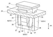
- FIG. The claw portion 22 has a tongue-like insertion portion 32 that can be inserted into the locking hole 24, and a locking portion 33 that protrudes outwardly from the surface side of the insertion portion 32. Is done.
- the locking portion 33 includes a locking surface 34 that can be locked to one edge (the left edge in FIG. 1) on the back surface (lower surface in FIG. 1) side of the locking hole 24, and the locking portion 33.
- the locking surface 34 is formed on the base side of the claw part 22, and the introduction taper part 35 is formed on the tip side of the claw part 22.
- the locking surface 34 has a required inclination angle.
- a pair of claw protection portions 37 is provided on both sides of the claw portion 22 with a slight gap 36, for example, a slit portion or a notch portion.
- the claw protection portion 37 is integrally projected from the resin component 21 and separated from the claw portion 22.
- Side introduction taper portions 38 for guiding insertion into both side edge portions of the locking holes 24 are formed at least at the front end portion of the outer portions of the pair of claw protection portions 37.
- the side-introducing taper portion 38 is an inclined portion that goes toward the center of the width of the claw portion 22 as it advances toward the distal end side. That is, the side introduction taper portion 38 is a tapered inclined portion.
- the above-mentioned “nail support portion 31 at the time of locking” has a function as a lock portion that locks the claw portion 22 so that it does not move by pressing the back surface of the claw portion 22 when the claw portion 22 is locked to the locking hole 24. It is supposed to have.
- the claw support portion 31 at the time of locking can be appropriately provided for the resin component 21, the counterpart component 23, a component existing in the surroundings, and the like.
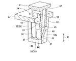
- the above-described “position regulating protrusion 42” has a surface parallel to the insertion portion 32 of the claw portion 22, and is the same as or shorter than the claw portion 22. It is preferable that the length of the portion of the position restricting protrusion 42 to be inserted into the locking hole 24 is at least about twice the wall thickness of the counterpart component 23. In this case, the position restricting protrusion 42 extends to the position of the intermediate portion of the introduction taper portion 35 in the claw portion 22.
- the claw portion 22 elastically deformed by the one edge portion of the locking hole 24 toward the position restricting projection portion 42 does not interfere with the position restricting projection portion 42 or slightly larger than that. It is considered big.
- at least an interval larger than the protruding amount of the locking portion 33 with respect to the insertion portion 32 or an interval slightly larger than the thickness of the insertion portion 32 is used.
- the above-described locking hole 24 has a minimum size or depth dimension that can simultaneously accommodate the claw portion 22 and a position restricting protrusion 42 described later. It is supposed to have.
- transformation of the position control protrusion 42 can be provided in the back side of the position control protrusion 42 as needed.
- the reinforcing rib 42 a is interposed between the resin component 21 and the counterpart component 23.
- the reinforcing rib 42a has a size that does not interfere with the counterpart component 23.
- the reinforcing rib 42a may have a function as an insertion direction position restricting portion for making the position restriction in the insertion direction 41 in contact with the counterpart component 23.
- a side wall portion may be provided between the both side portions of the position restricting projection portion 42 and the outer edge portions of the pair of claw protection portions 37.
- the “protruding wall 43” described above has a surface parallel to the position restricting protrusion 42 and guides the position restricting protrusion 42 in the insertion direction 41.
- the protruding wall 43 supports the back surface of the position restricting protrusion 42 in the direction in which the position restricting protrusion 42 and the claw 22 are separated from each other.
- the protruding wall portion 43 is the same as or slightly longer than the position regulating protruding portion 42.
- the projecting wall portion 43 projects integrally from the inner surface of the counterpart component 23 toward the insertion direction 41 described above.
- the protruding wall portion 43 is formed so that the inner surface thereof is flush with the other edge portion of the locking hole 24.
- a base side abutting portion 46 see FIG.
- the base side abutting portion 46 is a portion closer to the base than the central portion in the length direction of the position restricting protrusion 42 and a portion on the resin component 21 side of the other edge of the locking hole 24. It is provided to touch.
- a distal end side contact portion 47 (see FIG. 1) that contacts the protruding wall portion 43 is set at the distal end portion of the position regulating protrusion 42.
- the above-mentioned “nail support portion 31 at the time of locking” is provided in the extension portion 44 that is integrally extended from the front end side of the protruding wall portion 43 toward the back side of the claw portion 22.
- the claw support portion 31 at the time of locking is configured to support any portion of the back surface on the distal end side of the claw portion 22 while being locked in the locking hole 24.
- the claw support portion 31 at the time of locking is configured to support the back surface of the tip portion of the claw portion 22 while being locked in the locking hole 24.
- a reinforcing rib 44a that can prevent the claw support portion 31 from being deformed when locked can be provided on the back side of the extension portion 44.
- a stop surface 45 for receiving and stopping the tip of the position regulating projection 42 can be formed at the boundary portion between the projection wall 43 and the extension 44 described above.
- the position restricting protrusion 42 also has a position restricting function with respect to the insertion direction 41.
- the base portion side portion of the position restricting protrusion 42 is configured to contact the other edge portion of the locking hole 24 or the edge portion on the position restricting protrusion portion 42 side. Further, the distal end portion of the position regulating projection 42 is configured to abut on the projection wall 43.
- a base-side contact portion 46 (see FIG. 1) is set between the base-side portion of the position-regulating protrusion 42 and the other edge of the locking hole 24.
- the base side abutting portion 46 is a portion closer to the base than the central portion in the length direction of the position restricting protrusion 42, and a portion on the resin component 21 side of the other edge of the locking hole 24. It is provided to touch.
- a distal end side abutting portion 47 (see FIG. 1) that abuts against the projecting wall portion 43 is set at the distal end portion of the position regulating projecting portion 42.
- the protruding wall 43 has the guide surface 48 that guides the tip of the claw 22 toward the claw support 31 at the time of locking.
- the above-described “guide surface 48” is provided in the extension portion 44 on the distal end side of the protruding wall portion 43.
- the guide surface 48 is formed on the surface of the extension portion 44 on the claw portion 22 side, and serves as a guide surface that connects the protruding wall portion 43 and the claw support portion 31 when locked.
- the guide surface 48 described above is an inclined surface that extends downward from the stop surface 45 to the hooking claw support portion 31.
- the mating component 23 has a frame portion 51 that surrounds the periphery of the claw portion 22 in the back of the locking hole 24.
- the frame portion 51 is integrally projected from both side portions of the locking hole 24 on the back surface of the counterpart component 23.
- the frame portion 51 described above includes a pair of side frame portions 52 extending along the outer side portions of the pair of claw protection portions 37 described above, and a horizontal frame portion 53 that connects the tip portions of the pair of side frame portions 52 in the horizontal direction. And a U-shape in side view.
- the frame portion 51 may be configured to reinforce the claw support portion 31 at the time of locking by integrally connecting the claw support portion 31 at the time of locking to the intermediate portion of the horizontal frame portion 53.
- the frame portion 51 has a thickness substantially the same as the depth dimension of both side surfaces of the locking hole 24.
- the “insertion guide portion 55” described above is provided on the surface of the counterpart component 23 on the resin component 21 side and on the edge portion of the locking hole 24 on the claw portion 22 side.
- the insertion guide portion 55 is provided with a protruding portion 56 protruding along the above-described edge portion, and the edge portion of the locking hole 24 on the claw portion 22 side from the side surface on the claw portion 22 side.
- the introduction taper portion is formed over the entire area.
- the introduction taper portion is an inclined surface or the like that is inclined downward toward the inside of the locking hole 24.
- claw support part 31 locks so that the nail
- the claw support part 31 relaxes the stress acting on the claw part 22 when locked, the claw part 22 can be made difficult to break.
- the locking portion 33 of the claw portion 22 when the locking portion 33 of the claw portion 22 is made smaller, the amount of deformation of the claw portion 22 when locked in the locking hole 24 is also reduced, so that the claw portion 22 is more difficult to be plastically deformed. be able to.
- the claw portion 22 is a long cantilever with the base side being continuous with the resin component 21 and the tip side being free, so for example, in the example of FIGS.
- the elastic deformation capability is large and an advantageous structure is provided.
- the proof strength and stability against repeated use are significantly improved than before, and the same or higher than before.
- a locking force can be obtained, and it is possible to achieve both the stability and the locking force with respect to repeated use at a high level.
- the claw portion 22 can be reduced in size and thickness.
- the position regulating protrusion 42 extending in the insertion direction 41 of the claw portion 22 provided on the back side of the claw portion 22 on the back side of the claw portion 22 causes the resin component 21 to be positioned. It is possible to regulate the position with respect to the separation direction of the claw part 22, the direction perpendicular to the claw part 22, or the left-right direction in FIG. 1.
- the position restricting protrusion 42 can be received by the counterpart component 23 via the protruding wall portion 43. it can.
- the position restricting function by the position restricting protrusion 42 can be made more stable.
- the position regulating projection 42 can be guided by the projection wall 43 during insertion.
- the locking claw support portion 31 on the distal end side of the protruding wall portion 43, the back surface of the claw portion 22 which is free is directly supported and fixed by the mating component 23, and the claw portion 22 is fixed. It becomes possible to lock securely. Further, by providing the locking claw support portion 31 on the distal end side of the protruding wall portion 43, the locking claw support portion 31 is installed using the protruding wall portion 43 provided for position regulation or the like. Can do.
- the claw portion 22 is locked to one edge portion of the locking hole 24, and the base side portion of the position restricting protrusion 42, that is, the base side abutting portion 46 is connected to the other edge portion of the locking hole 24.
- the claw portion 22 is in a three-point support state when the tip end portion of the position regulating projection 42, that is, the end side contact portion 47 is brought into contact with the tip end side of the projection wall portion 43. Therefore, the play of the resin component 21 in the locked state can be greatly reduced.
- the claw portion 22 can be held with a longer distance from the support portion 31, the claw portion can be moved in the insertion direction 41 only at a short distance corresponding to the thickness of the counterpart component 23 as in the above example. Compared to those that cannot be held, the claw portion 22 can be held much more firmly, and rattling in the left-right direction in the figure can be suppressed.
- the present invention is not limited to resin parts for automobiles but can be widely applied to resin parts used in various fields.
Landscapes
- Engineering & Computer Science (AREA)
- General Engineering & Computer Science (AREA)
- Mechanical Engineering (AREA)
- Connection Of Plates (AREA)
Abstract
La présente invention se rapporte à une structure pour une mâchoire en résine, ladite structure étant configurée de sorte à améliorer surtout la résistance à la flexion et la stabilité de la mâchoire en résine contre une utilisation répétée. La présente invention se rapporte à une structure de mise en prise de partie en résine qui est configurée de telle manière qu'une section de mâchoire (22) qui est formée d'un seul tenant sur la partie en résine (21) de sorte à faire saillie depuis cette dernière, soit insérée dans un trou de mise en prise (24), vienne en prise avec ce dernier et soit fixée à trou réalisé dans une contre-pièce (23). Une section de support de mâchoire en prise (31) est agencée près du trou de mise en prise (24) et la section de support de mâchoire en prise (31) peut supporter et fixer la surface arrière de la section de mâchoire (22) qui est mise en prise avec le trou de mise en prise (24).
Applications Claiming Priority (4)
| Application Number | Priority Date | Filing Date | Title |
|---|---|---|---|
| JP2012282960A JP6076731B2 (ja) | 2012-12-26 | 2012-12-26 | 樹脂爪構造 |
| JP2012-282959 | 2012-12-26 | ||
| JP2012282959A JP6076730B2 (ja) | 2012-12-26 | 2012-12-26 | 樹脂爪構造 |
| JP2012-282960 | 2012-12-26 |
Publications (1)
| Publication Number | Publication Date |
|---|---|
| WO2014103632A1 true WO2014103632A1 (fr) | 2014-07-03 |
Family
ID=51020726
Family Applications (1)
| Application Number | Title | Priority Date | Filing Date |
|---|---|---|---|
| PCT/JP2013/082539 Ceased WO2014103632A1 (fr) | 2012-12-26 | 2013-12-04 | Structure pour une mâchoire en résine |
Country Status (1)
| Country | Link |
|---|---|
| WO (1) | WO2014103632A1 (fr) |
Cited By (1)
| Publication number | Priority date | Publication date | Assignee | Title |
|---|---|---|---|---|
| CN116141864A (zh) * | 2021-11-19 | 2023-05-23 | 株式会社东海理化电机制作所 | 轮盖 |
Citations (3)
| Publication number | Priority date | Publication date | Assignee | Title |
|---|---|---|---|---|
| JPS6370470U (fr) * | 1986-10-28 | 1988-05-11 | ||
| JP2005098496A (ja) * | 2003-09-05 | 2005-04-14 | Toyota Boshoku Corp | 結合構造 |
| JP2005351244A (ja) * | 2004-06-14 | 2005-12-22 | Denso Corp | ファンシュラウドの取付構造 |
-
2013
- 2013-12-04 WO PCT/JP2013/082539 patent/WO2014103632A1/fr not_active Ceased
Patent Citations (3)
| Publication number | Priority date | Publication date | Assignee | Title |
|---|---|---|---|---|
| JPS6370470U (fr) * | 1986-10-28 | 1988-05-11 | ||
| JP2005098496A (ja) * | 2003-09-05 | 2005-04-14 | Toyota Boshoku Corp | 結合構造 |
| JP2005351244A (ja) * | 2004-06-14 | 2005-12-22 | Denso Corp | ファンシュラウドの取付構造 |
Cited By (1)
| Publication number | Priority date | Publication date | Assignee | Title |
|---|---|---|---|---|
| CN116141864A (zh) * | 2021-11-19 | 2023-05-23 | 株式会社东海理化电机制作所 | 轮盖 |
Similar Documents
| Publication | Publication Date | Title |
|---|---|---|
| US11092179B2 (en) | Clip | |
| US9464647B2 (en) | Pillar garnish mounting structure and tether clip | |
| US9776578B2 (en) | Clip and pillar garnish fixing structure | |
| JP6076731B2 (ja) | 樹脂爪構造 | |
| JP4124169B2 (ja) | プロテクタの車体固定構造 | |
| US20250125563A1 (en) | Connector | |
| JP6076730B2 (ja) | 樹脂爪構造 | |
| JP6025551B2 (ja) | 樹脂部品係止構造 | |
| JP5911023B2 (ja) | 樹脂部材取付構造 | |
| JP2015202783A (ja) | ピラーガーニッシュ取付構造 | |
| JP2022007235A (ja) | ルーフモール及びその端末組付け構造 | |
| JP2009108887A (ja) | 樹脂成形品の組み付け構造 | |
| JP6851268B2 (ja) | 自動車用カバー部材およびその取付構造 | |
| CN114514146B (zh) | 车辆的装饰板 | |
| JP2016196277A (ja) | ガーニッシュの取付構造 | |
| JP2011196397A (ja) | パネルに対する取付部品のクリップによる固定構造 | |
| JP2014126117A (ja) | 樹脂部品係止構造 | |
| JP2023031105A (ja) | テザークリップ及びピラーガーニッシュ取付構造 | |
| JP5741401B2 (ja) | 取付部、バンパーカバーの取付部、及びバンパーカバーの組付構造 | |
| JP2013116683A (ja) | カバー部材の固定構造 | |
| JP2014126129A (ja) | 樹脂部品係止構造 | |
| JP7504814B2 (ja) | クリップ | |
| JP2017067125A (ja) | 爪係止構造 | |
| JP5985225B2 (ja) | バンパ取付け用リテーナ及びバンパ取付け構造 | |
| JP5038936B2 (ja) | パネル部品取付部構造 |
Legal Events
| Date | Code | Title | Description |
|---|---|---|---|
| 121 | Ep: the epo has been informed by wipo that ep was designated in this application |
Ref document number: 13866679 Country of ref document: EP Kind code of ref document: A1 |
|
| NENP | Non-entry into the national phase |
Ref country code: DE |
|
| 122 | Ep: pct application non-entry in european phase |
Ref document number: 13866679 Country of ref document: EP Kind code of ref document: A1 |