WO2014115687A1 - 浸透気化膜およびフェノール濃縮方法 - Google Patents
浸透気化膜およびフェノール濃縮方法 Download PDFInfo
- Publication number
- WO2014115687A1 WO2014115687A1 PCT/JP2014/051007 JP2014051007W WO2014115687A1 WO 2014115687 A1 WO2014115687 A1 WO 2014115687A1 JP 2014051007 W JP2014051007 W JP 2014051007W WO 2014115687 A1 WO2014115687 A1 WO 2014115687A1
- Authority
- WO
- WIPO (PCT)
- Prior art keywords
- pervaporation
- membrane
- pervaporation membrane
- phenol
- polyamide
- Prior art date
- Legal status (The legal status is an assumption and is not a legal conclusion. Google has not performed a legal analysis and makes no representation as to the accuracy of the status listed.)
- Ceased
Links
Images


Classifications
-
- B—PERFORMING OPERATIONS; TRANSPORTING
- B01—PHYSICAL OR CHEMICAL PROCESSES OR APPARATUS IN GENERAL
- B01D—SEPARATION
- B01D71/00—Semi-permeable membranes for separation processes or apparatus characterised by the material; Manufacturing processes specially adapted therefor
- B01D71/06—Organic material
- B01D71/56—Polyamides, e.g. polyester-amides
-
- B—PERFORMING OPERATIONS; TRANSPORTING
- B01—PHYSICAL OR CHEMICAL PROCESSES OR APPARATUS IN GENERAL
- B01D—SEPARATION
- B01D61/00—Processes of separation using semi-permeable membranes, e.g. dialysis, osmosis or ultrafiltration; Apparatus, accessories or auxiliary operations specially adapted therefor
- B01D61/36—Pervaporation; Membrane distillation; Liquid permeation
- B01D61/362—Pervaporation
- B01D61/3621—Pervaporation comprising multiple pervaporation steps
-
- B—PERFORMING OPERATIONS; TRANSPORTING
- B01—PHYSICAL OR CHEMICAL PROCESSES OR APPARATUS IN GENERAL
- B01D—SEPARATION
- B01D69/00—Semi-permeable membranes for separation processes or apparatus characterised by their form, structure or properties; Manufacturing processes specially adapted therefor
- B01D69/02—Semi-permeable membranes for separation processes or apparatus characterised by their form, structure or properties; Manufacturing processes specially adapted therefor characterised by their properties
-
- B—PERFORMING OPERATIONS; TRANSPORTING
- B01—PHYSICAL OR CHEMICAL PROCESSES OR APPARATUS IN GENERAL
- B01D—SEPARATION
- B01D69/00—Semi-permeable membranes for separation processes or apparatus characterised by their form, structure or properties; Manufacturing processes specially adapted therefor
- B01D69/10—Supported membranes; Membrane supports
- B01D69/107—Organic support material
- B01D69/1071—Woven, non-woven or net mesh
-
- B—PERFORMING OPERATIONS; TRANSPORTING
- B01—PHYSICAL OR CHEMICAL PROCESSES OR APPARATUS IN GENERAL
- B01D—SEPARATION
- B01D69/00—Semi-permeable membranes for separation processes or apparatus characterised by their form, structure or properties; Manufacturing processes specially adapted therefor
- B01D69/10—Supported membranes; Membrane supports
- B01D69/108—Inorganic support material
-
- C—CHEMISTRY; METALLURGY
- C02—TREATMENT OF WATER, WASTE WATER, SEWAGE, OR SLUDGE
- C02F—TREATMENT OF WATER, WASTE WATER, SEWAGE, OR SLUDGE
- C02F1/00—Treatment of water, waste water, or sewage
- C02F1/44—Treatment of water, waste water, or sewage by dialysis, osmosis or reverse osmosis
- C02F1/448—Treatment of water, waste water, or sewage by dialysis, osmosis or reverse osmosis by pervaporation
-
- C—CHEMISTRY; METALLURGY
- C07—ORGANIC CHEMISTRY
- C07C—ACYCLIC OR CARBOCYCLIC COMPOUNDS
- C07C37/00—Preparation of compounds having hydroxy or O-metal groups bound to a carbon atom of a six-membered aromatic ring
- C07C37/68—Purification; separation; Use of additives, e.g. for stabilisation
- C07C37/70—Purification; separation; Use of additives, e.g. for stabilisation by physical treatment
- C07C37/82—Purification; separation; Use of additives, e.g. for stabilisation by physical treatment by solid-liquid treatment; by chemisorption
-
- C—CHEMISTRY; METALLURGY
- C02—TREATMENT OF WATER, WASTE WATER, SEWAGE, OR SLUDGE
- C02F—TREATMENT OF WATER, WASTE WATER, SEWAGE, OR SLUDGE
- C02F1/00—Treatment of water, waste water, or sewage
- C02F1/001—Processes for the treatment of water whereby the filtration technique is of importance
-
- C—CHEMISTRY; METALLURGY
- C02—TREATMENT OF WATER, WASTE WATER, SEWAGE, OR SLUDGE
- C02F—TREATMENT OF WATER, WASTE WATER, SEWAGE, OR SLUDGE
- C02F1/00—Treatment of water, waste water, or sewage
- C02F1/02—Treatment of water, waste water, or sewage by heating
- C02F1/04—Treatment of water, waste water, or sewage by heating by distillation or evaporation
-
- C—CHEMISTRY; METALLURGY
- C02—TREATMENT OF WATER, WASTE WATER, SEWAGE, OR SLUDGE
- C02F—TREATMENT OF WATER, WASTE WATER, SEWAGE, OR SLUDGE
- C02F1/00—Treatment of water, waste water, or sewage
- C02F1/44—Treatment of water, waste water, or sewage by dialysis, osmosis or reverse osmosis
- C02F1/441—Treatment of water, waste water, or sewage by dialysis, osmosis or reverse osmosis by reverse osmosis
-
- C—CHEMISTRY; METALLURGY
- C02—TREATMENT OF WATER, WASTE WATER, SEWAGE, OR SLUDGE
- C02F—TREATMENT OF WATER, WASTE WATER, SEWAGE, OR SLUDGE
- C02F1/00—Treatment of water, waste water, or sewage
- C02F1/52—Treatment of water, waste water, or sewage by flocculation or precipitation of suspended impurities
-
- C—CHEMISTRY; METALLURGY
- C02—TREATMENT OF WATER, WASTE WATER, SEWAGE, OR SLUDGE
- C02F—TREATMENT OF WATER, WASTE WATER, SEWAGE, OR SLUDGE
- C02F2101/00—Nature of the contaminant
- C02F2101/30—Organic compounds
- C02F2101/34—Organic compounds containing oxygen
- C02F2101/345—Phenols
-
- C—CHEMISTRY; METALLURGY
- C02—TREATMENT OF WATER, WASTE WATER, SEWAGE, OR SLUDGE
- C02F—TREATMENT OF WATER, WASTE WATER, SEWAGE, OR SLUDGE
- C02F2101/00—Nature of the contaminant
- C02F2101/30—Organic compounds
- C02F2101/36—Organic compounds containing halogen
Definitions
- the present invention relates to a pervaporation membrane and a phenol concentration method.
- Phenolic resin is a typical thermosetting resin, and is used in many fields as parts and insulators that require heat resistance.
- Patent Document 1 discloses a method for treating phenol-containing wastewater, characterized in that the phenol-containing wastewater is supplied to a separator equipped with a pervaporation membrane, and phenol is separated and recovered from the permeate on the decompression side. .
- the pervaporation membrane used in such treatment is concentrated by preferentially permeating phenol and further permeating it. Thereby, the phenol density
- the phenol permeates the pervaporation membrane, it causes deterioration of the pervaporation membrane. And since this deterioration accumulates, there is a problem that the membrane is broken or the phenol permeability is lowered, and the concentration efficiency of phenol is lowered with time.
- An object of the present invention is to provide a pervaporation membrane having excellent durability and a phenol concentration method for efficiently concentrating phenol using such a pervaporation membrane.
- a pervaporation membrane used when concentrating phenol in a liquid containing phenol, water and inorganic ions by a pervaporation method A pervaporation membrane comprising a porous support and a coating layer provided so as to cover the support and made of a polyamide-containing resin.
- Phenol concentration characterized by concentrating phenol in a liquid containing phenol and water by the pervaporation method using the pervaporation membrane according to any one of (1) to (6) above Method.
- a pervaporation membrane having excellent durability when phenol is separated in the pervaporation method can be obtained.
- phenol by using the permeation vaporization membrane, phenol can be efficiently separated and concentrated without frequently replacing the pervaporation membrane.
- FIG. 1 is a diagram showing an example of a pervaporation separation apparatus provided with a pervaporation membrane of the present invention.
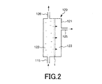
- FIG. 2 is an enlarged view of the pervaporation membrane module in the pervaporation separation apparatus shown in FIG.
- FIG. 3 is a partially enlarged view of the pervaporation membrane shown in FIG.
- FIG. 4A is a process diagram of the phenol concentration method according to the present embodiment
- FIG. 4B is a diagram illustrating a change in an object to be processed in the phenol concentration method according to the present embodiment.
- the phenol concentration method of the present invention is a method of concentrating phenol in a liquid containing phenol, water, and inorganic ions by the osmosis vaporization method using the osmosis vaporization membrane of the present invention.
- the partial pressure of the solute on the liquid phase side is used as the driving force, and the permeation vapor membrane is preferentially permeated for the solute, and the solute is concentrated. is there.
- Such a pervaporation method is performed by a pervaporation separation device equipped with a pervaporation membrane.
- FIG. 1 is a diagram showing an example of an osmosis vapor separation device equipped with an osmosis vapor membrane of the present invention
- FIG. 2 is an enlarged view of an osmosis vaporization module of the osmosis vapor separation device shown in FIG. 1
- FIG. 3 is a partially enlarged view of the pervaporation membrane shown in FIG. 2.
- the permeate vapor separation apparatus 100 shown in FIG. 1 includes a liquid tank 110 to be treated, a pervaporation membrane module 120, a permeate recovery tank 130, and an impermeate storage tank 140.
- the liquid tank 110 to be treated and the pervaporation membrane module 120 are connected by a supply line 115.
- a pretreatment module 150 is provided in the middle of the supply pipeline 115. Examples of the pretreatment module 150 include a module that performs sedimentation treatment using a flocculant, filtration treatment, reverse osmosis membrane treatment, azeotropic treatment, distillation treatment, and the like.
- the permeate vaporization membrane module 120 is connected to the permeate side (secondary side) and the permeate collection tank 130 through a permeate conduit 125, and the supply side (primary side) of the permeate vaporization membrane module 120. And the impermeate storage tank 140 are connected by a discharge pipe 126.
- the pervaporation membrane module 120 includes a housing 121 and a pervaporation membrane 1 provided so as to separate the internal space of the housing 121.
- the primary side of the pervaporation membrane 1 is the supply side space 122
- the secondary side of the permeation vaporization membrane 1 is the permeation side space 123.
- Examples of the liquid to be processed by the pervaporation / separation apparatus 100 include a liquid (solution or dispersion) in which an organic substance is dissolved or dispersed.
- concentration can be performed to increase the concentration of the organic matter in the liquid to be treated by preferentially separating the organic substance from the liquid to be treated by the pervaporation method.
- concentration becomes easy to use as industrial raw materials and the like, leading to an increase in the utility value of the liquid to be treated.
- the volume can be reduced by concentration, and the efficiency of disposal processing and detoxification processing can be increased.
- the concentration of phenol will be described in particular.
- alcohols such as methanol, ethanol, isopropyl alcohol, and butanol
- examples include pyridine, chloroform, and tetrachloroethylene.
- liquid crystal materials for display such as n-butylbenzene classified as endocrine disrupting substances (environmental hormones), 1,2-dibromo-3-chloropropane, 2-butylphenylmethylcarbamate, bendiocarb, etc.
- plasticizers such as diethyl phthalate, coplanar PCB, dibenzo-p-dioxin and the like can also be concentrated.
- examples of the solvent for dissolving the organic substance or the dispersion medium for dispersing the organic substance include water.
- the liquid to be treated may contain an organic substance or a substance other than water, such as an inorganic salt or a dissolved product thereof (inorganic ionic impurity).
- an organic substance or a substance other than water such as an inorganic salt or a dissolved product thereof (inorganic ionic impurity).
- inorganic ions such as sodium ions, potassium ions, sulfate ions, phosphate ions, and ammonium ions.
- the permeation side of the pervaporation membrane module 120 is decompressed by a decompression pump (not shown) connected to the permeation conduit 125.
- the pretreatment module 150 When the liquid to be processed stored in the liquid tank 110 to be processed is sent to the pretreatment module 150 via the supply line 115, the pretreatment is performed there. In the pretreatment, foreign matters in the liquid to be treated are removed, and the volume of the liquid to be treated is reduced.
- the liquid to be treated is sent to the supply side space 122 of the pervaporation membrane module 120 through the supply pipe 115.
- the permeate vaporization membrane 1 is preferentially permeated by the organic matter in the liquid to be treated by depressurizing the permeation side space 123.
- the concentration of the organic substance in the liquid to be processed is increased and the liquid to be processed is concentrated.
- the concentrated liquid to be treated is sent to the permeate collection tank 130 via the permeation pipe 125 and collected.
- the liquid to be processed remaining in the supply-side space 122 of the pervaporation membrane module 120 is sent to the impermeate storage tank 140 through the discharge pipe 126.
- the impervious substance storage tank 140 and the liquid tank 110 to be processed are connected by piping, and the liquid to be processed stored in the impermeable substance storage tank 140 is again connected to the liquid tank 110 to be processed. You may make it return to. Thereby, since the same liquid to be treated can be repeatedly sent to the pervaporation membrane module 120, organic substances that could not be separated in one treatment can be separated more reliably and the recovery rate can be increased.
- the pervaporation membrane 1 shown in FIG. 2 is provided so that the internal space of the housing 121 of the pervaporation membrane module 120 is divided into the supply side space 122 and the permeation side space 123 as described above.
- the form of the pervaporation membrane 1 is not particularly limited, and for example, a dense membrane having a flat membrane type, a hollow fiber type, a tubular type, a bag type, a spiral type or the like can be employed.
- the pervaporation membrane 1 has a porous support 11 and a coating layer 12 provided so as to cover the support 11 and made of a polyamide-containing resin. In other words, the support 11 is embedded in the coating layer 12. Since the coating layer 12 included in the pervaporation membrane 1 has an excellent affinity for organic substances, the organic substances in the liquid to be treated are preferentially permeated. For this reason, the organic substance in a to-be-processed liquid can be isolate
- the entire surface of the support 11 may not be covered with the coating layer 12, and a part of the surface may be exposed. Even in this case, since the support 11 can reinforce the coating layer 12, the effect of improving the mechanical properties of the pervaporation membrane 1 can be obtained.
- the covering layer 12 is a dense layer provided so as to cover the support 11.
- the covering layer 12 is made of a polyamide-containing resin.
- Such a polyamide-containing resin is not particularly limited as long as it is a polymer having a repeating unit containing an amide bond. Although details are unknown, since the amide bond has a high affinity for the organic substance, the coating layer 12 made of the polyamide-containing resin efficiently adsorbs the organic substance (particularly phenol, the same applies hereinafter), Permeated and preferentially permeated. Therefore, the pervaporation membrane 1 provided with the coating layer 12 is particularly excellent in separation characteristics.
- Such a polyamide-containing resin may be, for example, a polyamide resin such as nylon 6, nylon 66, nylon 12, or the like, and may be a polymer alloy or a polymer blend containing these polyamide resins.
- the copolymer has a repeating unit containing a bond.
- a copolymer having a polyamide segment composed of a repeating unit containing an amide bond and another segment copolymerizable with the polyamide segment is preferably used.
- the affinity for the organic matter in the liquid to be treated is expressed mainly by the polyamide segment, and the mechanical properties of the pervaporation membrane 1 are enhanced.
- an organic substance is permeated into the pervaporation film 1, and the organic substance is permeated while the pervaporation film 1 is swollen.
- the pervaporation membrane 1 may be deteriorated, resulting in tearing or a decrease in separation characteristics.
- the pervaporation membrane 1 containing the copolymer the deterioration of the mechanical properties due to the swelling is suppressed by the polyamide segment, and the other segment increases the permeability of the organic matter, so that the organic matter is the pervaporation membrane. Even if it permeates into 1 and swells, the accompanying deterioration is suppressed and the durability is considered to be enhanced.
- segments copolymerizable with the polyamide segment include, for example, a polyether segment composed of a repeating unit containing an ether bond, a polyester segment composed of a repeating unit containing an ester bond, and a repeating unit containing an ethylene structure.
- Polyethylene segments, polypropylene segments composed of repeating units containing a propylene structure, polysiloxane segments composed of repeating units containing a siloxane bond, etc. are used, and one or more of these are used in combination be able to.
- the other segment copolymerizable with the polyamide segment preferably includes a polyether segment.
- the polyether segment is easily copolymerized with the polyamide segment, and is more flexible than the polyamide segment. For this reason, even when a large external force is applied to the pervaporation membrane 1, it is possible to prevent the pervaporation membrane 1 from being easily broken. Further, the polyether segment has a low affinity for many organic substances, and therefore, the significant deterioration of the pervaporation film 1 due to the permeation and swelling of the organic substance in the pervaporation film 1 can be suppressed. As a result, it is possible to obtain the pervaporation membrane 1 in which the separation characteristics and durability of the organic matter are more highly compatible.
- the polyether segment has hydrophilicity
- the pervaporation film 1 including the polyether segment has high contact with the liquid to be treated.
- the above-mentioned polyamide segment has lipophilicity.
- the organic substance in the to-be-treated liquid permeates efficiently into the lipophilic part of the pervaporation membrane 1.
- the other segments that can be copolymerized with the polyamide segments are preferably those having hydrophilicity.
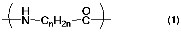
- the following formula (1) is an example of the structural formula of the polyamide segment.
- n is an integer of 1 to 8.
- m is an integer of 1-8.
- the copolymer including the polyamide segment and the other segment preferably includes the polyamide segment in a proportion of 10 to 90 mol%, more preferably includes a proportion of 20 to 80 mol%, and more preferably 30 to 75 mol. It is more preferable that it is contained at a rate of 45%, particularly preferably 45% to 75% by mole.
- high affinity for organic substances mainly expressed by the polyamide segment, high mechanical properties imparted to the pervaporation membrane 1, and high permeability for organic components mainly ensured by other segments. Are expressed almost without being buried.
- separation characteristic in the coating layer 12 by the support body 11 being embedded by suppressing the ratio of each segment in the said range is suppressed.
- the support 11 when the support 11 is embedded, the support 11 is positioned on the permeation path of the substance that permeates the pervaporation membrane 1, and the effective area of the pervaporation membrane 1 is apparently reduced. As a result, the separation characteristics may be reduced, but by keeping the ratio of each segment within the above range, the polyamide segment promotes the adsorption and penetration of organic substances as much as possible, thereby avoiding the influence of the support 11. Can do.
- the support 11 since the support 11 is embedded, the mechanical properties of the pervaporation membrane 1 can be improved. For example, even if the copolymer including the polyamide segment and other segments swells, the pervaporation membrane It is suppressed that 1 deteriorates until it loses the function as a partition.
- the pervaporation membrane 1 that reliably satisfies both the separation property and durability of the organic matter can be obtained.
- the permeability of the organic matter is improved, so that the time for the organic matter to stay in the pervaporation membrane 1 is shortened, and it becomes difficult to swell, and the separation characteristics are further improved. It can be increased.
- the copolymer containing the polyamide segment may be any of a block copolymer, a random copolymer and an alternating copolymer, but is preferably a block copolymer.
- polymer alloy or polymer blend containing polyamide resin examples include those obtained by adding polyethylene, polypropylene, polystyrene, polyacrylate, polyacrylamide, polydimethylsiloxane, polyvinylpyrrolidone, polyurethane, etc. to polyamide resin. One of them or a mixture of two or more of them is used. All of these are considered to contribute to the reinforcement of the polyamide resin without inhibiting the adsorption and penetration of organic substances by the polyamide resin. Therefore, from the viewpoint of making the separation characteristics and durability of the pervaporation membrane 1 compatible, polymer alloys and polymer blends containing these resin components together with polyamide resins are useful.
- the durability can be further improved by irradiating the pervaporation membrane 1 with an electron beam. This is considered to be because cross-linking occurs between these resins and polyamide by the electron beam irradiation treatment.
- polyethylene is preferably used from the viewpoints of chemical resistance, long-term stability, and mechanical strength.
- the average thickness of the pervaporation membrane 1 is not particularly limited as long as it has a mechanical strength necessary to separate the liquid phase and the gas phase, but is about 10 to 500 ⁇ m.
- the thickness is preferably about 20 to 400 ⁇ m.
- the Shore D hardness of the cured product of the polyamide-containing resin is preferably about 15 to 85, and more preferably about 20 to 75. By setting the Shore D hardness within the above range, it is possible to secure sufficient separation characteristics while suppressing the pervaporation membrane 1 from being broken or stretched during the separation by the pervaporation method.
- the Shore D hardness of the polyamide-containing resin is measured by a measurement method defined in ISO 868.
- the flexural modulus of the cured product of the polyamide-containing resin is preferably about 10 to 550 MPa, more preferably about 25 to 400 MPa, and further preferably about 40 to 300 MPa.
- the flexural modulus of the polyamide-containing resin is measured by a measuring method defined in ISO 178. The thickness of the test piece is 100 ⁇ m, the width of the test piece is 10 mm, and the distance between fulcrums is 50 mm.
- the melting point of the cured product of the polyamide-containing resin is preferably about 110 to 185 ° C., more preferably about 130 to 175 ° C.
- the melting point of the polyamide-containing resin is measured by a measurement method defined in ASTM D3418.
- the heat distortion temperature of the cured product of the polyamide-containing resin is preferably about 35 to 140 ° C., more preferably about 40 to 130 ° C.
- the heat distortion temperature of the polyamide resin is preferably about 35 to 140 ° C., more preferably about 40 to 130 ° C.
- the copolymer containing a polyamide segment and a polyether segment can be produced by a known synthesis method.
- the synthesis method include polycondensation of polyamide-forming monomers such as lactams, ⁇ -amino acids, or diamines and dicarboxylic acids in the presence of polyalkylene ethers having an amino group at the terminal or organic acid salts thereof.
- a method of polycondensation of the aforementioned polyamide-forming monomer in the presence of a polyalkylene ether having a carboxyl group at the terminal or an organic amine salt thereof, an amino group, a carboxyl group, or both an amino group and a carboxyl group at the terminal For example, a method of polycondensing the above-mentioned polyamide-forming monomer in the presence of a polyalkylene ether having the following.
- the polyamide-containing resin may be formed, and then the shape may be transferred to the surface of the pervaporation film 1 by pressing a mold having a predetermined uneven shape. . Thereby, the surface area of the pervaporation membrane 1 can be increased, and the permeation flux of the pervaporation membrane 1 can be increased.
- the pervaporation membrane 1 includes a support 11.
- the support 11 is provided inside or on the surface of the pervaporation membrane 1 and reinforces the membrane structure to increase the overall mechanical strength.
- the pervaporation membrane 1 shown in FIG. 3 (a) has the above-described coating layer 12 and a support 11 provided to be embedded therein.
- Examples of the shape of the support 11 include non-woven fabrics, fabrics such as woven fabrics, punching materials, and netting materials. Since these all have a plurality of openings, they can be said to be porous bodies, and these openings serve as paths for organic substances.
- the covering layer 12 is provided so as to close the opening, and the organic substance permeates the covering layer 12 so as to permeate the pervaporation membrane 1.
- examples of the woven structure of the woven fabric include plain weave, Nanako weave, satin weave, and twill weave, but are not particularly limited.
- the constituent material of the support 11 includes, for example, inorganic fibers such as glass fiber, ceramic fiber, carbon fiber, and metal fiber, acrylic fiber, nylon fiber, aramid fiber, polyester fiber, polyethylene fiber, polypropylene fiber, Examples thereof include synthetic fibers such as rayon fibers, and organic fibers such as natural fibers such as hemp, cotton, kenaf, and jute. Among these, one kind or two or more kinds of composite fibers are used. Of these, the support 11 composed of glass fiber or organic fiber is preferably used, and the support 11 composed of glass fiber is more preferably used. Such a support 11 is useful as a support for the pervaporation membrane 1 that continues to receive pressure over a long period of time because it has both excellent flexibility and mechanical properties. That is, the pervaporation membrane 1 having excellent durability can be obtained because it is difficult to break or open even under pressure.
- inorganic fibers such as glass fiber, ceramic fiber, carbon fiber, and metal fiber, acrylic fiber, nylon fiber, aramid fiber, polyester fiber, polyethylene fiber, polypropylene
- those containing at least one of nylon fibers and aramid fibers are preferably used. Since these materials contain an amide bond in the constituent material, a support having particularly high adhesion to a polyamide-containing resin can be obtained. For this reason, even if the support body 11 is included, it is difficult for gaps and holes to occur in the pervaporation membrane 1, and the permeation vaporization membrane 1 can be obtained, which can more reliably suppress the occurrence of liquid leakage. Such an effect can be obtained not only when nylon fibers and aramid fibers are used, but also when other fibers containing amide bonds are used.
- the occupation ratio (volume fraction) of the support 11 in the pervaporation membrane 1 is not particularly limited, but is preferably about 20 to 90% by volume, more preferably about 30 to 80% by volume. . Thereby, the mechanical characteristics of the pervaporation membrane 1 can be further improved without inhibiting the separation characteristics of the polyamide-containing resin.
- the occupation ratio (area fraction) of the support is not particularly limited, but is preferably about 10 to 95%, and preferably about 20 to 90%. Is more preferable. As a result, sufficient mechanical characteristics can be ensured, and the support 11 can prevent the separation characteristics of the pervaporation membrane 1 from being significantly disturbed. In other words, the balance between the mechanical properties and the aperture ratio of the pervaporation membrane 1 can be optimized, and both can be achieved.
- Such a support 11 is impregnated with the above-described polyamide-containing resin or cast, and then pressed with a roll or the like as necessary, whereby the pervaporation membrane 1 including the support 11 is obtained.
- the polyamide-containing resin is used after being melted or diluted with an organic solvent or the like as necessary.
- a coating device such as a doctor blade is preferably used.
- the support 11 an uneven shape derived from the shape of the support 11 is likely to occur on the surface of the pervaporation membrane 1 (the surface of the coating layer 12).
- the surface area of the pervaporation membrane 1 is increased, so that organic substances can easily permeate and the separation efficiency can be improved.
- the pervaporation membrane 1 may be easily broken starting from the concave portion or the like.
- the surface roughness of the pervaporation membrane 1 is preferably such that the arithmetic average roughness Ra is about 0.005 to 40 ⁇ m on the surface facing the supply-side space 122 (surface on the liquid contact side).
- the thickness is about 0.01 to 30 ⁇ m.
- the surface facing the transmission side space 123 (the surface on the detachment side) is preferably about 0.005 to 80 ⁇ m, more preferably about 0.01 to 70 ⁇ m.
- the arithmetic average roughness Ra of the surface facing the transmission side space 123 is preferably larger than the arithmetic average roughness Ra of the surface facing the supply side space 122, specifically 1.01. It is preferably about 10000 times, more preferably about 1.05 to 5000 times.
- the organic matter penetration efficiency on the surface facing the supply-side space 122 and the organic matter desorption efficiency on the surface facing the transmission-side space 123 are respectively optimized. Can do.
- the penetration efficiency and desorption efficiency are optimized by defining the surface roughness of each surface so that the desorption rate is moderately higher than the penetration rate. In addition, it is possible to suppress a decrease in mechanical properties.
- the support 11 and the covering layer 12 are formed by a pressing member having a relatively flexible contact surface when the pervaporation membrane 1 is manufactured. May be pressurized. Thereby, the shape derived from the support body 11 is easily reflected on the surface of the coating layer 12.
- the contact surface having relatively high flexibility include a rubber material such as silicone rubber and urethane rubber, and a member surface made of various elastomer materials.
- FIG.3 (b) is sectional drawing which shows the other structural example of the pervaporation membrane 1 shown to Fig.3 (a).
- the pervaporation membrane 1 shown in FIG. 3 (b) has a coating layer 12 and a permeation shown in FIG. 3 (a) except that it has a support 11 laminated on one surface of the coating layer 12.
- Such a pervaporation film 1 is formed by a method of placing an uncured or unsolidified coating layer 12 on one surface of a support 11 and applying pressure while heating.
- the coating layer 12 and the support body 11 may each be provided with two or more in the one pervaporation film
- two coating layers 12 may be laminated so that one support 11 is sandwiched, or three coating layers 12 and two supports 11 may be alternately sandwiched and laminated. .
- the liquid to be treated when the liquid to be treated is a phenol aqueous solution, its concentration is usually as low as 1 to 2% by mass if it is a waste liquid or the like, and as such is suitable for industrial use (eg, use as a phenol raw material). Absent. Further, the liquid to be treated is often a factory waste liquid or the like, and in that case, it contains impurities such as inorganic salts and polymers in addition to phenol and water. In order to use an aqueous phenol solution industrially, it is generally considered that the phenol concentration needs to be 70% by mass or more, and therefore, a separation and concentration method such as a pervaporation method is indispensable.
- zeolite permeation membranes have been known.
- the A-type zeolite membrane which is in practical use, is a water-permeable porous membrane and, unlike the pervaporation membrane according to the present invention, works to preferentially permeate water from an aqueous phenol solution (the present invention).
- the polymer when a polymer or the like is included in addition to phenol or water, the polymer clogs the membrane surface, and the separation characteristics Decreases. Furthermore, ion exchange occurs between the inorganic salt contained in the aqueous phenol solution and the surface of the zeolite membrane, and the separation characteristics are also lowered.
- the pervaporation membrane composed of ZSM-5 type zeolite or silicalite is a membrane that permeates organic matter, like the pervaporation membrane according to the present invention, but these are porous membranes and dense membranes. It is different from a certain present invention.
- the porous membrane has a problem that clogging due to impurities such as inorganic salts and polymers is likely to occur, and the deterioration of the separation characteristics due to this is unavoidable.
- the pervaporation membrane composed of polydimethylsiloxane is an organic permeable membrane and a dense membrane, the above-described clogging hardly occurs, but has a problem that the separation property of organic matter is low.
- the pervaporation membrane 1 includes a support 11 and a dense coating layer 12 made of a polyamide-containing resin, so that the liquid to be treated is an impurity such as an inorganic salt or a polymer. Even when it contains, the separation property and durability of the organic matter can be made highly compatible. As a result, it is possible to continuously separate and concentrate the pervaporation membrane 1 over a long period of time with respect to the liquid to be treated that is dilute and contains impurities while suppressing the replacement frequency. As a result, it is possible to efficiently obtain an industrially available phenol raw material and a liquid to be treated that can perform disposal or detoxification at a low cost.
- the pervaporation membrane 1 according to the present invention is useful in that it can be subjected to separation and concentration treatment over a long period of time even for liquids containing 0.1 mass% or more of inorganic ions.
- the conventional pervaporation membrane has a problem that not only the separation characteristics are remarkably lowered but also the membrane is deteriorated in a short time, and the efficiency of separation and concentration treatment is remarkably lowered.
- the pervaporation membrane 1 according to the present invention includes the support 11 and the coating layer 12, thereby making it possible to reliably solve these problems. As a result, it is possible to obtain the pervaporation membrane 1 that can be efficiently separated and concentrated without performing a process such as removing inorganic ions in advance.
- a strongly basic liquid to be treated having a pH exceeding 7 or pH 8 could not be applied over a long period of time. According to 1, it is possible to efficiently separate and concentrate such a liquid to be processed over a long period of time.
- the pervaporation membrane 1 may contain a filler as necessary.
- the filler is particles dispersed in the polyamide-containing resin and acts to enhance various properties of the pervaporation membrane 1, such as mechanical properties.
- Examples of the shape of the filler include a spherical shape, a plate shape (scale shape), and a needle shape.
- the average particle size of the filler is preferably about 0.01 to 20 ⁇ m, more preferably about 0.05 to 10 ⁇ m.
- the average particle diameter of a filler is a particle diameter when accumulation becomes 50% on a mass basis in the particle size distribution obtained by the laser diffraction type particle size measurement method.
- constituent material of the filler examples include inorganic materials such as silica, alumina, titania, zirconia, mica, clay, and zeolite, organic materials such as phenol resin, acrylic resin, acrylonitrile resin, polyurethane, polyvinyl chloride, polystyrene, and polyamide. Materials and the like. Among these, zeolite is preferably used from the viewpoint of phenol separation efficiency, and hydrophobic zeolite is more preferably used.
- the occupancy rate of the filler in the pervaporation membrane 1 is not particularly limited, but is preferably smaller than the occupancy rate of the support 11, specifically about 2 to 40% by volume, preferably 10 to 35%. More preferably, it is about volume%. Thereby, the mechanical characteristics of the pervaporation membrane 1 can be further improved without inhibiting the separation characteristics of the polyamide-containing resin.
- Examples of such surface treatment include coupling agent treatment and plasma treatment.
- the pervaporation film 1 may be subjected to electron beam irradiation treatment as necessary.
- the electron beam irradiation process is a process for modifying the coating layer 12 or the like by irradiating it with an electron beam.
- an electron beam is irradiated onto the coating layer 12 made of the polyamide-containing resin as described above, the surface of the coating layer 12 as well as the surface of the coating layer 12 is modified by the energy of the electron beam. And the crosslinking density of the polymer in a layer is raised and mechanical strength is improved.
- the durability of the pervaporation membrane 1 can be further enhanced, such as being less likely to deteriorate even if it swells.
- the electron beam irradiation treatment it is considered that a functional group such as an amide bond or chemical bond that has an affinity with an organic substance or a chemical bond is not easily lost or modified. For this reason, the mechanical strength is improved as described above, while the separation property of the organic substance is hardly deteriorated.
- the pervaporation membrane 1 is useful in that the separation property of the organic matter is hardly lowered and is not easily broken even when subjected to the pervaporation process for a long period of time.
- the functional group is introduced to the surface of the film by electron beam irradiation, and the contact property with the liquid to be treated is improved.
- the contact property between the organic substance and the membrane is improved, and the separation property of the organic substance is enhanced. Therefore, by performing the electron beam irradiation treatment on the coating layer 12 made of the polyamide-containing resin, the pervaporation membrane 1 in which the separation property and the durability of the organic matter are particularly highly compatible can be obtained.
- Electron beam is a kind of radiation, which is a bundle of electrons accelerated by an accelerator or the like.
- the electron beam is scanned with respect to a film made of a polyamide-containing resin so that a uniform integrated irradiation amount is applied to the surface to be processed. Can do.
- the scanning pattern of the electron beam is not particularly limited, and the integrated dose may not be uniform.
- the integrated dose (absorbed dose) of the electron beam is not particularly limited, but is preferably about 25 to 300 kGy, and more preferably about 30 to 200 kGy.
- the mechanical group of the coating layer 12 can be reliably suppressed while the functional groups and chemical bonds responsible for the organic matter are lost or denatured. The strength can be improved.
- the pervaporation membrane 1 which can maintain such an effect over a long period of time is obtained.
- the acceleration voltage when accelerating electrons to obtain an electron beam is preferably about 10 to 200 kV, more preferably about 20 to 150 kV.
- the acceleration voltage affects the penetration depth of the electron beam into the coating layer 12. Therefore, by setting the acceleration voltage within the above range, necessary and sufficient processing can be performed on the entire coating layer 12 in the thickness direction. As a result, the compatibility between the separation characteristics and the durability can be further enhanced.
- the electron beam irradiation treatment is particularly effective in achieving both the separation characteristics and durability of the membrane. That is, although the polyether segment has a high organic component permeability, the film structure is likely to be moderately strengthened by the electron beam irradiation treatment. For this reason, while maintaining the feature of the polyether segment with high permeability of the organic component, it also improves the durability against swelling of the organic matter, and has two effects that cannot be achieved by simply increasing the permeability of the organic component. At the same time, the pervaporation membrane 1 can be obtained.
- the pervaporation membrane 1 is installed in the above-described pervaporation membrane module 120, it is preferable that the permeation vaporization membrane module 120 be installed so that the irradiation surface of the electron beam faces the supply side space 122.
- the electron beam irradiation treatment is preferably performed in the presence of an inert gas.
- an inert gas thereby, it can suppress that oxygen influences an electron beam irradiation part, and can prevent that the functional group and chemical bond which have affinity with organic substance lose
- the oxygen concentration is preferably 500 ppm or less by mass ratio.
- the inert gas include nitrogen gas and argon gas.
- the pervaporation membrane of the present invention is a laminated film in which a plurality of pervaporation membranes 1 as described above are laminated, or a laminated film in which the pervaporation membrane 1 and other films are laminated. Etc. Even in this case, the same effect as the above-described pervaporation membrane 1 is obtained.
- the pervaporation membrane 1 can take various forms as described above, but here, a case of manufacturing a flat membrane type will be described.
- the flat membrane type pervaporation membrane 1 is obtained by, for example, melting a raw material at a temperature of about 180 to 230 ° C., and molding the obtained melt into a flat membrane by a molding method such as an extrusion method, an injection molding method, or a press method. Manufactured by doing.
- the raw material may be diluted with a solvent or the like as necessary.
- the surface of the pervaporation membrane 1 may be subjected to a surface treatment different from the electron beam irradiation treatment, if necessary.
- a surface treatment different from the electron beam irradiation treatment
- examples of such surface treatment include corona discharge treatment, arc discharge treatment, excimer light irradiation treatment, plasma treatment, etching treatment, and coating treatment.
- Examples of the coating process include a process of introducing a functional group having a high affinity for the organic substance to be separated by coating.
- FIG. 4A is a process diagram of the phenol concentration method according to the present embodiment
- FIG. 4B is a diagram illustrating a change in an object to be processed in the phenol concentration method according to the present embodiment.
- the phenol concentration method shown in FIG. 4 uses the pretreatment step S1 for pretreating the liquid to be treated A1 and the permeation vaporization method using the pervaporation membrane 1 for the pretreated liquid A2 to be treated. It has an osmotic vaporization step S2 for preferentially vaporizing phenol in the liquid A2, and a condensation step S3 for condensing the permeate A3 in the gaseous state to obtain a condensate A4 in the liquid or solid state. By passing through these steps, a condensate A4 enriched with phenol can be obtained.
- each process is explained in full detail.
- Pretreatment step S1 In the pretreatment step S1, as described above, by performing a sedimentation treatment using a flocculant, a filtration treatment, a reverse osmosis membrane treatment, an azeotropic treatment, a distillation treatment, etc., foreign matter in the liquid to be treated A1 is removed, The volume of the liquid A1 to be treated is reduced. Among these, in the reverse osmosis membrane treatment, water contained in the liquid to be treated A1 is removed using a reverse osmosis membrane (RO membrane) to increase the phenol concentration. As a result, volume reduction of the to-be-processed liquid A1 will be achieved. A liquid A2 to be treated is obtained through such pretreatment.
- RO membrane reverse osmosis membrane
- pretreatment step S1 may be performed as necessary, and may be omitted depending on the amount of the liquid A1 to be treated and the composition and concentration of the organic matter contained therein.
- Permeation vaporization step S2 In the pervaporation step S2, the liquid A2 to be treated is supplied to the supply-side space 122 of the pervaporation membrane module 120 shown in FIG. At this time, the permeation side space 123 of the pervaporation membrane module 120 is decompressed. Thereby, the phenol in the to-be-processed liquid A2 permeate
- the pressure in the permeate side space 123 is preferably about 10 to 7000 Pa, more preferably about 50 to 5000 Pa. By setting the pressure in the permeation side space 123 within the above range, phenol can be efficiently concentrated.
- the temperature of the liquid A2 to be treated is preferably about 30 to 95 ° C., more preferably about 40 to 80 ° C. By setting the temperature of the liquid to be processed A2 within the above range, the processing efficiency in the liquid to be processed A2 can be increased.
- the pervaporation membrane 1 can separate and concentrate the organic substance in the liquid to be treated containing the organic substance, but is particularly useful in the separation and concentration of phenol. This is due to the relationship between the molecular structure of phenol and the composition of the pervaporation membrane 1, and specifically, it is considered that phenol has a high affinity for the structure in the polyamide. Further, the pervaporation membrane 1 has a high separation performance for phenol, while minimizing the deterioration of the membrane due to the permeation of phenol. This is because the coating layer 12 made of a polyamide-containing resin and the support 11 that supports the coating layer 12 are provided. The support 11 does not impair the separation characteristics of the coating layer 12 and the durability of the membrane. It is thought that it is because the sex is improved.
- phenol can be efficiently separated and concentrated over a long period of time. Further, since the deterioration of the pervaporation membrane 1 due to the pervaporation of phenol is minimized, the pervaporation membrane can continue the phenol separation process for a long time without replacement or while minimizing the replacement frequency. 1 is obtained.
- Condensing step S3 In the condensing step S3, the gaseous permeate A3 is condensed. As a result, the permeate A3 is liquefied and a liquid condensate A4 is obtained. Depending on the condensation conditions, solid state condensate A4 is obtained.
- the permeate A3 may be pressurized (returned to normal pressure) or cooled.
- various coolers and coolants such as liquid nitrogen may be used for cooling.
- the condensation step S3 may be provided as necessary.
- the condensation step S3 may be replaced by a step of selectively depositing solid or liquid phenol from the gaseous permeate A3.
- This precipitation utilizes the fact that there is a difference in temperature and pressure at which state changes occur between phenol and water. That is, when the phase diagrams of phenol and water are compared, there is a difference in the temperature and pressure through which the vapor-liquid equilibrium line and the solid-gas equilibrium line pass between the two. Precipitation of phenol is possible by selectively changing the state of phenol.
- the permeate A3 in the gas state is changed into the solid state.
- phenol can be selectively precipitated. The same applies when depositing phenol in a liquid state.
- any desired process may be added.
- the said phenol concentration method is applicable also to organic substances other than phenol.
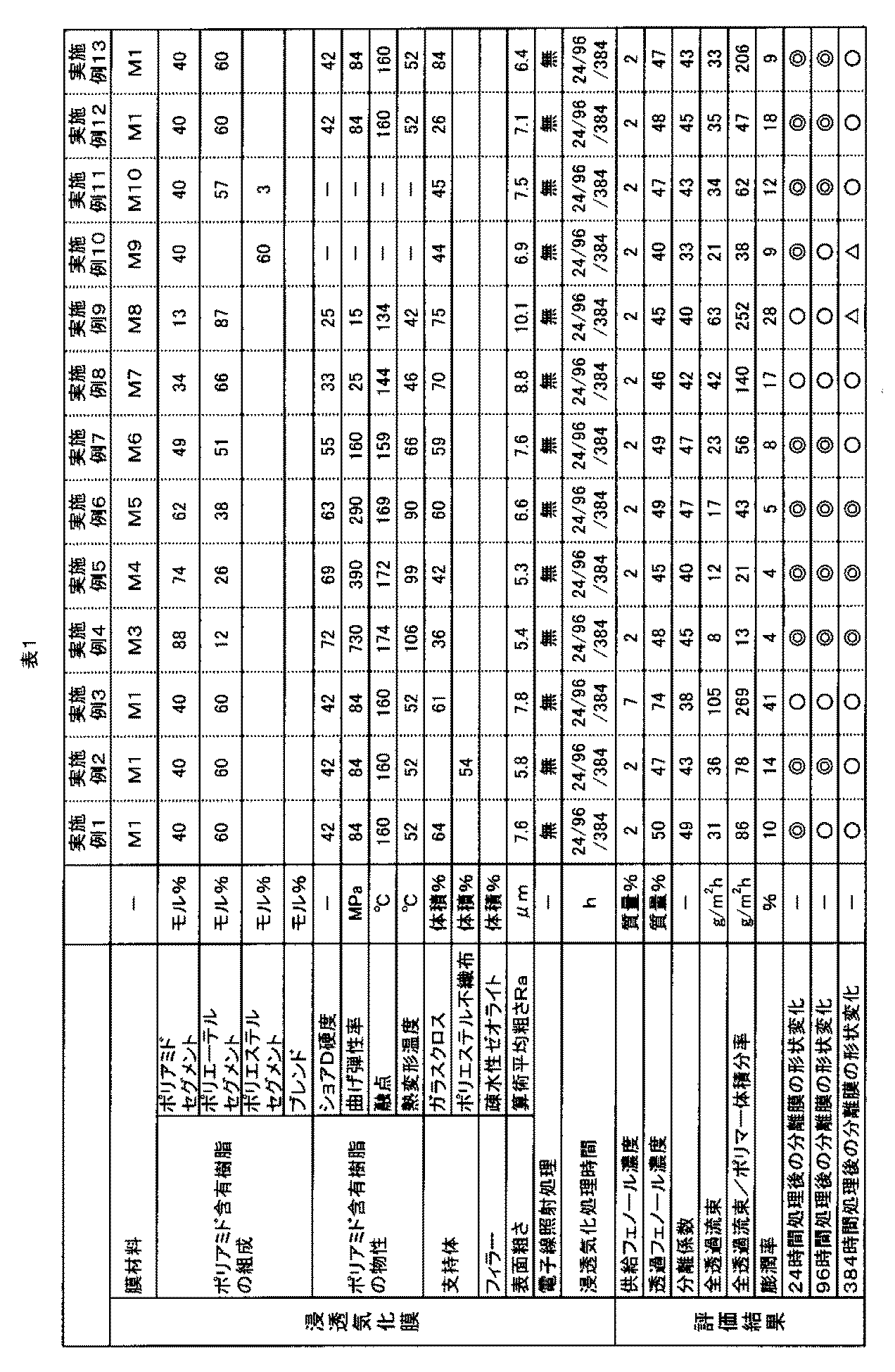
- Example 1 Formation of Flat Film First, the film material M1 was heated and melted at 200 ° C., and the obtained melt was formed into a flat film by an extrusion method. As a result, a flat membrane was obtained.
- the film material M1 is a block copolymer including the segments shown in Table 1.
- the permeation side space of the pervaporation membrane module was decompressed to 133 Pa by a decompression pump.
- the vapor phase component that permeated through the pervaporation membrane was liquefied and collected by a glass trap cooled with liquid nitrogen. This obtained the concentrate.
- a circulation route was constructed so that the aqueous phenol solution discharged through the pervaporation membrane module without passing through the pervaporation membrane was again supplied to the supply-side space.
- Example 2 An osmosis vaporized membrane was obtained in the same manner as in Example 1 except that the support was changed to the following, and an osmotic vaporization treatment was performed on the aqueous phenol solution.
- a polyester nonwoven fabric manufactured by Nippon Vilene, MF90, mass 90 g / m 2 was used as the support.
- the obtained pervaporation membrane had an average thickness of 130 ⁇ m. Further, the occupation ratio occupied by the polyamide-containing resin in the pervaporation membrane was 46% by volume.
- Example 3 The phenol aqueous solution was subjected to pervaporation treatment in the same manner as in Example 1 except that an aqueous solution (pH 8.0) having a phenol concentration of 7% by mass and an inorganic ionic impurity concentration of 1% by mass was used.
- the occupancy rate (volume fraction) of the support was changed to the values shown in Table 1.
- Example 4 A pervaporation membrane was obtained in the same manner as in Example 1 except that the membrane material M1 was changed to the membrane material M3 and the occupation ratio (volume fraction) of the support was changed to the value shown in Table 1. The aqueous solution was subjected to pervaporation.
- the film material M3 is a block copolymer including the segments shown in Table 1.
- Example 5 A pervaporation membrane was obtained in the same manner as in Example 1 except that the membrane material M1 was changed to the membrane material M4 and the occupation ratio (volume fraction) of the support was changed to the value shown in Table 1.
- the aqueous phenol solution was subjected to pervaporation.
- the film material M4 is a block copolymer including the segments shown in Table 1.
- Example 6 A pervaporation membrane was obtained in the same manner as in Example 1 except that the membrane material M1 was changed to the membrane material M5 and the occupation ratio (volume fraction) of the support was changed to the value shown in Table 1. The aqueous phenol solution was subjected to pervaporation.
- the film material M5 is a block copolymer including the segments shown in Table 1.
- Example 7 A pervaporation membrane was obtained in the same manner as in Example 1 except that the membrane material M1 was changed to the membrane material M6 and the occupation ratio (volume fraction) of the support was changed to the value shown in Table 1. The aqueous phenol solution was subjected to pervaporation.
- the film material M6 is a block copolymer including the segments shown in Table 1.
- Example 8 A pervaporation membrane was obtained in the same manner as in Example 1 except that the membrane material M1 was changed to the membrane material M7 and the occupation ratio (volume fraction) of the support was changed to the value shown in Table 1. The aqueous phenol solution was subjected to pervaporation.
- the film material M7 is a block copolymer including the segments shown in Table 1.
- Example 9 A pervaporation membrane was obtained in the same manner as in Example 1 except that the membrane material M1 was changed to the membrane material M8 and the occupation ratio (volume fraction) of the support was changed to the value shown in Table 1.
- the aqueous phenol solution was subjected to pervaporation.
- the film material M8 is a block copolymer including the segments shown in Table 1.
- Example 10 A pervaporation membrane was obtained in the same manner as in Example 1 except that the membrane material M1 was changed to the membrane material M9 and the occupation ratio (volume fraction) of the support was changed to the value shown in Table 1.
- the aqueous phenol solution was subjected to pervaporation.
- the film material M9 is a block copolymer including the segments shown in Table 1.
- Example 11 A pervaporation membrane was obtained in the same manner as in Example 1 except that the membrane material M1 was changed to the membrane material M10 and the occupation ratio (volume fraction) of the support was changed to the value shown in Table 1.
- the aqueous phenol solution was subjected to pervaporation.
- the film material M10 is a block copolymer including the segments shown in Table 1.
- Example 12 An osmosis vaporization membrane was obtained in the same manner as in Example 1 except that the occupancy rate (volume fraction) of the support was changed to the value shown in Table 1, and an osmosis vaporization treatment was performed on the phenol aqueous solution.
- Example 13 An osmosis vaporization membrane was obtained in the same manner as in Example 1 except that the occupancy rate (volume fraction) of the support was changed to the value shown in Table 1, and an osmosis vaporization treatment was performed on the phenol aqueous solution.
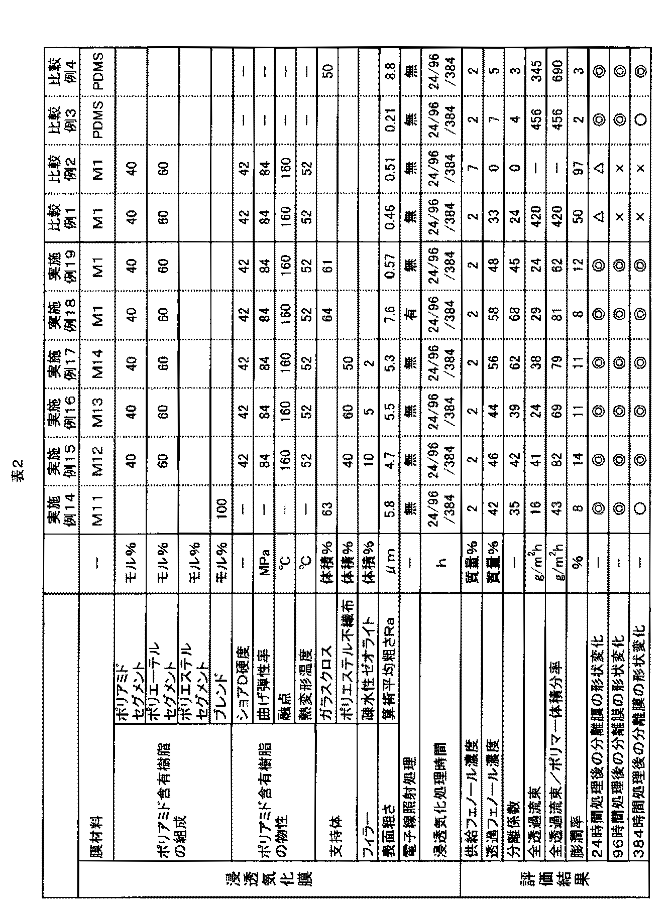
- Example 14 Except that the membrane material M1 was changed to the membrane material M11, an osmosis vaporization membrane was obtained in the same manner as in Example 1, and an osmosis vaporization treatment was performed on the phenol aqueous solution.
- the membrane material M11 is a blend material of nylon 12 (50 mol%) and polyethylene (50 mol%).
- Example 15 While changing the membrane material M1 to the membrane material M12 and changing the occupancy rate of the support, an osmosis vaporization membrane was obtained in the same manner as in Example 2, and the phenol aqueous solution was subjected to osmosis vaporization treatment.
- the membrane material M12 is obtained by adding a hydrophobic zeolite filler (average particle size 3 ⁇ m) to the membrane material M1. Moreover, the volume fraction of the filler in the pervaporation membrane was 10%.
- Example 16 While changing the membrane material M1 to the membrane material M13 and changing the occupancy rate of the support, an osmosis vaporization membrane was obtained in the same manner as in Example 2, and the phenol aqueous solution was subjected to osmosis vaporization treatment.
- the membrane material M13 is obtained by adding a hydrophobic zeolite filler (average particle size of 3 ⁇ m) to the membrane material M1. Moreover, the volume fraction of the filler in the pervaporation membrane was 5%.
- Example 17 While changing the membrane material M1 to the membrane material M14 and changing the occupancy rate of the support, an osmotic vaporized membrane was obtained in the same manner as in Example 2, and the phenol aqueous solution was subjected to an osmotic vaporization treatment.
- the membrane material M14 is obtained by adding a hydrophobic zeolite filler (average particle size 3 ⁇ m) to the membrane material M1. Moreover, the volume fraction of the filler in the pervaporation membrane was 2%.
- Example 18 The aqueous phenol solution was subjected to pervaporation treatment in the same manner as in Example 1 except that the permeation vaporized membrane produced in the same manner as in Example 1 was irradiated with an electron beam under the following conditions.
- Example 19 A pervaporation membrane was obtained in the same manner as in Example 1 except that a mirror-finished plate (made of stainless steel) was used as the backing plate of the press machine. The average thickness of the obtained pervaporation membrane was 130 ⁇ m.
- Example 2 The support is omitted, and a flat membrane made of polyamide-containing resin is used as the pervaporation membrane, and an aqueous solution (pH 8.0) having a phenol concentration of 7% by mass and an inorganic ionic impurity concentration of 1% by mass is used as the phenol aqueous solution. Except for the above, the phenol aqueous solution was subjected to pervaporation treatment in the same manner as in Example 1.
- Example 3 The phenol aqueous solution was subjected to pervaporation treatment in the same manner as in Example 1 except that a flat membrane having an average thickness of 100 ⁇ m made of polydimethylsiloxane (PDMS) was used as the pervaporation membrane.
- PDMS polydimethylsiloxane
- Example 4 The support used in Example 1 is embedded in a flat membrane made of polydimethylsiloxane (PDMS) so that the overall average thickness becomes 130 ⁇ m, and the resulting product is used as a pervaporation membrane.
- PDMS polydimethylsiloxane
- the phenol aqueous solution was subjected to pervaporation treatment in the same manner as in Example 1 except that.
- the flexural modulus was measured for the cured products of the polyamide-containing resin used in each example and each comparative example. Note that the flexural modulus of the polyamide-containing resin was measured by a measurement method defined in ISO 178. The thickness of the test piece was 100 ⁇ m, the width of the test piece was 10 mm, and the distance between fulcrums was 50 mm. Tables 1 and 2 show the measured flexural modulus.
- the heat distortion temperature was measured about the hardened
- the heat distortion temperature of the polyamide-containing resin was measured by a measurement method specified in ISO 75, and the pressure applied to the test piece was 0.46 MPa. Tables 1 and 2 show the measured heat distortion temperatures.
- the phenol concentration before the pervaporation treatment (hereinafter referred to as “supplied phenol concentration”) and the phenol concentration after the pervaporation treatment (hereinafter referred to as “permeated phenol concentration”) are respectively made by Shimadzu Corporation, capillary gas chromatograph system. It was measured using GC-2014.
- feed water concentration water concentration before the pervaporation treatment
- permeate concentration water concentration after the pervaporation treatment
- Total permeation flux Permeation / Effective area of pervaporation membrane
- ⁇ Evaluation criteria> No change (wrinkle, deflection, etc.) was observed in the appearance of the pervaporation membrane.
- ⁇ A change (wrinkle, deflection, etc.) was observed within the area ratio of the pervaporation membrane of 10% or less.
- ⁇ Pervaporation Change (wrinkle, deflection, etc.) was observed in the range of the membrane area ratio exceeding 10%.
- X Wrinkles, deflection, etc. were observed in the area ratio of the pervaporation membrane area exceeding 50%, or the pervaporation membrane was torn occured
- the pervaporation membrane obtained in each comparative example had a low concentration rate. Moreover, about the part of the pervaporation film
- the present invention relates to a pervaporation membrane used when a phenol in a liquid containing phenol, water and inorganic ions is concentrated by a pervaporation method, and covers a porous support and the support. And a coating layer made of a polyamide-containing resin.
Landscapes
- Chemical & Material Sciences (AREA)
- Chemical Kinetics & Catalysis (AREA)
- Organic Chemistry (AREA)
- Engineering & Computer Science (AREA)
- Water Supply & Treatment (AREA)
- Inorganic Chemistry (AREA)
- Life Sciences & Earth Sciences (AREA)
- Hydrology & Water Resources (AREA)
- Environmental & Geological Engineering (AREA)
- Separation Using Semi-Permeable Membranes (AREA)
- Organic Low-Molecular-Weight Compounds And Preparation Thereof (AREA)
- Treatments For Attaching Organic Compounds To Fibrous Goods (AREA)
Abstract
Description
(1) フェノールと水と無機イオンとを含む液体中のフェノールを、浸透気化法により濃縮する際に用いられる浸透気化膜であって、
多孔質の支持体と、前記支持体を覆うように設けられ、ポリアミド含有樹脂で構成された被覆層と、を備えることを特徴とする浸透気化膜。
本発明のフェノール濃縮方法は、本発明の浸透気化膜を用いた浸透気化法により、フェノールと水と無機イオンとを含む液体中のフェノールを濃縮するものであるが、この浸透気化法とは、例えば、液相と気相とが浸透気化膜により隔てられた状態で、液相側の溶質の分圧を駆動力として、溶質について優先的に浸透気化膜を透過させ、溶質を濃縮する方法である。このような浸透気化法は、浸透気化膜を備えた浸透気化分離装置により行う。
次いで、本発明の浸透気化膜の実施形態について説明する。
被覆層12は、支持体11を覆うように設けられた緻密質の層である。この被覆層12は、ポリアミド含有樹脂で構成されている。
下記式(1)は、ポリアミドセグメントの構造式の一例である。

本実施形態に係る浸透気化膜1は、支持体11を備えている。支持体11とは、浸透気化膜1の内部または表面に設けられ、膜構造を補強して全体の機械的強度を高めるものである。
図3(b)に示す浸透気化膜1は、被覆層12と、この被覆層12の一方の面に積層された支持体11と、を有している以外、図3(a)に示す浸透気化膜1と同様である。このような浸透気化膜1は、未硬化または未固化の被覆層12を支持体11の一方の面に載せ、加熱しつつ加圧する方法等により形成される。
また、浸透気化膜1は、必要に応じてフィラーを含んでいてもよい。フィラーとは、ポリアミド含有樹脂中に分散する粒子であり、浸透気化膜1の各種特性、例えば機械的特性を高めるよう作用する。
フィラーの形状としては、例えば、球状、板状(鱗片状)、針状等が挙げられる。
浸透気化膜1には、必要に応じて、電子線照射処理が施されていてもよい。電子線照射処理は、被覆層12等に対して電子線を照射することにより改質する処理である。前述したようなポリアミド含有樹脂で構成された被覆層12に対して電子線を照射すると、電子線のエネルギーによって被覆層12の表面はもとより被覆層12の層内にも改質が及ぶ。そして、層中のポリマーの架橋密度を高め、機械的強度を向上させる。その結果、膨潤しても劣化し難くなる等、浸透気化膜1の耐久性をより高めることができる。また、電子線照射処理によれば、有機物との親和性を担っているアミド結合等官能基や化学結合が消失したり変性を受けたりし難いと考えられる。このため、上述したようにして機械的強度の向上が図られる一方、有機物の分離特性はほとんど低下しない。特に長期間にわたって浸透気化のプロセスに供された場合であっても、有機物の分離特性が低下し難く、かつ破れ難いという点で、浸透気化膜1は有用である。さらに、電子線照射によって、膜の表面に官能基が導入され、被処理液との接触性が良好になる。その結果、有機物と膜との接触性も良好となり、有機物の分離特性が高められる。したがって、ポリアミド含有樹脂で構成された被覆層12に電子線照射処理を施すことによって、有機物の分離特性と耐久性とをとりわけ高度に両立させた浸透気化膜1が得られる。
次いで、本発明のフェノール濃縮方法の実施形態について説明する。上述した本発明の浸透気化膜は、各種有機物を含む液体を処理対象(被処理液)としているが、以下の説明では、フェノール水溶液が被処理液である場合について説明する。
図4に示すフェノール濃縮方法は、被処理液A1に前処理を施す前処理工程S1と、前処理が施された被処理液A2を浸透気化膜1を用いた浸透気化法に供し、被処理液A2中のフェノールを優先的に気化させる浸透気化工程S2と、気体状態の透過物A3を凝縮し、液体または固体状態の凝縮物A4を得る凝縮工程S3と、を有する。これらの工程を経ることにより、フェノールを濃縮した凝縮物A4を得ることができる。以下、各工程について詳述する。
前処理工程S1では、前述したように凝集剤を用いた沈降処理、濾過処理、逆浸透膜処理、共沸処理、蒸留処理等を行うことにより、被処理液A1中の異物を除去したり、被処理液A1の減容化を図る。このうち、逆浸透膜処理では、逆浸透膜(RO膜)を用いて被処理液A1中に含まれる水を除去し、フェノール濃度を高める。その結果、被処理液A1の減容化が図られることとなる。このような前処理を経て被処理液A2が得られる。
浸透気化工程S2では、被処理液A2を図2に示す浸透気化膜モジュール120の供給側空間122に供給する。この際、浸透気化膜モジュール120の透過側空間123を減圧する。これにより、被処理液A2中のフェノールが浸透気化膜1を優先的に透過する。この際、フェノールや水は気体状態になって透過し、気体状態の透過物A3が得られる。
凝縮工程S3では、気体状態の透過物A3を凝縮する。これにより、透過物A3が液化し、液体状態の凝縮物A4が得られる。また、凝縮条件によっては、固体状態の凝縮物A4が得られる。
また、上記フェノール濃縮方法は、フェノール以外の有機物に対しても適用可能である。
1.フェノール水溶液の濃縮
以下、各実施例および各比較例のようにして浸透気化膜を形成するとともに、フェノール水溶液を濃縮した。なお、各実施例および各比較例で得られた浸透気化膜の条件について、表1、2に示す。
(1)平膜の形成
まず、膜材料M1を200℃で加熱溶融し、得られた溶融物を押出法により平膜状に成膜した。これにより平膜を得た。なお、膜材料M1は、表1に示すセグメントを含むブロック共重合体である。
次いで、支持体としてガラスクロス(日東紡社製、WEA116E、質量105g/m2)を用意した。この支持体と前述の平膜とを重ね、プレス機にセットした。なお、プレス機においてプレス対象物に当接する上下の当て板には、それぞれシリコーンゴムシート(厚さ500μm)を用いた。そして、プレス機で、50kg/cm2の圧力で5分間加圧することにより、支持体と平膜とを圧着し、浸透気化膜を得た。得られた浸透気化膜の平均厚さは130μmであった。なお、浸透気化膜の平均厚さは、接触式のデジマチックインジケーターを用いて測定した。また、浸透気化膜においてポリアミド含有樹脂が占める占有率は36体積%であった。
次いで、製造した浸透気化膜を図1に示す浸透気化膜モジュールに取り付けた。そして、浸透気化膜モジュールの供給側空間にフェノール水溶液を供給した。なお、供給したフェノール水溶液は、フェノール濃度2質量%、無機イオン性不純物濃度1質量%の水溶液(pH8.5)とした。また、液温を60℃とした。
支持体を以下のものに変更した以外は、実施例1と同様にして浸透気化膜を得るとともに、フェノール水溶液に浸透気化処理を施した。
フェノール水溶液としてフェノール濃度7質量%、無機イオン性不純物濃度1質量%の水溶液(pH8.0)を用いるようにした以外は、実施例1と同様にしてフェノール水溶液に浸透気化処理を施した。また、支持体の占有率(体積分率)を表1に示す値になるよう変更した。
膜材料M1を膜材料M3に変更するとともに支持体の占有率(体積分率)が表1に示す値になるよう変更した以外は、実施例1と同様にして浸透気化膜を得るとともに、フェノール水溶液に浸透気化処理を施した。なお、膜材料M3は、表1に示すセグメントを含むブロック共重合体である。
膜材料M1を膜材料M4に変更するとともに支持体の占有率(体積分率)が表1に示す値になるよう変更ようにした以外は、実施例1と同様にして浸透気化膜を得るとともに、フェノール水溶液に浸透気化処理を施した。なお、膜材料M4は、表1に示すセグメントを含むブロック共重合体である。
膜材料M1を膜材料M5に変更するとともに支持体の占有率(体積分率)が表1に示す値になるよう変更ようにした以外は、実施例1と同様にして浸透気化膜を得るとともに、フェノール水溶液に浸透気化処理を施した。なお、膜材料M5は、表1に示すセグメントを含むブロック共重合体である。
膜材料M1を膜材料M6に変更するとともに支持体の占有率(体積分率)が表1に示す値になるよう変更ようにした以外は、実施例1と同様にして浸透気化膜を得るとともに、フェノール水溶液に浸透気化処理を施した。なお、膜材料M6は、表1に示すセグメントを含むブロック共重合体である。
膜材料M1を膜材料M7に変更するとともに支持体の占有率(体積分率)が表1に示す値になるよう変更ようにした以外は、実施例1と同様にして浸透気化膜を得るとともに、フェノール水溶液に浸透気化処理を施した。なお、膜材料M7は、表1に示すセグメントを含むブロック共重合体である。
膜材料M1を膜材料M8に変更するとともに支持体の占有率(体積分率)が表1に示す値になるよう変更ようにした以外は、実施例1と同様にして浸透気化膜を得るとともに、フェノール水溶液に浸透気化処理を施した。なお、膜材料M8は、表1に示すセグメントを含むブロック共重合体である。
膜材料M1を膜材料M9に変更するとともに支持体の占有率(体積分率)が表1に示す値になるよう変更ようにした以外は、実施例1と同様にして浸透気化膜を得るとともに、フェノール水溶液に浸透気化処理を施した。なお、膜材料M9は、表1に示すセグメントを含むブロック共重合体である。
膜材料M1を膜材料M10に変更するとともに支持体の占有率(体積分率)が表1に示す値になるよう変更ようにした以外は、実施例1と同様にして浸透気化膜を得るとともに、フェノール水溶液に浸透気化処理を施した。なお、膜材料M10は、表1に示すセグメントを含むブロック共重合体である。
支持体の占有率(体積分率)が表1に示す値になるよう変更した以外は、実施例1と同様にして浸透気化膜を得るとともに、フェノール水溶液に浸透気化処理を施した。
支持体の占有率(体積分率)が表1に示す値になるよう変更した以外は、実施例1と同様にして浸透気化膜を得るとともに、フェノール水溶液に浸透気化処理を施した。
膜材料M1を膜材料M11に変更するようにした以外は、実施例1と同様にして浸透気化膜を得るとともに、フェノール水溶液に浸透気化処理を施した。なお、膜材料M11は、ナイロン12(50モル%)とポリエチレン(50モル%)とのブレンド材である。
膜材料M1を膜材料M12に変更するとともに、支持体の占有率を変更するようにした以外は、実施例2と同様にして浸透気化膜を得るとともに、フェノール水溶液に浸透気化処理を施した。なお、膜材料M12は、膜材料M1に対して疎水性ゼオライトのフィラー(平均粒径3μm)を添加したものである。また、浸透気化膜におけるフィラーの体積分率は10%であった。
膜材料M1を膜材料M13に変更するとともに、支持体の占有率を変更するようにした以外は、実施例2と同様にして浸透気化膜を得るとともに、フェノール水溶液に浸透気化処理を施した。なお、膜材料M13は、膜材料M1に対して疎水性ゼオライトのフィラー(平均粒径3μm)を添加したものである。また、浸透気化膜におけるフィラーの体積分率は5%であった。
膜材料M1を膜材料M14に変更するとともに、支持体の占有率を変更するようにした以外は、実施例2と同様にして浸透気化膜を得るとともに、フェノール水溶液に浸透気化処理を施した。なお、膜材料M14は、膜材料M1に対して疎水性ゼオライトのフィラー(平均粒径3μm)を添加したものである。また、浸透気化膜におけるフィラーの体積分率は2%であった。
実施例1と同様にして製造した浸透気化膜に対して以下の条件で電子線を照射するようにした以外は、実施例1と同様にしてフェノール水溶液に浸透気化処理を施した。
・電子線の加速電圧:150kV
・吸収線量 :100kGy
プレス機の当て板として、鏡面処理を施したプレート(ステンレス鋼製)を用いるようにした以外、実施例1と同様にして浸透気化膜を得た。得られた浸透気化膜の平均厚さは130μmであった。
支持体を省略し、ポリアミド含有樹脂で構成された平膜を浸透気化膜として用いるようにした以外は、実施例1と同様にしてフェノール水溶液に浸透気化処理を施した。
支持体を省略し、ポリアミド含有樹脂で構成された平膜を浸透気化膜として用いるとともに、フェノール水溶液としてフェノール濃度7質量%、無機イオン性不純物濃度1質量%の水溶液(pH8.0)を用いるようにした以外は、実施例1と同様にしてフェノール水溶液に浸透気化処理を施した。
ポリジメチルシロキサン(PDMS)で構成された平均厚さ100μmの平膜を浸透気化膜として用いるようにした以外は、実施例1と同様にしてフェノール水溶液に浸透気化処理を施した。
ポリジメチルシロキサン(PDMS)で構成された平膜に、全体の平均厚さが130μmとなるように実施例1で用いた支持体を埋め込み、これにより得られたものを浸透気化膜として用いるようにした以外は、実施例1と同様にしてフェノール水溶液に浸透気化処理を施した。
2.1 ショアD硬度
各実施例および各比較例で用いたポリアミド含有樹脂の硬化物について、ショアD硬度を測定した。なお、ポリアミド含有樹脂のショアD硬度は、ISO 868に規定された測定方法により測定した。測定したショアD硬度を表1、2に示す。
各実施例および各比較例で用いたポリアミド含有樹脂の硬化物について、曲げ弾性率を測定した。なお、ポリアミド含有樹脂の曲げ弾性率は、ISO 178に規定された測定方法により測定した。また、試験片の厚さは100μm、試験片の幅は10mm、支点間距離は50mmとした。測定した曲げ弾性率を表1、2に示す。
各実施例および各比較例で用いたポリアミド含有樹脂の硬化物について、融点を測定した。なお、ポリアミド含有樹脂の融点は、ASTM D3418に規定された測定方法により測定した。測定した融点を表1、2に示す。
各実施例および各比較例で用いたポリアミド含有樹脂の硬化物について、熱変形温度を測定した。なお、ポリアミド含有樹脂の熱変形温度は、ISO 75に規定された測定方法により測定し、試験片に加える圧力は0.46MPaとした。測定した熱変形温度を表1、2に示す。
24時間の浸透気化処理により得られた濃縮液について、フェノール濃度を測定するとともに、分離係数および全透過流束を算出した。測定結果および算出結果を表1、2に示す。なお、24時間の浸透気化処理においては、6時間ごとに被処理液であるフェノール水溶液を交換するようにした。
全透過流束 = 透過量/浸透気化膜の有効面積
24時間の浸透気化処理に供された浸透気化膜について、その外観を目視により観察した。そして、以下の基準に基づき、観察結果を評価した。評価結果を表1、2に示す。
◎:浸透気化膜の外観に全く変化(シワ、撓み等)が認められなかった
○:浸透気化膜の面積率10%以下の範囲に変化(シワ、撓み等)が認められた
△:浸透気化膜の面積率10%超の範囲に変化(シワ、撓み等)が認められた
×:浸透気化膜の面積率50%超の範囲にシワ、撓み等が認められるか、浸透気化膜に破れが生じた
11 支持体
12 被覆層
100 浸透気化分離装置
110 被処理液タンク
115 供給管路
120 浸透気化膜モジュール
121 筐体
122 供給側空間
123 透過側空間
125 透過管路
126 排出管路
130 透過物回収タンク
140 不透過物貯留タンク
150 前処理モジュール
S1 前処理工程
S2 浸透気化工程
S3 凝縮工程
A1、A2 被処理液
A3 透過物
A4 凝縮物
Claims (7)
- フェノールと水と無機イオンとを含む液体中のフェノールを、浸透気化法により濃縮する際に用いられる浸透気化膜であって、
多孔質の支持体と、前記支持体を覆うように設けられ、ポリアミド含有樹脂で構成された被覆層と、を備えることを特徴とする浸透気化膜。 - 前記ポリアミド含有樹脂は、ポリアミドセグメントを含む共重合体である請求項1に記載の浸透気化膜。
- 前記共重合体は、さらにポリエーテルセグメントを含むものである請求項2に記載の浸透気化膜。
- 前記共重合体は、前記ポリアミドセグメントを10~90モル%の割合で含むブロック共重合体である請求項3に記載の浸透気化膜。
- 前記支持体は、織布または不織布である請求項1ないし4のいずれか1項に記載の浸透気化膜。
- 前記支持体は、ガラス繊維で構成されている請求項5に記載の浸透気化膜。
- 請求項1ないし6のいずれか1項に記載の浸透気化膜を用いた浸透気化法により、フェノールと水とを含む液体中のフェノールを濃縮することを特徴とするフェノール濃縮方法。
Priority Applications (5)
| Application Number | Priority Date | Filing Date | Title |
|---|---|---|---|
| US14/763,032 US20150367292A1 (en) | 2013-01-25 | 2014-01-20 | Pervaporation membrane and method for concentrating phenols |
| JP2014558557A JPWO2014115687A1 (ja) | 2013-01-25 | 2014-01-20 | 浸透気化膜およびフェノール濃縮方法 |
| EP14743074.8A EP2949385A4 (en) | 2013-01-25 | 2014-01-20 | PERVAPORATION MEMBRANE AND METHOD FOR CONCENTRATING PHENOL |
| BR112015017689A BR112015017689A2 (pt) | 2013-01-25 | 2014-01-20 | membrana de pervaporação e método para concentrar fenóis |
| CN201480005851.3A CN104936685B (zh) | 2013-01-25 | 2014-01-20 | 浸透气化膜和苯酚浓缩方法 |
Applications Claiming Priority (4)
| Application Number | Priority Date | Filing Date | Title |
|---|---|---|---|
| JP2013012301 | 2013-01-25 | ||
| JP2013-012301 | 2013-01-25 | ||
| JP2013-133154 | 2013-06-25 | ||
| JP2013133154 | 2013-06-25 |
Publications (1)
| Publication Number | Publication Date |
|---|---|
| WO2014115687A1 true WO2014115687A1 (ja) | 2014-07-31 |
Family
ID=51227478
Family Applications (1)
| Application Number | Title | Priority Date | Filing Date |
|---|---|---|---|
| PCT/JP2014/051007 Ceased WO2014115687A1 (ja) | 2013-01-25 | 2014-01-20 | 浸透気化膜およびフェノール濃縮方法 |
Country Status (7)
| Country | Link |
|---|---|
| US (1) | US20150367292A1 (ja) |
| EP (1) | EP2949385A4 (ja) |
| JP (1) | JPWO2014115687A1 (ja) |
| CN (1) | CN104936685B (ja) |
| BR (1) | BR112015017689A2 (ja) |
| TW (1) | TW201438812A (ja) |
| WO (1) | WO2014115687A1 (ja) |
Cited By (5)
| Publication number | Priority date | Publication date | Assignee | Title |
|---|---|---|---|---|
| KR20170102972A (ko) * | 2015-02-23 | 2017-09-12 | 도쿄 오카 고교 가부시키가이샤 | 액체의 정제 방법, 약액 또는 세정액의 제조 방법, 필터 미디어 및 필터 디바이스 |
| KR20180081121A (ko) * | 2015-11-10 | 2018-07-13 | 도쿄 오카 고교 가부시키가이샤 | 액체를 피정제물로 하는 정제 방법, 규소 화합물 함유액을 피정제물로 하는 정제 방법, 실릴화제 약액, 막형성용 재료 또는 확산제 조성물의 제조 방법, 필터 미디어, 및 필터 디바이스 |
| JP2019098211A (ja) * | 2017-11-29 | 2019-06-24 | 京セラ株式会社 | 炭素膜付き多孔質体 |
| JP2020146639A (ja) * | 2019-03-14 | 2020-09-17 | オルガノ株式会社 | 有機溶剤の脱水装置及び脱水方法 |
| WO2024070355A1 (ja) * | 2022-09-26 | 2024-04-04 | 日東電工株式会社 | 浸透気化膜 |
Families Citing this family (6)
| Publication number | Priority date | Publication date | Assignee | Title |
|---|---|---|---|---|
| WO2017004496A1 (en) * | 2015-07-01 | 2017-01-05 | 3M Innovative Properties Company | Polymeric ionomer separation membranes and methods of use |
| US11318421B2 (en) * | 2019-05-10 | 2022-05-03 | Xergy Inc. | Thin wall polyether block amide membrane tubing and module |
| WO2017094473A1 (ja) * | 2015-11-30 | 2017-06-08 | 帝人株式会社 | 複合膜の製造方法 |
| JP7367529B2 (ja) * | 2018-03-15 | 2023-10-24 | 東レ株式会社 | 流体分離膜 |
| JP6733093B1 (ja) * | 2019-05-09 | 2020-07-29 | 株式会社三井E&Sマシナリー | ゼオライト膜に供する被処理流体の処理方法 |
| US20220176321A1 (en) * | 2020-12-09 | 2022-06-09 | New Jersey Institute Of Technology | System and Process for Hybrid Membrane Distillation-Pervaporation |
Citations (5)
| Publication number | Priority date | Publication date | Assignee | Title |
|---|---|---|---|---|
| JPH04326929A (ja) * | 1991-04-25 | 1992-11-16 | Nitto Denko Corp | 分離膜 |
| JPH06296831A (ja) | 1993-04-15 | 1994-10-25 | Mitsui Eng & Shipbuild Co Ltd | フェノール含有排水の処理方法 |
| JPH07275676A (ja) * | 1994-03-23 | 1995-10-24 | Metallges Ag | 複合膜、その製造方法および使用方法 |
| JPH0824892A (ja) * | 1994-07-15 | 1996-01-30 | Nikka Chem Co Ltd | フェノール性化合物の分解処理方法 |
| JPH0857274A (ja) * | 1994-08-24 | 1996-03-05 | Nagayanagi Kogyo Kk | パーベーパレーション用膜状材 |
Family Cites Families (2)
| Publication number | Priority date | Publication date | Assignee | Title |
|---|---|---|---|---|
| US4806245A (en) * | 1986-10-14 | 1989-02-21 | Bend Research, Inc. | Pervaporation of phenols |
| DE3924501A1 (de) * | 1989-07-25 | 1991-01-31 | Geesthacht Gkss Forschung | Membran fuer die trennung fluessiger stoffgemische nach dem pervaporationsprinzip |
-
2014
- 2014-01-20 CN CN201480005851.3A patent/CN104936685B/zh not_active Expired - Fee Related
- 2014-01-20 US US14/763,032 patent/US20150367292A1/en not_active Abandoned
- 2014-01-20 BR BR112015017689A patent/BR112015017689A2/pt not_active IP Right Cessation
- 2014-01-20 JP JP2014558557A patent/JPWO2014115687A1/ja active Pending
- 2014-01-20 WO PCT/JP2014/051007 patent/WO2014115687A1/ja not_active Ceased
- 2014-01-20 EP EP14743074.8A patent/EP2949385A4/en not_active Withdrawn
- 2014-01-24 TW TW103102743A patent/TW201438812A/zh unknown
Patent Citations (5)
| Publication number | Priority date | Publication date | Assignee | Title |
|---|---|---|---|---|
| JPH04326929A (ja) * | 1991-04-25 | 1992-11-16 | Nitto Denko Corp | 分離膜 |
| JPH06296831A (ja) | 1993-04-15 | 1994-10-25 | Mitsui Eng & Shipbuild Co Ltd | フェノール含有排水の処理方法 |
| JPH07275676A (ja) * | 1994-03-23 | 1995-10-24 | Metallges Ag | 複合膜、その製造方法および使用方法 |
| JPH0824892A (ja) * | 1994-07-15 | 1996-01-30 | Nikka Chem Co Ltd | フェノール性化合物の分解処理方法 |
| JPH0857274A (ja) * | 1994-08-24 | 1996-03-05 | Nagayanagi Kogyo Kk | パーベーパレーション用膜状材 |
Non-Patent Citations (2)
| Title |
|---|
| MASAKAZU KONDO ET AL.: "Separation of phenol in aquenous solution by pervaporation using polyether-block-amides membranes incorporating polyester substrate", MEMBRANE, vol. 21, no. 6, 1 January 1997 (1997-01-01), pages 343 - 350, XP055269801 * |
| See also references of EP2949385A4 |
Cited By (8)
| Publication number | Priority date | Publication date | Assignee | Title |
|---|---|---|---|---|
| KR20170102972A (ko) * | 2015-02-23 | 2017-09-12 | 도쿄 오카 고교 가부시키가이샤 | 액체의 정제 방법, 약액 또는 세정액의 제조 방법, 필터 미디어 및 필터 디바이스 |
| KR102069428B1 (ko) * | 2015-02-23 | 2020-01-22 | 도쿄 오카 고교 가부시키가이샤 | 액체의 정제 방법, 약액 또는 세정액의 제조 방법, 필터 미디어 및 필터 디바이스 |
| US10576433B2 (en) | 2015-02-23 | 2020-03-03 | Tokyo Ohka Kogyo Co., Ltd. | Method for purifying liquid, method for producing chemical solution or cleaning solution, filter medium, and filter device |
| KR20180081121A (ko) * | 2015-11-10 | 2018-07-13 | 도쿄 오카 고교 가부시키가이샤 | 액체를 피정제물로 하는 정제 방법, 규소 화합물 함유액을 피정제물로 하는 정제 방법, 실릴화제 약액, 막형성용 재료 또는 확산제 조성물의 제조 방법, 필터 미디어, 및 필터 디바이스 |
| KR102072749B1 (ko) * | 2015-11-10 | 2020-02-03 | 도쿄 오카 고교 가부시키가이샤 | 액체를 피정제물로 하는 정제 방법, 규소 화합물 함유액을 피정제물로 하는 정제 방법, 실릴화제 약액, 막형성용 재료 또는 확산제 조성물의 제조 방법, 필터 미디어, 및 필터 디바이스 |
| JP2019098211A (ja) * | 2017-11-29 | 2019-06-24 | 京セラ株式会社 | 炭素膜付き多孔質体 |
| JP2020146639A (ja) * | 2019-03-14 | 2020-09-17 | オルガノ株式会社 | 有機溶剤の脱水装置及び脱水方法 |
| WO2024070355A1 (ja) * | 2022-09-26 | 2024-04-04 | 日東電工株式会社 | 浸透気化膜 |
Also Published As
| Publication number | Publication date |
|---|---|
| TW201438812A (zh) | 2014-10-16 |
| BR112015017689A2 (pt) | 2017-07-11 |
| CN104936685A (zh) | 2015-09-23 |
| US20150367292A1 (en) | 2015-12-24 |
| CN104936685B (zh) | 2017-02-22 |
| EP2949385A1 (en) | 2015-12-02 |
| JPWO2014115687A1 (ja) | 2017-01-26 |
| EP2949385A4 (en) | 2016-11-02 |
Similar Documents
| Publication | Publication Date | Title |
|---|---|---|
| WO2014115687A1 (ja) | 浸透気化膜およびフェノール濃縮方法 | |
| CN103842055B (zh) | 分离膜、分离膜元件及分离膜的制造方法 | |
| JP6206185B2 (ja) | 分離膜および分離膜エレメント | |
| CN102574069B (zh) | 复合半透膜的制造方法 | |
| KR20160078358A (ko) | 분리막 엘리먼트 | |
| KR20150035772A (ko) | 분리막 엘리먼트 | |
| TW201306927A (zh) | 分離膜、分離膜元件、及分離膜之製造方法 | |
| KR20130090759A (ko) | 분리막 엘리먼트 | |
| CN106457165B (zh) | 复合半透膜 | |
| KR20150035773A (ko) | 분리막 및 분리막 엘리먼트 | |
| KR20160108392A (ko) | 분리막, 시트 유로재 및 분리막 엘리먼트 | |
| JP2017047417A (ja) | 分離膜モジュール、分離膜エレメントおよびテレスコープ防止板 | |
| JP2015013256A (ja) | 浸透気化膜およびフェノール濃縮方法 | |
| JP2015167893A (ja) | 浸透気化膜およびフェノール濃縮方法 | |
| WO2018205823A1 (zh) | 一种反渗透膜及其制备方法 | |
| Fu et al. | Study on high-performance pervaporation desalination membranes prepared by interfacial reactions between two aqueous monomers | |
| JP2014159023A (ja) | 浸透気化膜およびフェノール濃縮方法 | |
| KR101737092B1 (ko) | 내산성이 우수한 폴리아마이드계 나노분리막 및 그 제조방법 | |
| JP2015013257A (ja) | 浸透気化膜およびフェノール濃縮方法 | |
| JP2015150545A (ja) | スパイラル型流体分離素子 | |
| JPWO2014208602A1 (ja) | 分離膜エレメント | |
| CN102186780A (zh) | 用于纯化来自费-托反应的含水物流的方法 | |
| JP2000288541A (ja) | スパイラル型逆浸透膜エレメントおよび分離方法 | |
| KR101526080B1 (ko) | 압력지연 삼투막 지지체용 부직포 및 이를 포함하는 압력지연 삼투막 | |
| JP2015142911A (ja) | 分離膜および分離膜エレメント |
Legal Events
| Date | Code | Title | Description |
|---|---|---|---|
| 121 | Ep: the epo has been informed by wipo that ep was designated in this application |
Ref document number: 14743074 Country of ref document: EP Kind code of ref document: A1 |
|
| ENP | Entry into the national phase |
Ref document number: 2014558557 Country of ref document: JP Kind code of ref document: A |
|
| REEP | Request for entry into the european phase |
Ref document number: 2014743074 Country of ref document: EP |
|
| WWE | Wipo information: entry into national phase |
Ref document number: 14763032 Country of ref document: US Ref document number: 2014743074 Country of ref document: EP |
|
| NENP | Non-entry into the national phase |
Ref country code: DE |
|
| REG | Reference to national code |
Ref country code: BR Ref legal event code: B01A Ref document number: 112015017689 Country of ref document: BR |
|
| ENP | Entry into the national phase |
Ref document number: 112015017689 Country of ref document: BR Kind code of ref document: A2 Effective date: 20150724 |