WO2014118830A1 - Structure de montage d'un réservoir de carburant sur la carrosserie du véhicule et dispositif destiné à éviter la déformation du réservoir de carburant - Google Patents
Structure de montage d'un réservoir de carburant sur la carrosserie du véhicule et dispositif destiné à éviter la déformation du réservoir de carburant Download PDFInfo
- Publication number
- WO2014118830A1 WO2014118830A1 PCT/JP2013/005635 JP2013005635W WO2014118830A1 WO 2014118830 A1 WO2014118830 A1 WO 2014118830A1 JP 2013005635 W JP2013005635 W JP 2013005635W WO 2014118830 A1 WO2014118830 A1 WO 2014118830A1
- Authority
- WO
- WIPO (PCT)
- Prior art keywords
- fuel tank
- band
- vehicle body
- coupled
- upper wall
- Prior art date
- Legal status (The legal status is an assumption and is not a legal conclusion. Google has not performed a legal analysis and makes no representation as to the accuracy of the status listed.)
- Ceased
Links
Images




Classifications
-
- B—PERFORMING OPERATIONS; TRANSPORTING
- B60—VEHICLES IN GENERAL
- B60K—ARRANGEMENT OR MOUNTING OF PROPULSION UNITS OR OF TRANSMISSIONS IN VEHICLES; ARRANGEMENT OR MOUNTING OF PLURAL DIVERSE PRIME-MOVERS IN VEHICLES; AUXILIARY DRIVES FOR VEHICLES; INSTRUMENTATION OR DASHBOARDS FOR VEHICLES; ARRANGEMENTS IN CONNECTION WITH COOLING, AIR INTAKE, GAS EXHAUST OR FUEL SUPPLY OF PROPULSION UNITS IN VEHICLES
- B60K15/00—Arrangement in connection with fuel supply of combustion engines or other fuel consuming energy converters, e.g. fuel cells; Mounting or construction of fuel tanks
- B60K15/03—Fuel tanks
- B60K15/063—Arrangement of tanks
- B60K15/067—Mounting of tanks
-
- B—PERFORMING OPERATIONS; TRANSPORTING
- B60—VEHICLES IN GENERAL
- B60K—ARRANGEMENT OR MOUNTING OF PROPULSION UNITS OR OF TRANSMISSIONS IN VEHICLES; ARRANGEMENT OR MOUNTING OF PLURAL DIVERSE PRIME-MOVERS IN VEHICLES; AUXILIARY DRIVES FOR VEHICLES; INSTRUMENTATION OR DASHBOARDS FOR VEHICLES; ARRANGEMENTS IN CONNECTION WITH COOLING, AIR INTAKE, GAS EXHAUST OR FUEL SUPPLY OF PROPULSION UNITS IN VEHICLES
- B60K15/00—Arrangement in connection with fuel supply of combustion engines or other fuel consuming energy converters, e.g. fuel cells; Mounting or construction of fuel tanks
- B60K15/03—Fuel tanks
- B60K15/063—Arrangement of tanks
- B60K2015/0634—Arrangement of tanks the fuel tank is arranged below the vehicle floor
-
- B—PERFORMING OPERATIONS; TRANSPORTING
- B60—VEHICLES IN GENERAL
- B60K—ARRANGEMENT OR MOUNTING OF PROPULSION UNITS OR OF TRANSMISSIONS IN VEHICLES; ARRANGEMENT OR MOUNTING OF PLURAL DIVERSE PRIME-MOVERS IN VEHICLES; AUXILIARY DRIVES FOR VEHICLES; INSTRUMENTATION OR DASHBOARDS FOR VEHICLES; ARRANGEMENTS IN CONNECTION WITH COOLING, AIR INTAKE, GAS EXHAUST OR FUEL SUPPLY OF PROPULSION UNITS IN VEHICLES
- B60K15/00—Arrangement in connection with fuel supply of combustion engines or other fuel consuming energy converters, e.g. fuel cells; Mounting or construction of fuel tanks
- B60K15/03—Fuel tanks
- B60K15/063—Arrangement of tanks
- B60K2015/0636—Arrangement of tanks the fuel tank being part of the chassis or frame
-
- B—PERFORMING OPERATIONS; TRANSPORTING
- B60—VEHICLES IN GENERAL
- B60K—ARRANGEMENT OR MOUNTING OF PROPULSION UNITS OR OF TRANSMISSIONS IN VEHICLES; ARRANGEMENT OR MOUNTING OF PLURAL DIVERSE PRIME-MOVERS IN VEHICLES; AUXILIARY DRIVES FOR VEHICLES; INSTRUMENTATION OR DASHBOARDS FOR VEHICLES; ARRANGEMENTS IN CONNECTION WITH COOLING, AIR INTAKE, GAS EXHAUST OR FUEL SUPPLY OF PROPULSION UNITS IN VEHICLES
- B60K15/00—Arrangement in connection with fuel supply of combustion engines or other fuel consuming energy converters, e.g. fuel cells; Mounting or construction of fuel tanks
- B60K15/03—Fuel tanks
- B60K15/063—Arrangement of tanks
- B60K15/067—Mounting of tanks
- B60K2015/0675—Mounting of tanks allowing deflection movements of the tank in case of a crash
-
- Y—GENERAL TAGGING OF NEW TECHNOLOGICAL DEVELOPMENTS; GENERAL TAGGING OF CROSS-SECTIONAL TECHNOLOGIES SPANNING OVER SEVERAL SECTIONS OF THE IPC; TECHNICAL SUBJECTS COVERED BY FORMER USPC CROSS-REFERENCE ART COLLECTIONS [XRACs] AND DIGESTS
- Y10—TECHNICAL SUBJECTS COVERED BY FORMER USPC
- Y10T—TECHNICAL SUBJECTS COVERED BY FORMER US CLASSIFICATION
- Y10T137/00—Fluid handling
- Y10T137/8593—Systems
- Y10T137/85978—With pump
Definitions
- the present invention relates to a fuel tank body mounting structure for mounting a fuel tank to a vehicle body, and a deformation preventing device for preventing deformation of the fuel tank.
- Patent Document 1 In order to attach the fuel tank to the vehicle body, a band is bridged in a groove formed on the surface of the fuel tank, both ends of the band are bolted to the vehicle body, and the surface of the fuel tank is pressed against the vehicle body by a rubber cushion and fixed.
- Patent Document 1 This configuration can suppress independent vibration of the fuel tank.
- a fixing member in which a metal screw member (for example, a nut) is embedded in a resin member in which a permeation-resistant resin and a welding / adhesive resin are integrally formed in multiple layers is welded to the upper surface of the fuel tank.
- Patent Document 3 A configuration in which a tank is attached to a vehicle body is known (Patent Document 3). According to Patent Document 3, the fuel tank can be firmly attached to the vehicle body by this configuration.
- the mounting structure is for attaching an accessory such as a protector to the outside of the fuel tank.
- the recess is formed on the surface of the fuel tank, the accessory having a through hole and attached to the outside of the fuel tank, and the fuel tank.
- Patent Document 4 There is known a configuration in which the second fastener is inserted through a through hole and engaged with a claw provided on the inner periphery of the recess.
- Patent Document 4 According to Patent Document 4, according to this configuration, the accessory part can be attached to the fuel tank only by providing a recess on the surface of the fuel tank.
- the fuel tank In a typical front engine passenger car, the fuel tank is often mounted horizontally under the floor near the rear seat. This is to avoid damage caused by a collision and to reduce the influence of the amount of fuel on the position of the center of gravity of the vehicle body and the moment of inertia of the vehicle body.
- the fuel tank is exposed to changes in the outside air temperature and temperature changes due to the heat of the exhaust.
- the material of the fuel tank has changed from steel plate to resin. This is because resin tanks have a penetration and fracture strength that is slightly inferior to those of steel plates, but they are light in weight without generating rust and have the advantage that they can be mass-produced at low cost even with complex shapes.
- the fuel tank is negatively charged as the pump module transports gasoline from the fuel tank.
- the phenomenon that becomes pressure is known. If the discharge force of the pump module is increased with the adoption of an electronically controlled fuel injection device or the like, fuel may be forcibly discharged even if the fuel tank becomes negative pressure, and the fuel tank may be damaged.
- An object of the present invention is to provide a vehicle body mounting structure for a fuel tank and a fuel tank deformation prevention tool capable of preventing harmful deformation that hinders the function of the fuel tank.
- the present invention is a vehicle tank mounting structure for a fuel tank, which is fixed to the vehicle body and extends along at least a lower wall (19L) of the fuel tank (1) to hold the fuel tank.
- a fuel tank vehicle body mounting structure comprising upper wall coupling means (40) for coupling at least one of the upper walls of the fuel tank to the holding member.
- the holding member extends along the upper wall (19U) of the fuel tank (1) and cooperates with the band lower (10L) to surround the fuel tank (10U).
- the upper wall coupling means (40) is configured to couple the upper wall of the fuel tank to the band upper.
- the cooperation of the band lower and the band upper makes it possible to prevent the fuel tank from being deformed even when the internal pressure of the fuel tank changes to either positive pressure or negative pressure.
- the fuel tank (1) is a resin tank having a recess (32) formed on a surface thereof, and the lower wall coupling means (40) and the upper wall coupling means (40) In this embodiment, a coupled member (41) fixed to the surface of the fuel tank is included.
- the strength of the fuel tank itself is improved by the recesses to prevent the deformation of the fuel tank, and the coupled member does not protrude greatly from the surface of the fuel tank. Therefore, even if the band lower and the band upper are included, the fuel tank The height of the vehicle body attachment structure can be kept low, and the fuel tank can be compactly attached to the vehicle body.
- the coupled member (41) includes an insert bolt (42b) or an insert nut provided integrally by insert molding, and a nut (44) screwed into the insert bolt (42b) or the insert nut. Or it is comprised so that a volt
- the band lower (10L) and the band upper (10U) are provided with the insert bolt (42b) or a through hole through which the bolt is inserted, and the size of the through hole includes the insert to be inserted.
- a predetermined play is set at least in the extending direction of the band lower and the band upper with respect to the bolt (42b) or the outer diameter of the bolt.
- the band lower and the band upper are made of resin and made of metal. It is possible to absorb a difference in linear expansion coefficient (that is, a difference in thermal expansion) such as a band lower.
- the lower wall coupling means (40) couples the lower wall (19L) of the fuel tank (1) to the band lower (10L) in a non-contact manner via the coupled member (41).
- the upper wall coupling means (40) is configured to couple the upper wall of the fuel tank in a non-contact manner with the band upper (10U) through the coupled member.
- the band lower (10L) and the band upper (10U) have flange portions (18) overlapping each other at their end portions, and the band lower and the band upper are attached to the vehicle body by the flange portions. It is configured to be fixed.
- the flange portion (18) is provided with a long hole whose major axis is the extending direction of the band lower (10L) and the band upper (10U), and the flange portion is arranged in a direction along the vehicle body. It is slidable.
- a pump module for sending fuel is joined to the upper wall (19U) of the fuel tank (1), and a plurality of upper wall coupling means (40) are provided in the vicinity of the pump module. Is.
- the cross section orthogonal to the extending direction of the band lower (10L) and the band upper (10U) is formed into a substantially hat shape.
- the present invention also provides a plurality of coupled members (41) provided on the surface of the fuel tank (1) and a plurality of bands (coupled to the coupled members and provided along the surface of the fuel tank ( 10), and a fuel tank deformation preventing device configured to connect the plurality of bands so that the plurality of bands make at least one round of the fuel tank along the surface of the fuel tank. .
- the band (10) extends along the lower wall (19L) of the fuel tank and holds the fuel tank (1), and the upper wall (10L) of the fuel tank ( 19U) and a band upper (10U) surrounding the fuel tank in cooperation with the band lower, and the coupled member (41) is at least one of the lower wall of the fuel tank
- the band upper has flange portions (18) that overlap each other at the end portion, and the band lower and the band upper are connected by the flange portion.
- the band lower and the band upper connected by the flange portion cooperate to prevent deformation of the fuel tank even when the internal pressure of the fuel tank changes to either positive pressure or negative pressure. It becomes possible.
- the fuel tank (1) is a resin tank having a recess (32) formed on a surface thereof, and the member to be coupled (41) is disposed in the recess.
- the strength of the fuel tank itself is improved by the recesses to prevent the deformation of the fuel tank, and the coupled member does not protrude greatly from the surface of the fuel tank. Therefore, even if the band lower and the band upper are included, the fuel tank The height of the deformation preventing tool can be kept low, and a compact configuration can be achieved.
- the coupled member (41) includes an insert bolt (42b) or an insert nut provided integrally by insert molding, and a nut (44) or a bolt that is screwed to the insert bolt or the insert nut. It is configured to include.
- the band lower (10L) and the band upper (10U) are provided with the insert bolt (42b) or a through hole through which the bolt is inserted, and the size of the through hole includes the insert to be inserted.
- a predetermined play is set at least in the extending direction of the band lower and the band upper with respect to the bolt (42b) or the outer diameter of the bolt.
- the band lower and the band upper are made of resin and made of metal. It is possible to absorb a difference in linear expansion coefficient (that is, a difference in thermal expansion) such as a band lower.
- the lower wall coupling means (40) couples the lower wall (19L) of the fuel tank (1) to the band lower (10L) in a non-contact manner via the coupled member (41).
- the upper wall coupling means (40) is configured to couple the upper wall (19U) of the fuel tank in a non-contact manner with the band upper (10U) through the coupled member.
- the fuel tank (1) is attached to the vehicle body via the flange portion (18).
- a pump module for sending fuel is joined to the upper wall (19U) of the fuel tank (1), and a plurality of upper wall coupling means (40) are provided in the vicinity of the pump module. Is.
- one of the lower wall coupling means (40) is configured such that the band lower (10L) is connected to the lower wall (10U) at a position facing the position where the pump module is joined on the upper wall (19U). 19L).
- the cross section orthogonal to the extending direction of the band lower (10L) and the band upper (10U) is formed into a substantially hat shape.
- the present invention it is possible to prevent deformation of the fuel tank even when the internal pressure of the fuel tank changes to either positive pressure or negative pressure, and to prevent destruction of equipment and the fuel tank built in the fuel tank. Is possible.
- 1 is a perspective view showing a vehicle tank mounting structure for a fuel tank according to a first embodiment of the present invention, and an overall configuration of the fuel tank.
- the top view which shows the vehicle body mounting structure of the fuel tank which concerns on 1st Embodiment of this invention.
- the bottom view which shows the vehicle body mounting structure of the fuel tank which concerns on 1st Embodiment of this invention
- Fig. 3 is a cross-sectional view showing the main part of the VII-VII cross section in Fig.
- FIG. 3 (A), (b) is a top view which shows the structure of area
- (A), (b), (c) are the principal part sectional drawings which show the principal part of the XX cross section of FIG. Sectional drawing which shows the outline of the vehicle body mounting structure of the fuel tank which concerns on 2nd Embodiment of this invention
- directions are expressed as front, back, left, right, up, and down based on the recognition of the driver who gets in the driver's seat of the car.
- the left-right direction may be expressed as the vehicle width direction.
- FIG. 1 is a top view showing a fuel tank 1 attached to a vehicle body in the first embodiment of the present invention.
- the fuel tank 1 is located under the floor near the rear seat, and is arranged such that its longitudinal direction is the vehicle width direction and its short direction is the front-rear direction.
- the body frame of an automobile includes a pair of left and right rear side frames 2, 2, and the first cross member 3, the second cross member 4, and the rear side frames 2, 2 extend in the vehicle width direction.
- the third cross member 5 is connected.
- the fuel tank 1 is disposed between the first cross member 3 and the second cross member 4.
- a band upper 10 ⁇ / b> U is bridged along the upper wall 19 ⁇ / b> U of the fuel tank 1.
- the band lower 10 ⁇ / b> L is bridged along the lower wall 19 ⁇ / b> L (see FIG. 4) of the fuel tank 1.
- the band upper 10U and the band lower 10L may be collectively referred to as the band 10).
- the fuel tank 1 is attached to the vehicle body via the band 10.
- the front end of the band 10 spanned in the front-rear direction is fixed to the first cross member 3 at two positions P5 and P6, and the rear end is fixed to the second cross member 4 at two positions P2 and P3. It is fixed.
- the left end and the right end of the band 10 spanned in the left-right direction are fixed to the rear side frames 2 and 2 by P1 and P4, respectively.
- the band upper 10U and the band lower 10L are both fixed to the vehicle body side and constitute a holding member for holding the fuel tank 1.
- a canister 12 is provided between the second cross member 4 and the third cross member 5.
- Gasoline which is a fuel for automobiles, has high volatility and is vaporized in the fuel tank 1 to become gasoline vapor. When this gasoline vapor is discharged into the atmosphere, it combines with oxygen and nitrogen compounds to turn into harmful substances.
- the canister 12 is mounted between the fuel tank 1 and an engine (not shown), and prevents the discharge of gasoline vapor that causes air pollution.
- a cut-off valve (not shown) is joined to the fuel tank 1 at a portion indicated as a cut-off valve mounting position 15.
- the cut-off valve normally has a valve body that discharges gasoline vapor generated in the fuel tank 1 and blocks fuel leakage when the vehicle body is reversed.
- the cut-off valve and the canister 12 are vented. It communicates with a tube (not shown).
- the gasoline vapor discharged from the cut-off valve side is adsorbed by activated carbon or the like filled in the canister 12.
- FIG. 1 shows the work in progress in the manufacturing process for the sake of simplicity, but the final product is provided with a mounting flange (not shown) that detachably covers the opening 17, and a stay (FIG.
- the pump module is supported via (not shown).
- a feed pipe (not shown) is connected to the engine (not shown) from the pump module through the mounting flange.
- FIG. 2 is a perspective view showing a vehicle body mounting structure of the fuel tank 1 according to the first embodiment of the present invention and the entire configuration of the fuel tank 1
- FIG. 3 is a diagram of the fuel tank 1 according to the first embodiment of the present invention. It is a top view which shows a vehicle body attachment structure.
- the configuration of the band 10 surrounding the fuel tank 1, in particular, the band upper 10 ⁇ / b> U spanned on the upper wall 19 ⁇ / b> U of the fuel tank 1 will be described in detail with reference to FIGS. 2 and 3.
- the fuel tank 1 has an upper wall 19U and a lower wall 19L.
- the upper wall 19U and the lower wall 19L may not be clearly distinguished. Therefore, here, when the fuel tank 1 is divided into two in the vertical direction, the wall constituting the upper side is It is referred to as a wall 19U, and a wall constituting the lower side is referred to as a lower wall 19L.
- the upper wall 19 ⁇ / b> U or the lower wall 19 ⁇ / b> L may simultaneously form the side wall of the fuel tank 1.
- two band uppers 10UR and 10UL are bridged over the upper wall 19U of the fuel tank 1 in the front-rear direction.
- the two band uppers 10UR and 10UL are disposed so as to be inclined from the rear to the front of the fuel tank 1 so that the distance between the two in the vehicle width direction gradually decreases.
- the band upper 10URR is joined to the right band upper 10UR by welding at a substantially central portion in the front-rear direction of the fuel tank 1, and the band upper 10URR extends from the joined portion toward the right side of the vehicle body. Yes.
- the band upper 10UL is joined to the left band upper 10UL by welding, and the band upper 10ULL extends from the joined portion toward the left side of the vehicle body.
- a band upper 10US that connects these two band uppers 10UR and 10UL in the vehicle width direction is joined to a substantially central portion in the front-rear direction of the band upper 10UR and the band upper 10UL by welding.
- the band upper 10US is disposed so as to surround the opening 17 in the vicinity of the opening 17 at the pump module mounting position 16. That is, the band upper 10US has an annular shape surrounding the opening 17 in a top view.
- the band uppers 10UR, 10UL, 10URR, 10ULL, and 10US may be collectively referred to as a band upper 10U.
- the band uppers 10UR, 10UL, 10URR, 10ULL, and 10US are joined together by welding to form an integral body.
- the band upper 10U is handled as one member.
- the band upper 10U is coupled to the upper wall 19U of the fuel tank 1. Specifically, the band upper 10UR is in PU3, the band upper 10URR is in PU1 and PU2, the band upper 10UL is in PU6, the band upper 10UL is in PU7 and PU8, and the band upper 10US is in PU4 and PU6 above the fuel tank 1. It couple
- the band upper 10US surrounds the opening 17 of the pump module mounting position 16, and the upper wall 19U of the fuel tank 1 and the band upper 10US are located very close to the pump module mounting position 16 (PU4, PU5). Join with.
- the deformation of the fuel tank 1 is prevented particularly near the pump module mounting position 16, and the pump module and its peripheral mechanism (not shown) can be prevented from being destroyed.
- At least one place (either one of PU4 and PU5) of the upper wall 19U is coupled to a holding member (band upper 10U) that holds the fuel tank 1 on the vehicle body. Deformation is prevented locally, and destruction of the device built in the fuel tank 1 is prevented.
- buffer members 20 are provided at two positions near the front and rear, respectively.
- a buffer member 21 is provided at the center in the vehicle width direction of the fuel tank 1 and at the rear in the front-rear direction.
- the buffer member 20 is mainly composed of an elastic body such as rubber, and includes a convex portion (not shown) protruding downward at the center thereof.
- the buffer member 20 is attached to the fuel tank 1 by fitting the convex portion into a concave portion (not shown) provided on the upper wall 19U.
- the buffer member 21 is a rubber member having an uneven surface, and is bonded to an approximately middle position between the cut-off valve mounting position 15 and the pump module mounting position 16 on the upper wall 19U using an adhesive. .
- the buffer member 20 may have the same configuration as the above-described upper wall coupling means, and in addition to this, an elastic body may be disposed on the vehicle body side.
- FIG. 4 is a bottom view showing the vehicle body mounting structure of the fuel tank 1 according to the first embodiment of the present invention.
- two band lowers 10LR and 10LL are bridged in the front-rear direction.
- the two band lowers 10LR and 10LL are arranged so as to be inclined from the rear to the front of the fuel tank 1 so that the distance between the two in the vehicle width direction gradually decreases.
- a band lower 10LRR is joined to the right band lower 10LR by welding at a substantially central portion in the front-rear direction of the fuel tank 1, and the band lower 10LRR extends from the joined portion toward the right side of the vehicle body.
- the band lower 10LLL is joined to the left band lower 10LL by welding, and the band lower 10LLL extends from the joining portion toward the left side of the vehicle body.
- a band lower 10LS that connects these two band lowers 10LR and 10LL in the vehicle width direction is joined to the substantially central portion in the front-rear direction of the band lower 10LR and the band lower 10LL by welding.
- the band lower 10LS extends in the vehicle width direction at a position just behind the pump module mounting position 16 provided on the upper wall 19U of the fuel tank 1.
- the band lowers 10LR, 10LL, 10LRR, 10LLL, and 10LS may be collectively referred to as the band lower 10L.
- the band lower 10L is also joined together by welding similarly to the band upper 10U, and the band lower 10L is handled as one member in the vehicle body mounting structure of the fuel tank 1.
- the band lower 10L is coupled to the lower wall 19L of the fuel tank 1.
- the band lower 10LR is PL6, PL7
- the band lower 10LR is PL8, PL9
- the band lower 10LL is PL3, PL4
- the band lower 10LLL is PL1, PL2
- the band lower 10LS is PL5, and the lower wall 19L of the fuel tank 1.
- the band lower 10LS is just behind the pump module mounting position 16 and extends in the vehicle width direction. Then, the lower wall 19L of the fuel tank 1 and the band lower 10LS are coupled to each other just behind the pump module mounting position 16 (PL5). This prevents the fuel tank 1 from being deformed, particularly in the vicinity of the pump module mounting position 16, and can prevent the pump module and its peripheral mechanism (not shown) from being damaged.
- At least one portion of the lower wall 19L is coupled to a holding member (band lower 10L) that holds the fuel tank 1 on the vehicle body, so that deformation of the fuel tank 1 is locally prevented, and the fuel tank 1 is prevented from being destroyed.
- a holding member band lower 10L
- FIG. 5 is a side view showing the vehicle body mounting structure of the fuel tank 1 according to the first embodiment of the present invention.
- the end of the band upper 10U spanned along the upper wall 19U of the fuel tank 1 and the end of the band lower 10L spanned along the lower wall 19L are P3, P4. , P5 overlap with each other to form the flange portion 18.
- the rear ends of the band upper 10UL and the band lower 10LL overlap at P3, the ends of the band upper 10ULL and the band lower 10LLL overlap at P4, and the front ends of the band upper 10UR and the band lower 10LR overlap at P5.
- These overlapping portions constitute the flange portion 18.
- FIG. 5 shows the left side of the fuel tank 1, but on the right side of the fuel tank 1, the ends of the band upper 10URR and the band lower 10LRR overlap at P1, and the band upper at P2.
- the rear ends of 10UR and the band lower 10LR are overlapped, and the front ends of the band upper 10UR and the band lower 10LR are overlapped at P6 (see FIGS. 3 and 4), and these overlapping portions constitute the flange portion 18.
- the overlapping band upper 10 ⁇ / b> U and band lower 10 ⁇ / b> L are fixed to the vehicle body by the flange portion 18. Further, the band upper 10 ⁇ / b> U and the band lower 10 ⁇ / b> L are connected at the flange portion 18 so that the entire circumference of the fuel tank 1 is surrounded by the band 10.
- FIG. 6 is an explanatory diagram for explaining a manufacturing process of the fuel tank 1.
- the fuel tank 1 is manufactured by blow molding using a resin material and has a multilayer (three layers) structure in the thickness direction.
- the manufacturing process of the fuel tank 1 will be described.
- the blow molding apparatus 22 for blow molding the fuel tank 1 includes first to third extruders 23a, 23b, 23c for extruding molten resin, and first to third extruders 23a, 23b, First to third dies 24a, 24b, and 24c connected to 23c, and a blow molding die 25 arranged below the first to third dies 24a, 24b, and 24c, respectively.
- the resin material extruded from the first extruder 23a constitutes the innermost layer of the fuel tank 1
- the resin material extruded from the third extruder 23c constitutes the outermost layer of the fuel tank 1, from the second extruder 23b.
- the extruded material constitutes the intermediate layer of the fuel tank 1.
- the resin material extruded from the 1st extruder 23a and the 3rd extruder 23c is the same, Comprising:
- a high density polyethylene is used.
- the resin material extruded from the second extruder 23b may be, for example, a material in which a fine sheet-like polyamide sheet material is mixed into high-density polyethylene in order to form a barrier layer.
- the blow molding die 25 includes a first half 25a and a second half 25b that can be freely opened and closed.
- a pin hole 28 for inserting an air pin 27 into the cavity 26 is formed in the first half body 25a. Air is supplied to the air pin 27 from an air supply source 29.
- the molten resin extruded from the first to third extruders 23a, 23b, 23c is used for the first to third dies 24a, 24b, 24c. Is formed, and a three-layer cylindrical parison 100 is formed, and the parison 100 is sandwiched between the first and second halves 25a and 25b of the blow molding die 25. Subsequently, as shown in FIG. 6B, by inserting an air pin 27 into the pin hole 28 of the first half 25a and piercing the parison 100, and supplying air from the air supply source 29 into the parison 100, The parison 100 is expanded and brought into close contact with the wall surface of the cavity 26.
- the fuel tank 1 is molded by separating the first half 25a and the second half 25b.
- the inner surface shape of the fuel tank 1 is not regulated, but the outer surface shape is determined solely by the mold, and it is complicated by increasing the dimensional accuracy of the mold or appropriately setting the surface roughness.
- the fuel tank 1 having a shape can be manufactured with a predetermined surface roughness.
- a recess 32 (see FIG. 7) provided on the surface of the fuel tank 1 to be described later can also be easily formed by this process.
- FIG. 7 is a cross-sectional view showing the main part of the VII-VII cross section of FIG.
- FIG. 7 shows a cross section orthogonal to the extending direction D1 of the band upper 10URR for the portion shown as region A1 in FIG.
- the specific configuration of the upper wall coupling means and the lower wall coupling means in the first embodiment will be described in detail with reference to FIG.
- the difference between the upper wall coupling means for coupling the upper wall 19U of the fuel tank 1 to the band upper 10U and the lower wall coupling means for coupling the lower wall 19L of the fuel tank 1 to the band lower 10L is simply the upper and lower portions of the fuel tank 1. Therefore, in the following description, the upper wall coupling means provided mainly on the upper wall 19U will be described, and the upper wall coupling means will be simply referred to as the coupling means 40. I will explain.
- the fuel tank 1 has a three-layer structure in the thickness direction, and a high-density polyethylene layer 30, a polyamide sheet mixed layer (barrier layer) 31, and a high-density polyethylene layer 30 are laminated in order from the inside. ing.
- the high density polyethylene layer 30 is excellent in mechanical strength
- the polyamide sheet mixed layer 31 is excellent in the barrier properties of hydrocarbons such as gasoline and alcohol.
- the coupling means 40 includes, for example, a coupled member 41 in which an insert bolt 42b is insert-molded in a high-density polyethylene base 42a, and a washer 43 that is screwed to the insert bolt 42b to couple the coupled member 41 to the band upper 10U. And a nut 44.
- the coupled member 41 has a structure in which the shaft of the insert bolt 42b protrudes from the base 42a.
- the description will be made on the assumption that the insert bolt 42b is provided on the base 42a of the member 41 to be coupled.
- an insert nut (not shown) is insert-molded on the base 42a, and the member 41 is coupled.
- the band upper 10U may be coupled by a washer 43 and a bolt (not shown) (the same applies to the second embodiment).
- the bolt is tightened after the band upper 10U is attached. Therefore, if the tightening torque becomes too large, the shaft of the bolt may damage the fuel tank 1, and the tightening torque Should be managed more appropriately.
- the to-be-coupled member 41 is fixed to the bottom surface of the concave portion 32 whose side surface provided on the upper wall 19U of the fuel tank 1 has a tapered shape by heat welding. Providing the recess 32 in the fuel tank 1 improves the mechanical strength of the fuel tank 1 itself.
- the member 41 to be coupled is fixed to the bottom surface of the recess 32 so that the member 41 does not protrude significantly from the upper wall 19U of the fuel tank 1, and even if the band upper 10U is coupled thereto, the fuel tank Thus, the height of the entire vehicle body mounting structure 1 can be kept low, and the fuel tank 1 can be mounted compactly on the vehicle body.
- the material of the outermost layer of the member 41 and the fuel tank 1 are both high-density polyethylene, the same material is bonded extremely firmly at the molecular level by heat welding. Further, instead of heat welding, high frequency welding or ultrasonic welding may be used. Regardless of the method, both are firmly bonded at the molecular level.
- the member to be coupled 41 may be fixed to the fuel tank 1 using, for example, an adhesive.
- the band upper 10U is obtained, for example, by press forming a cold rolled steel sheet having a tensile strength of 270 N / mm 2 or more. However, individual parts constituting the above-described band upper 10U are obtained by press molding (see FIGS. 2 and 3). The final band upper 10U is completed by welding and connecting these parts. Of course, you may make it manufacture the band upper 10U collectively by press molding.
- the cross section of the band upper 10U has a so-called hat shape, and ensures rigidity against bending stress.
- the upper wall coupling means (lower wall coupling means) 40 is a member to be coupled 41 provided on the upper wall 19U (lower wall 19L) of the fuel tank 1.
- the band upper 10U (band lower 10L) itself has high rigidity, and such a highly rigid member surrounds the entire circumference of the fuel tank 1, so that the fuel tank 1 does not expand or contract due to a change in internal pressure. The deformation is regulated from the outside.
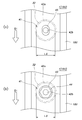
- FIG. 8A and 8B are top views showing the configuration of the region A1 in FIG.
- FIG. 8A shows a state in which the band upper 10U is placed on the member to be coupled 41 constituting the coupling means 40
- FIG. 8B shows the state of the member 41 to be coupled from the state of FIG.
- the state where the washer 43 and the nut 44 are attached to the insert bolt 42b, that is, the state where the fuel tank 1 (here, the upper wall 19U) is coupled to the band upper 10U is shown.
- the band upper 10U hides the configuration below the band upper 10U, so that the recess 32, the coupled member 41, and the base 42a provided on the surface of the fuel tank 1 are used. Is drawn as an imaginary line (two-dot chain line).
- the band upper 10U is provided with a through hole 45 for inserting the insert bolt 42b.
- the through hole 45 is a long hole having a long diameter in the extending direction D1 of the band upper 10U.
- the band upper 10U through which the insert bolt 42b is inserted is fastened to the coupled member 41 by a washer 43 and a nut 44, whereby the upper wall of the fuel tank 1 is secured.
- 19U is coupled to the band upper 10U.
- the tightening torque is managed so that the coupled member 41 and the band upper 10U are adjusted so as to be relatively displaceable along the surface of the fuel tank 1.
- the fuel tank 1 is allowed to be deformed along the extending direction of the band upper 10U within a range regulated by the through hole 45 which is a long hole.
- the linear expansion coefficient of polyethylene constituting the fuel tank 1 is 12 to 14 ⁇ 10 ⁇ 5 / ° C.
- the linear expansion coefficient of the metal constituting the band upper 10U is, for example, 1.17 ⁇ 10 ⁇ 5 / ° C. for a cold-rolled steel plate and 0.9 ⁇ 10 ⁇ 5 / ° C. for a nickel steel.
- the amount of deformation increases in the circumferential direction (the longer the length over which the band upper 10U is bridged, the larger the amount of deformation), and the direction in which deformation occurs (here, the band upper 10U mainly extends). If the fuel tank 1 is constrained at a plurality of positions in the direction), stress strain occurs between the constraining points. Therefore, in the first embodiment, the diameter of the through hole 45 provided in the band upper 10U is configured to be long in the extending direction of the band upper 10U, and the relative displacement between the two is allowed in the through hole 45, thereby making the material The difference between the linear expansion coefficients based on the difference is absorbed.
- the flange part 18 mentioned above is provided with the through-hole which is not shown in figure which attaches the fuel tank 1 to a vehicle body.
- the through-hole of the flange part 18 is also a long hole which makes the extending direction of the band upper 10U a long diameter.
- the band upper 10U suppresses deformation in the thickness direction of the fuel tank 1, such as expansion / contraction caused by a change in the internal pressure of the fuel tank 1, while expansion caused by a difference in linear expansion coefficient between the fuel tank 1 and the band upper 10U. -Eliminate stress strain due to shrinkage.
- a metal one can be used, but instead, for example, a highly slidable washer made of nylon or polytetrafluoroethylene is used (or used in combination with a metal washer). You may comprise so that the band upper 10U may be inserted
- the through hole 45 is elongated in the extending direction of the band upper 10U.
- the deformation of the fuel tank 1 and the band upper 10U due to thermal expansion is grasped by simulation or the like.
- the major and minor diameters of the through hole 45 provided in the band upper 10U may be set.
- FIG. 9 (a) and 9 (b) are cross-sectional views for explaining another configuration example of the coupling means 40.
- FIG. 9 (a) and 9 (b) are cross-sectional views for explaining another configuration example of the coupling means 40.
- the coupled member 41 constituting the coupling means 40 is fixed to the recess 32 provided on the surface of the fuel tank 1, but in FIG. 9A, the coupled member 41 is the fuel tank 1. It is welded to the flat surface.
- the parison 100 is pressed against the blow mold 25 to perform resin molding (see FIG. 6). Therefore, if the unevenness of the mold surface is large, the thickness of the parison 100 is locally increased. It may become thinner and the strength may decrease. Therefore, in the fuel tank 1, when there is a large unevenness around the part where the coupled member 41 is disposed, the fuel tank is not provided with a concave part 32 at this part as shown in FIG. 9A. 1 may be a flat surface, and a member 41 to be coupled may be provided here.
- the fuel tank 1 is provided with a convex portion 33, and a member 41 to be coupled is welded to the convex portion 33.
- various functional parts including a pump module and a cut-off valve (both not shown) are joined or built in the fuel tank 1.
- the coupling means 40 is disposed at a site where the deformation of the fuel tank 1 is to be suppressed, it may physically interfere with these functional components. In order to avoid this physical interference, it is possible to bypass the coupling means 40 and the band upper 10U with respect to the functional parts, but it is considered that the deformation of the fuel tank 1 cannot be effectively prevented as a result. It is done.
- a convex portion 33 is provided on the fuel tank 1, and a member to be coupled 41 is welded here, so that a space is secured between the functional component and physical. In some cases.
- the fuel tank 1 and the band lower 10 LS are coupled just on the back side (PL 5) of the pump module mounting position 16, the fuel tank 1 is provided with the convex portion 33, If the coupled member 41 is arranged on the upper surface, it is possible to prevent spatial interference with a pump module (not shown) built in the fuel tank 1.
- FIGS. 10A, 10B and 10C are cross-sectional views showing the main parts of the XX cross section of FIG. 3, and in the extending direction D1 of the band upper 10U in the region A1 shown in FIG. A cross section along is shown.
- the distance from the upper wall 19U of the fuel tank 1 to the bottom surface of the recess 32 is referred to as a recess depth Ld, and the height of the member 41 to be coupled welded to the bottom surface of the recess 32 is defined as the member to be coupled. This is called height Lh.
- the band upper 10U has a hat-shaped cross section perpendicular to the extending direction D1 (see FIG. 7). Originally, the washer is viewed from the side along the extending direction D1. 43 and nut 44 are concealed by the hat portion, but for the sake of simplicity, the band upper 10U is described with only a cross section.
- FIG. 10A shows the positional relationship between the upper wall 19U of the fuel tank 1 and the band upper 10U when the recess depth Ld ⁇ the coupled member height Lh. At this time, the member to be coupled 41 protrudes from the upper wall 19U, so that the band upper 10U and the upper wall 19U coupled thereto are separated from each other.
- the positional relationship between the upper wall 19U of the fuel tank 1 and the band upper 10U is always in the state shown in FIG.
- the dimension (the coupled member height Lh) is determined.
- the band upper 10U does not touch the upper wall 19U of the fuel tank 1, when the tightening torque of the nut 44 is managed as described above or when a high slidable washer is used as the washer 43, for example, the band upper 10U
- the sliding of the 10U and the coupled member 41 with each other is not hindered, and the generation of stress strain due to the thermal expansion / contraction of the fuel tank 1 itself can be suppressed.
- FIG. 10B shows the positional relationship between the upper wall 19U of the fuel tank 1 and the band upper 10U when the recess depth Ld> the coupled member height Lh.
- the height of the coupled member 41 does not reach the upper wall 19 ⁇ / b> U, and the band upper 10 ⁇ / b> U is coupled with the coupled member 41, so that it is slightly depressed inside the recess 32. This makes it difficult for the band upper 10U and the coupled member 41 to slide relative to each other.
- the internal pressure of the fuel tank 1 becomes positive, the fuel tank 1 expands and deforms. Is prevented as much as possible.
- the upper wall 19U and the coupled member 41 are flush with each other, so that the band upper 10U and the upper wall 19U coupled thereto are ideally in contact with each other without being pressed against each other.
- the recess depth Ld and the coupled member height Lh vary within a tolerance range, it is practically difficult to always maintain the positional relationship shown in FIG.
- the recess depth Ld the coupled member height Lh as the center value including the tolerance, and the height is increased on the side facing the upper wall 19U of the band upper 10U, for example. If high slidability is secured between the upper wall 19U and the band upper 10U by applying a slidable tape or applying high slidability (or self-lubricating) plating to the band upper 10U itself. In addition, it is possible to suppress the occurrence of stress strain due to thermal expansion / contraction of the fuel tank 1 itself, and to suppress minute expansion deformation of the fuel tank 1 due to an increase in internal pressure.
- the upper wall coupling means for coupling the upper wall 19U of the fuel tank 1 to the band upper 10U has been described above in detail.
- the difference between the above-described upper wall coupling means and the lower wall coupling means for coupling the lower wall 19L of the fuel tank 1 to the band lower 10L is only on the upper or lower side of the fuel tank 1, so Detailed description of the wall connecting means will be omitted.
- the fuel tank 1 is surrounded by the band 10 by the upper wall connecting means and the lower wall connecting means, and is attached to the vehicle by the flange portion 18 of the band 10 so that the internal pressure of the fuel tank 1 is positive pressure / negative pressure. In any case, the deformation of the fuel tank 1 is effectively prevented.
- the present invention is described in detail from the viewpoint of the vehicle body mounting structure of the fuel tank 1, but as is apparent from the above description, the present invention is more simply described as “fuel tank.
- the fuel tank 1 may not be attached to the vehicle body.
- the present invention includes a plurality of coupled members 41 provided on the surface of the fuel tank 1, and a plurality of bands coupled to the coupled member 41 and provided along the surface of the fuel tank 1. 10 (band upper 10U and band lower 10L), and the plurality of bands 10 are connected to each other so that the plurality of bands 10 make at least one round of the fuel tank 1 along the surface of the fuel tank 1. It can be regarded as a deformation prevention tool for the fuel tank 1. (Second Embodiment)
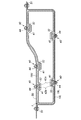
- FIG. 11 is a cross-sectional view schematically showing the vehicle body mounting structure of the fuel tank 1 according to the second embodiment of the present invention.
- the fuel tank 1 is surrounded by the band upper 10U and the band lower 10L as so-called shape restrainers, so that the deformation of the fuel tank 1 is prevented.
- the vehicle tank mounting structure of the fuel tank 1 according to the second embodiment is not provided with an independent band upper 10U, and the greatest feature is that the band upper 10U is replaced with a structure on the vehicle body side. .
- the fuel tank 1 has a three-layer structure (not shown) as in the first embodiment, and the upper wall 19U and the lower wall 19L are provided with a plurality of recesses 32 whose side surfaces are tapered. ing. And the to-be-joined member 41 which comprises the coupling means 40 is being fixed to the bottom face of the recessed part 32 by welding. An insert bolt 42b is embedded in the base 42a of the coupled member 41 by insert molding.
- the member to be coupled 41 is coupled to the band lower 10L by the insert bolt 42b and the nut 44.
- the band lower 10L is fixed to the vehicle body structure 50 by the flange part 51 provided in the edge part.
- the vehicle body structure 50 is connected to, for example, the rear side frame 2 described with reference to FIG. 1, the first cross member 3, the second cross member 4, the third cross member 5, or these members. It is a holding member such as a floor panel, a stiffener, a flange, etc., and indicates a structure having rigidity higher than at least the upper wall 19U of the fuel tank 1. Finally, the fuel tank 1 is held by the holding member.
- the member to be coupled 41 is directly coupled to the vehicle body structure 50 by the insert bolt 42b and the nut 44. Accordingly, no band upper is disposed on the side of the upper wall 19U, and there is no flange portion for attaching the band upper to the vehicle body. By doing in this way, since it does not have a band upper compared with 1st Embodiment, it is possible to attach the fuel tank 1 to a vehicle body more compactly, producing the same effect as 1st Embodiment. Become.
- the upper wall 19U is coupled to the band upper 10U
- the lower wall 19L is coupled to the band lower 10L.
- the upper wall 19U and the lower wall 19L together form a side surface.
- the present invention can also be applied to a simple fuel tank (that is, a fuel tank arranged such that the longitudinal direction is the height direction).
- the use of the fuel tank body mounting structure according to the present invention is not limited to a passenger car. It should be noted that all of the constituent elements shown in the above embodiments are not necessarily essential, and can be appropriately selected as long as they do not depart from the scope of the present invention.
- the fuel tank body mounting structure according to the present invention has a simple configuration and prevents deformation of the fuel tank even when the internal pressure of the fuel tank changes to either positive pressure or negative pressure, and is built in the fuel tank. Therefore, it can be suitably used in a passenger car equipped with a fuel tank.
Landscapes
- Engineering & Computer Science (AREA)
- Life Sciences & Earth Sciences (AREA)
- Sustainable Development (AREA)
- Sustainable Energy (AREA)
- Chemical & Material Sciences (AREA)
- Combustion & Propulsion (AREA)
- Transportation (AREA)
- Mechanical Engineering (AREA)
- Cooling, Air Intake And Gas Exhaust, And Fuel Tank Arrangements In Propulsion Units (AREA)
Abstract
Le problème posé par la présente invention consiste à fournir une structure de montage d'un réservoir de carburant sur une carrosserie de véhicule, la structure étant conçue de sorte que, indépendamment des changements de pression dans le réservoir de carburant en positif ou en négatif, la structure est capable d'éviter la déformation nuisible du réservoir de carburant, ce qui gène la fonction du réservoir de carburant.
La solution de l'invention porte sur une structure de montage d'un réservoir de carburant sur une carrosserie de véhicule, conçue de manière à comprendre : une partie (10L) inférieure de bande, fixée sur la carrosserie du véhicule, s'étendant le long, au moins, de la paroi inférieure (19L) du réservoir de carburant (1) et supporte le réservoir de carburant (1) ; un moyen de jonction (40) de paroi inférieure qui relie au moins une portion de la paroi inférieure (19L) du réservoir de carburant (1) à la partie (10L) inférieure de bande ; un élément (50) de support fixé côté carrosserie du véhicule et supportant le réservoir de carburant (1) ; et un moyen de jonction (40) de paroi supérieure qui relie au moins une portion de la paroi supérieure (19U) du réservoir de carburant (1) à l'élément de support.
Priority Applications (2)
| Application Number | Priority Date | Filing Date | Title |
|---|---|---|---|
| CN201380071858.0A CN104955670B (zh) | 2013-01-31 | 2013-09-24 | 燃料箱的车身安装结构以及燃料箱的防变形件 |
| US14/764,249 US9579972B2 (en) | 2013-01-31 | 2013-09-24 | Structure for mounting fuel tank on vehicle body and device for preventing deformation of fuel tank |
Applications Claiming Priority (2)
| Application Number | Priority Date | Filing Date | Title |
|---|---|---|---|
| JP2013017400A JP2014148227A (ja) | 2013-01-31 | 2013-01-31 | 燃料タンクの車体取付構造 |
| JP2013-017400 | 2013-01-31 |
Publications (1)
| Publication Number | Publication Date |
|---|---|
| WO2014118830A1 true WO2014118830A1 (fr) | 2014-08-07 |
Family
ID=51261581
Family Applications (1)
| Application Number | Title | Priority Date | Filing Date |
|---|---|---|---|
| PCT/JP2013/005635 Ceased WO2014118830A1 (fr) | 2013-01-31 | 2013-09-24 | Structure de montage d'un réservoir de carburant sur la carrosserie du véhicule et dispositif destiné à éviter la déformation du réservoir de carburant |
Country Status (4)
| Country | Link |
|---|---|
| US (1) | US9579972B2 (fr) |
| JP (1) | JP2014148227A (fr) |
| CN (1) | CN104955670B (fr) |
| WO (1) | WO2014118830A1 (fr) |
Cited By (2)
| Publication number | Priority date | Publication date | Assignee | Title |
|---|---|---|---|---|
| JP2016060285A (ja) * | 2014-09-16 | 2016-04-25 | 本田技研工業株式会社 | 燃料供給装置 |
| US10190554B2 (en) | 2014-04-07 | 2019-01-29 | Honda Motor Co., Ltd. | Fuel supply device |
Families Citing this family (25)
| Publication number | Priority date | Publication date | Assignee | Title |
|---|---|---|---|---|
| JP6020486B2 (ja) * | 2014-02-21 | 2016-11-02 | トヨタ自動車株式会社 | 樹脂燃料タンク |
| WO2016174936A1 (fr) * | 2015-04-27 | 2016-11-03 | 八千代工業株式会社 | Réservoir de carburant |
| JP2017019470A (ja) * | 2015-07-15 | 2017-01-26 | キャタピラー エス エー アール エル | 合成樹脂製タンク |
| KR102433215B1 (ko) * | 2015-09-25 | 2022-08-18 | (주) 엔피홀딩스 | 전기 도금 장치 및 방법 |
| JP6598062B2 (ja) * | 2015-09-28 | 2019-10-30 | スズキ株式会社 | 燃料タンクの構造 |
| JP6658562B2 (ja) | 2017-01-16 | 2020-03-04 | トヨタ自動車株式会社 | 樹脂製燃料タンク及びこれを成形するブロー成形型 |
| US10077011B1 (en) * | 2017-05-09 | 2018-09-18 | Ford Global Technologies, Llc | Vehicle underbody acoustic panels |
| JP6462055B2 (ja) * | 2017-06-30 | 2019-01-30 | 本田技研工業株式会社 | 車体構造 |
| DE102017217662A1 (de) * | 2017-10-05 | 2019-04-11 | Bayerische Motoren Werke Aktiengesellschaft | Tankanordnung an einem Rahmen eines Kraftrads, Rahmenelement für ein Kraftrad sowie Montageverfahren |
| JP2019105204A (ja) * | 2017-12-12 | 2019-06-27 | スズキ株式会社 | 車両下部構造 |
| JP7003632B2 (ja) * | 2017-12-20 | 2022-01-20 | スズキ株式会社 | 燃料タンクの固定構造 |
| FR3077780B1 (fr) | 2018-02-13 | 2020-01-17 | Psa Automobiles Sa | Ensemble d’un support raidisseur et d’une sangle pour reservoir de carburant de vehicule automobile |
| DE102018105009A1 (de) * | 2018-03-05 | 2019-09-05 | Jungheinrich Aktiengesellschaft | Flurförderzeug mit einem Hydraulikflüssigkeitstank |
| US20190283573A1 (en) * | 2018-03-16 | 2019-09-19 | Kwang Yang Motor Co., Ltd. | Tank holding device and a vehicle having the same |
| JP7119492B2 (ja) * | 2018-03-28 | 2022-08-17 | マツダ株式会社 | 燃料タンク保護構造 |
| US20200016976A1 (en) * | 2018-07-10 | 2020-01-16 | Honda Motor Co., Ltd | High pressure resin fuel tank with internal bracket support structure, flexible union structure, and external steel pipe reinforcement |
| CN110722980A (zh) * | 2018-07-17 | 2020-01-24 | 泽菲罗斯有限公司 | 用于燃料箱的结构增强件 |
| WO2020071312A1 (fr) * | 2018-10-04 | 2020-04-09 | 八千代工業株式会社 | Réservoir de carburant |
| JP2019006398A (ja) * | 2018-10-05 | 2019-01-17 | 株式会社クボタ | 作業車 |
| US11491867B2 (en) * | 2019-05-14 | 2022-11-08 | Ford Global Technologies, Llc | Fuel tank assembly and method for manufacture of the fuel tank assembly |
| FR3098764A1 (fr) * | 2019-07-19 | 2021-01-22 | Plastic Omnium Advanced Innovation And Research | Dispositif de fixation pour un composant à un réservoir à carburant |
| JP7481221B2 (ja) * | 2020-09-30 | 2024-05-10 | 株式会社Subaru | 燃料電池車両 |
| WO2023008206A1 (fr) * | 2021-07-26 | 2023-02-02 | 八千代工業株式会社 | Réservoir de carburant |
| DE102022134403A1 (de) * | 2022-12-21 | 2024-06-27 | Bayerische Motoren Werke Aktiengesellschaft | Haltebandanordnung, Verfahren zum Befestigen einer Komponente und Kraftfahrzeug |
| CN119953298A (zh) * | 2025-03-05 | 2025-05-09 | 一汽解放汽车有限公司 | 车辆外部附属安全装置及车辆 |
Citations (4)
| Publication number | Priority date | Publication date | Assignee | Title |
|---|---|---|---|---|
| JPH0169029U (fr) * | 1987-10-28 | 1989-05-08 | ||
| JPH0173025U (fr) * | 1987-10-30 | 1989-05-17 | ||
| JPH10114227A (ja) * | 1996-10-09 | 1998-05-06 | Mitsubishi Motors Corp | 燃料タンクの車両搭載構造 |
| JP2010221889A (ja) * | 2009-03-24 | 2010-10-07 | Honda Motor Co Ltd | 車両用燃料タンクおよび車両用燃料タンクの製造方法 |
Family Cites Families (17)
| Publication number | Priority date | Publication date | Assignee | Title |
|---|---|---|---|---|
| FR2082428A5 (fr) * | 1970-03-13 | 1971-12-10 | Citroen Sa | |
| US4371181A (en) * | 1980-04-29 | 1983-02-01 | Monigold Ray A | Collision resistant auxiliary fuel system |
| JPH0737388B2 (ja) | 1987-02-10 | 1995-04-26 | 田辺製薬株式会社 | 腎機能改善剤 |
| JPH05294150A (ja) | 1992-04-21 | 1993-11-09 | Horie Kinzoku Kogyo Kk | 燃料タンクの支持構造 |
| JP3461387B2 (ja) * | 1994-07-26 | 2003-10-27 | 本田技研工業株式会社 | 燃料タンクの固定構造 |
| US5574539A (en) | 1995-09-18 | 1996-11-12 | Xerox Corporation | Toner maintenance subsystem for a printing machine |
| US6099042A (en) * | 1997-12-05 | 2000-08-08 | Ford Global Technologies, Inc. | Fuel tank support |
| JP4075744B2 (ja) * | 2003-02-12 | 2008-04-16 | 日産自動車株式会社 | 燃料タンクの取付構造 |
| KR100530137B1 (ko) * | 2004-05-24 | 2005-11-21 | 기아자동차주식회사 | 자동차의 연료탱크 충돌방지 장치 |
| JP2006001381A (ja) | 2004-06-16 | 2006-01-05 | Honda Motor Co Ltd | 固定部材 |
| JP4581621B2 (ja) * | 2004-10-19 | 2010-11-17 | マツダ株式会社 | 車両の燃料タンク支持構造 |
| WO2007133213A1 (fr) * | 2006-05-17 | 2007-11-22 | Mack Trucks, Inc. | Agencement de montage de réservoir à carburant et procédé de montage d'un réservoir à carburant |
| JP2011093409A (ja) | 2009-10-29 | 2011-05-12 | Yachiyo Industry Co Ltd | 燃料タンクの付属部品の取付構造 |
| DE102011009636A1 (de) * | 2011-01-27 | 2012-08-02 | GM Global Technology Operations LLC (n. d. Ges. d. Staates Delaware) | Anordnung zur Befestigung eines Kraftstoffbehälters an einer Fahrzeugkarosserie |
| US9145052B2 (en) * | 2012-10-17 | 2015-09-29 | Dbg | Vehicle fuel tank mounting assembly and installation method |
| US8960360B2 (en) * | 2013-01-15 | 2015-02-24 | GM Global Technology Operations LLC | Integrated vehicle structure and power-plant exhaust |
| US9376013B2 (en) * | 2014-08-05 | 2016-06-28 | KIRCHHOFF Van-Rob Automotive | Composite fuel tank support |
-
2013
- 2013-01-31 JP JP2013017400A patent/JP2014148227A/ja active Pending
- 2013-09-24 US US14/764,249 patent/US9579972B2/en active Active
- 2013-09-24 WO PCT/JP2013/005635 patent/WO2014118830A1/fr not_active Ceased
- 2013-09-24 CN CN201380071858.0A patent/CN104955670B/zh active Active
Patent Citations (4)
| Publication number | Priority date | Publication date | Assignee | Title |
|---|---|---|---|---|
| JPH0169029U (fr) * | 1987-10-28 | 1989-05-08 | ||
| JPH0173025U (fr) * | 1987-10-30 | 1989-05-17 | ||
| JPH10114227A (ja) * | 1996-10-09 | 1998-05-06 | Mitsubishi Motors Corp | 燃料タンクの車両搭載構造 |
| JP2010221889A (ja) * | 2009-03-24 | 2010-10-07 | Honda Motor Co Ltd | 車両用燃料タンクおよび車両用燃料タンクの製造方法 |
Cited By (2)
| Publication number | Priority date | Publication date | Assignee | Title |
|---|---|---|---|---|
| US10190554B2 (en) | 2014-04-07 | 2019-01-29 | Honda Motor Co., Ltd. | Fuel supply device |
| JP2016060285A (ja) * | 2014-09-16 | 2016-04-25 | 本田技研工業株式会社 | 燃料供給装置 |
Also Published As
| Publication number | Publication date |
|---|---|
| US9579972B2 (en) | 2017-02-28 |
| CN104955670B (zh) | 2017-05-10 |
| US20150367726A1 (en) | 2015-12-24 |
| CN104955670A (zh) | 2015-09-30 |
| JP2014148227A (ja) | 2014-08-21 |
Similar Documents
| Publication | Publication Date | Title |
|---|---|---|
| WO2014118830A1 (fr) | Structure de montage d'un réservoir de carburant sur la carrosserie du véhicule et dispositif destiné à éviter la déformation du réservoir de carburant | |
| US9010840B2 (en) | Exterior module with an exterior panelling for a modularly constructed housing component and the modularly constructed housing component itself, and method for producing the exterior module | |
| JP2006192919A (ja) | 自動車用燃料タンクおよびその製造方法 | |
| JP5877577B2 (ja) | 自動車用燃料タンク | |
| JP2017030583A (ja) | 自動車用バンパービーム、バンパービームの製造方法およびバンパービームの車体取付構造 | |
| JP6206555B2 (ja) | 樹脂製サンドイッチパネルおよび樹脂製サンドイッチパネルの製造方法 | |
| JP5971073B2 (ja) | 樹脂製サンドイッチパネルおよび樹脂製サンドイッチパネルの製造方法 | |
| CN105579271B (zh) | 机动车用燃料箱的制造方法 | |
| JP5973341B2 (ja) | 車両用アンダーカバーの製造方法 | |
| CN105291821B (zh) | 汽车用燃料箱的制造方法 | |
| US12258071B2 (en) | Method for manufacturing lightweight cowl crossbar | |
| JP2009132296A (ja) | 自動車用燃料タンク | |
| JP2015058715A (ja) | 自動車用燃料タンク | |
| JP5350086B2 (ja) | 樹脂製燃料タンク | |
| JP2006143057A (ja) | 自動車用燃料タンクおよびその製造方法 | |
| WO2014058059A1 (fr) | Panneau pris en sandwich dans de la résine et son procédé de fabrication | |
| CN108312843B (zh) | 树脂燃料箱和用于使树脂燃料箱成型的吹塑成型模具 | |
| JP2005205800A (ja) | 車両内装用溶着部材 | |
| JP6533418B2 (ja) | 燃料タンク | |
| JP2015000644A (ja) | フィラーパイプとその製造方法 | |
| JP7035906B2 (ja) | ルーフリインフォースメント及び樹脂中空骨格部材の製造方法 | |
| JP5880926B2 (ja) | 車両用内装材の製造方法 | |
| US20210023811A1 (en) | Sandwich-Type, Composite Component Having an Injection Molded Backside Protective Covering | |
| JP5060194B2 (ja) | 燃料タンク | |
| JP2015085516A (ja) | ブロー成形体 |
Legal Events
| Date | Code | Title | Description |
|---|---|---|---|
| 121 | Ep: the epo has been informed by wipo that ep was designated in this application |
Ref document number: 13873296 Country of ref document: EP Kind code of ref document: A1 |
|
| WWE | Wipo information: entry into national phase |
Ref document number: 14764249 Country of ref document: US |
|
| NENP | Non-entry into the national phase |
Ref country code: DE |
|
| 122 | Ep: pct application non-entry in european phase |
Ref document number: 13873296 Country of ref document: EP Kind code of ref document: A1 |