WO2014147788A1 - Échangeur de chaleur, dispositif à cycle de réfrigération, et méthode de production pour échangeur de chaleur - Google Patents
Échangeur de chaleur, dispositif à cycle de réfrigération, et méthode de production pour échangeur de chaleur Download PDFInfo
- Publication number
- WO2014147788A1 WO2014147788A1 PCT/JP2013/058060 JP2013058060W WO2014147788A1 WO 2014147788 A1 WO2014147788 A1 WO 2014147788A1 JP 2013058060 W JP2013058060 W JP 2013058060W WO 2014147788 A1 WO2014147788 A1 WO 2014147788A1
- Authority
- WO
- WIPO (PCT)
- Prior art keywords
- heat transfer
- heat exchanger
- fins
- transfer tubes
- heat
- Prior art date
- Legal status (The legal status is an assumption and is not a legal conclusion. Google has not performed a legal analysis and makes no representation as to the accuracy of the status listed.)
- Ceased
Links
Images


Classifications
-
- F—MECHANICAL ENGINEERING; LIGHTING; HEATING; WEAPONS; BLASTING
- F28—HEAT EXCHANGE IN GENERAL
- F28D—HEAT-EXCHANGE APPARATUS, NOT PROVIDED FOR IN ANOTHER SUBCLASS, IN WHICH THE HEAT-EXCHANGE MEDIA DO NOT COME INTO DIRECT CONTACT
- F28D1/00—Heat-exchange apparatus having stationary conduit assemblies for one heat-exchange medium only, the media being in contact with different sides of the conduit wall, in which the other heat-exchange medium is a large body of fluid, e.g. domestic or motor car radiators
- F28D1/02—Heat-exchange apparatus having stationary conduit assemblies for one heat-exchange medium only, the media being in contact with different sides of the conduit wall, in which the other heat-exchange medium is a large body of fluid, e.g. domestic or motor car radiators with heat-exchange conduits immersed in the body of fluid
- F28D1/0233—Heat-exchange apparatus having stationary conduit assemblies for one heat-exchange medium only, the media being in contact with different sides of the conduit wall, in which the other heat-exchange medium is a large body of fluid, e.g. domestic or motor car radiators with heat-exchange conduits immersed in the body of fluid with air flow channels
-
- B—PERFORMING OPERATIONS; TRANSPORTING
- B23—MACHINE TOOLS; METAL-WORKING NOT OTHERWISE PROVIDED FOR
- B23P—METAL-WORKING NOT OTHERWISE PROVIDED FOR; COMBINED OPERATIONS; UNIVERSAL MACHINE TOOLS
- B23P15/00—Making specific metal objects by operations not covered by a single other subclass or a group in this subclass
- B23P15/26—Making specific metal objects by operations not covered by a single other subclass or a group in this subclass heat exchangers or the like
-
- F—MECHANICAL ENGINEERING; LIGHTING; HEATING; WEAPONS; BLASTING
- F02—COMBUSTION ENGINES; HOT-GAS OR COMBUSTION-PRODUCT ENGINE PLANTS
- F02G—HOT GAS OR COMBUSTION-PRODUCT POSITIVE-DISPLACEMENT ENGINE PLANTS; USE OF WASTE HEAT OF COMBUSTION ENGINES; NOT OTHERWISE PROVIDED FOR
- F02G1/00—Hot gas positive-displacement engine plants
- F02G1/04—Hot gas positive-displacement engine plants of closed-cycle type
- F02G1/043—Hot gas positive-displacement engine plants of closed-cycle type the engine being operated by expansion and contraction of a mass of working gas which is heated and cooled in one of a plurality of constantly communicating expansible chambers, e.g. Stirling cycle type engines
- F02G1/053—Component parts or details
-
- F—MECHANICAL ENGINEERING; LIGHTING; HEATING; WEAPONS; BLASTING
- F28—HEAT EXCHANGE IN GENERAL
- F28D—HEAT-EXCHANGE APPARATUS, NOT PROVIDED FOR IN ANOTHER SUBCLASS, IN WHICH THE HEAT-EXCHANGE MEDIA DO NOT COME INTO DIRECT CONTACT
- F28D1/00—Heat-exchange apparatus having stationary conduit assemblies for one heat-exchange medium only, the media being in contact with different sides of the conduit wall, in which the other heat-exchange medium is a large body of fluid, e.g. domestic or motor car radiators
- F28D1/02—Heat-exchange apparatus having stationary conduit assemblies for one heat-exchange medium only, the media being in contact with different sides of the conduit wall, in which the other heat-exchange medium is a large body of fluid, e.g. domestic or motor car radiators with heat-exchange conduits immersed in the body of fluid
- F28D1/04—Heat-exchange apparatus having stationary conduit assemblies for one heat-exchange medium only, the media being in contact with different sides of the conduit wall, in which the other heat-exchange medium is a large body of fluid, e.g. domestic or motor car radiators with heat-exchange conduits immersed in the body of fluid with tubular conduits
- F28D1/047—Heat-exchange apparatus having stationary conduit assemblies for one heat-exchange medium only, the media being in contact with different sides of the conduit wall, in which the other heat-exchange medium is a large body of fluid, e.g. domestic or motor car radiators with heat-exchange conduits immersed in the body of fluid with tubular conduits the conduits being bent, e.g. in a serpentine or zig-zag
-
- F—MECHANICAL ENGINEERING; LIGHTING; HEATING; WEAPONS; BLASTING
- F28—HEAT EXCHANGE IN GENERAL
- F28D—HEAT-EXCHANGE APPARATUS, NOT PROVIDED FOR IN ANOTHER SUBCLASS, IN WHICH THE HEAT-EXCHANGE MEDIA DO NOT COME INTO DIRECT CONTACT
- F28D1/00—Heat-exchange apparatus having stationary conduit assemblies for one heat-exchange medium only, the media being in contact with different sides of the conduit wall, in which the other heat-exchange medium is a large body of fluid, e.g. domestic or motor car radiators
- F28D1/02—Heat-exchange apparatus having stationary conduit assemblies for one heat-exchange medium only, the media being in contact with different sides of the conduit wall, in which the other heat-exchange medium is a large body of fluid, e.g. domestic or motor car radiators with heat-exchange conduits immersed in the body of fluid
- F28D1/04—Heat-exchange apparatus having stationary conduit assemblies for one heat-exchange medium only, the media being in contact with different sides of the conduit wall, in which the other heat-exchange medium is a large body of fluid, e.g. domestic or motor car radiators with heat-exchange conduits immersed in the body of fluid with tubular conduits
- F28D1/053—Heat-exchange apparatus having stationary conduit assemblies for one heat-exchange medium only, the media being in contact with different sides of the conduit wall, in which the other heat-exchange medium is a large body of fluid, e.g. domestic or motor car radiators with heat-exchange conduits immersed in the body of fluid with tubular conduits the conduits being straight
-
- F—MECHANICAL ENGINEERING; LIGHTING; HEATING; WEAPONS; BLASTING
- F28—HEAT EXCHANGE IN GENERAL
- F28F—DETAILS OF HEAT-EXCHANGE AND HEAT-TRANSFER APPARATUS, OF GENERAL APPLICATION
- F28F1/00—Tubular elements; Assemblies of tubular elements
- F28F1/10—Tubular elements and assemblies thereof with means for increasing heat-transfer area, e.g. with fins, with projections, with recesses
- F28F1/12—Tubular elements and assemblies thereof with means for increasing heat-transfer area, e.g. with fins, with projections, with recesses the means being only outside the tubular element
- F28F1/24—Tubular elements and assemblies thereof with means for increasing heat-transfer area, e.g. with fins, with projections, with recesses the means being only outside the tubular element and extending transversely
- F28F1/30—Tubular elements and assemblies thereof with means for increasing heat-transfer area, e.g. with fins, with projections, with recesses the means being only outside the tubular element and extending transversely the means being attachable to the element
-
- F—MECHANICAL ENGINEERING; LIGHTING; HEATING; WEAPONS; BLASTING
- F28—HEAT EXCHANGE IN GENERAL
- F28F—DETAILS OF HEAT-EXCHANGE AND HEAT-TRANSFER APPARATUS, OF GENERAL APPLICATION
- F28F1/00—Tubular elements; Assemblies of tubular elements
- F28F1/10—Tubular elements and assemblies thereof with means for increasing heat-transfer area, e.g. with fins, with projections, with recesses
- F28F1/12—Tubular elements and assemblies thereof with means for increasing heat-transfer area, e.g. with fins, with projections, with recesses the means being only outside the tubular element
- F28F1/24—Tubular elements and assemblies thereof with means for increasing heat-transfer area, e.g. with fins, with projections, with recesses the means being only outside the tubular element and extending transversely
- F28F1/32—Tubular elements and assemblies thereof with means for increasing heat-transfer area, e.g. with fins, with projections, with recesses the means being only outside the tubular element and extending transversely the means having portions engaging further tubular elements
-
- F—MECHANICAL ENGINEERING; LIGHTING; HEATING; WEAPONS; BLASTING
- F28—HEAT EXCHANGE IN GENERAL
- F28F—DETAILS OF HEAT-EXCHANGE AND HEAT-TRANSFER APPARATUS, OF GENERAL APPLICATION
- F28F1/00—Tubular elements; Assemblies of tubular elements
- F28F1/10—Tubular elements and assemblies thereof with means for increasing heat-transfer area, e.g. with fins, with projections, with recesses
- F28F1/12—Tubular elements and assemblies thereof with means for increasing heat-transfer area, e.g. with fins, with projections, with recesses the means being only outside the tubular element
- F28F1/38—Tubular elements and assemblies thereof with means for increasing heat-transfer area, e.g. with fins, with projections, with recesses the means being only outside the tubular element and being staggered to form tortuous fluid passages
-
- F—MECHANICAL ENGINEERING; LIGHTING; HEATING; WEAPONS; BLASTING
- F28—HEAT EXCHANGE IN GENERAL
- F28F—DETAILS OF HEAT-EXCHANGE AND HEAT-TRANSFER APPARATUS, OF GENERAL APPLICATION
- F28F1/00—Tubular elements; Assemblies of tubular elements
- F28F1/10—Tubular elements and assemblies thereof with means for increasing heat-transfer area, e.g. with fins, with projections, with recesses
- F28F1/40—Tubular elements and assemblies thereof with means for increasing heat-transfer area, e.g. with fins, with projections, with recesses the means being only inside the tubular element
-
- F—MECHANICAL ENGINEERING; LIGHTING; HEATING; WEAPONS; BLASTING
- F28—HEAT EXCHANGE IN GENERAL
- F28F—DETAILS OF HEAT-EXCHANGE AND HEAT-TRANSFER APPARATUS, OF GENERAL APPLICATION
- F28F1/00—Tubular elements; Assemblies of tubular elements
- F28F1/10—Tubular elements and assemblies thereof with means for increasing heat-transfer area, e.g. with fins, with projections, with recesses
- F28F1/42—Tubular elements and assemblies thereof with means for increasing heat-transfer area, e.g. with fins, with projections, with recesses the means being both outside and inside the tubular element
-
- F—MECHANICAL ENGINEERING; LIGHTING; HEATING; WEAPONS; BLASTING
- F28—HEAT EXCHANGE IN GENERAL
- F28F—DETAILS OF HEAT-EXCHANGE AND HEAT-TRANSFER APPARATUS, OF GENERAL APPLICATION
- F28F21/00—Constructions of heat-exchange apparatus characterised by the selection of particular materials
- F28F21/08—Constructions of heat-exchange apparatus characterised by the selection of particular materials of metal
- F28F21/081—Heat exchange elements made from metals or metal alloys
- F28F21/085—Heat exchange elements made from metals or metal alloys from copper or copper alloys
-
- F—MECHANICAL ENGINEERING; LIGHTING; HEATING; WEAPONS; BLASTING
- F28—HEAT EXCHANGE IN GENERAL
- F28D—HEAT-EXCHANGE APPARATUS, NOT PROVIDED FOR IN ANOTHER SUBCLASS, IN WHICH THE HEAT-EXCHANGE MEDIA DO NOT COME INTO DIRECT CONTACT
- F28D21/00—Heat-exchange apparatus not covered by any of the groups F28D1/00 - F28D20/00
- F28D2021/0019—Other heat exchangers for particular applications; Heat exchange systems not otherwise provided for
- F28D2021/0068—Other heat exchangers for particular applications; Heat exchange systems not otherwise provided for for refrigerant cycles
- F28D2021/007—Condensers
-
- F—MECHANICAL ENGINEERING; LIGHTING; HEATING; WEAPONS; BLASTING
- F28—HEAT EXCHANGE IN GENERAL
- F28D—HEAT-EXCHANGE APPARATUS, NOT PROVIDED FOR IN ANOTHER SUBCLASS, IN WHICH THE HEAT-EXCHANGE MEDIA DO NOT COME INTO DIRECT CONTACT
- F28D21/00—Heat-exchange apparatus not covered by any of the groups F28D1/00 - F28D20/00
- F28D2021/0019—Other heat exchangers for particular applications; Heat exchange systems not otherwise provided for
- F28D2021/0068—Other heat exchangers for particular applications; Heat exchange systems not otherwise provided for for refrigerant cycles
- F28D2021/0071—Evaporators
-
- F—MECHANICAL ENGINEERING; LIGHTING; HEATING; WEAPONS; BLASTING
- F28—HEAT EXCHANGE IN GENERAL
- F28F—DETAILS OF HEAT-EXCHANGE AND HEAT-TRANSFER APPARATUS, OF GENERAL APPLICATION
- F28F2275/00—Fastening; Joining
- F28F2275/12—Fastening; Joining by methods involving deformation of the elements
- F28F2275/125—Fastening; Joining by methods involving deformation of the elements by bringing elements together and expanding
Definitions
- the present invention relates to a heat exchanger provided with a heat transfer tube, a refrigeration cycle apparatus using the heat exchanger, and a method for manufacturing the heat exchanger.
- a heat exchanger having a plurality of fins arranged at intervals and through which a gas (for example, air) flows and a heat transfer tube that is inserted into the plurality of fins and into which a medium (for example, a refrigerant) flows is known. It has been.
- a technique for improving heat transfer performance by optimizing the row pitch and step pitch of the heat transfer tubes and slitting the fins has been proposed (see, for example, Patent Document 1).
- copper-based metal materials such as copper or copper alloys have been used as materials for fins and heat transfer tubes of heat exchangers.
- the copper-based metal material has low deformation resistance, if the pipe is expanded to fix the heat transfer tube to the fin, the adhesion between the outer surface of the heat transfer tube and the fin is lowered, and the heat transfer rate is lowered. For this reason, the heat transfer performance of the heat exchanger is lowered, and there is a problem that the heat exchange capacity is lowered.
- the present invention has been made to solve the above-described problems, and an object of the present invention is to obtain a heat exchanger, a refrigeration cycle apparatus, and a method of manufacturing a heat exchanger that can suppress a decrease in heat exchange capacity.
- the heat exchanger according to the present invention is arranged at intervals, a plurality of fins through which gas flows, a plurality of heat transfer tubes inserted into the plurality of fins and joined to the plurality of fins by pipe expansion,
- the plurality of fins and the plurality of heat transfer tubes are made of a copper-based metal material, and the plurality of heat transfer tubes are adjacent to each other with the outer diameter before expanding the tube D and the outer diameter after expanding the tube Da.
- the present invention can suppress a decrease in adhesion between the outer surface of the heat transfer tube and the fin. Moreover, the fall of the heat exchange capability of a heat exchanger can be suppressed.
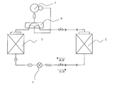
- FIG. 1 is a diagram showing a configuration of an air conditioner according to Embodiment 1 of the present invention.
- an air conditioner will be described as an example of the refrigeration cycle apparatus of the present invention.
- the air conditioner includes a compressor 5, a four-way valve 8, an outdoor heat exchanger 3, an expansion valve 7, and an indoor heat exchanger 2 that are sequentially connected by refrigerant piping to circulate the refrigerant.
- a refrigerant circuit is provided.
- the expansion valve 7 corresponds to “expansion means” in the present invention.
- the four-way valve 8 switches between the heating operation and the cooling operation by switching the flow direction of the refrigerant in the refrigerant circuit.
- the four-way valve 8 may be omitted.
- the indoor side heat exchanger 2 is mounted on an indoor unit.
- the indoor heat exchanger 2 functions as a refrigerant evaporator during the cooling operation.
- the indoor heat exchanger 2 functions as a refrigerant condenser during heating operation.
- the outdoor heat exchanger 3 is mounted on an outdoor unit.
- the outdoor heat exchanger 3 functions as a condenser that heats air or the like with the heat of the refrigerant during cooling operation.
- the outdoor heat exchanger 3 functions as an evaporator that evaporates the refrigerant and cools air or the like with the heat of vaporization at the time of heating operation.
- the compressor 5 compresses the refrigerant discharged from the evaporator and supplies it to the condenser at a high temperature.
- the expansion valve 7 expands the refrigerant discharged from the condenser, and supplies it to the evaporator at a low temperature.
- an HC single refrigerant a mixed refrigerant containing HC, a mixed refrigerant containing at least one of R32, R410A, R407C, carbon dioxide, R1234yf, and R1234yf, a mixed refrigerant containing at least one of R1234ze and R1234ze, Either of these is used.
- These refrigerants are refrigerants having a small pressure loss in the heat transfer tube 20. For this reason, by using any of these refrigerants, the heat transfer performance in the tube can be improved without increasing the pressure loss in the tube of the heat transfer tube 20. Therefore, the highly efficient heat exchanger 1 can be provided. In particular, if the diameter of the heat transfer tube 20 is reduced, it is necessary to increase the thickness of the bottom of a groove 21 (described later) of the heat transfer tube 20, and this effect is remarkable.
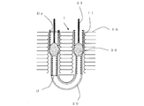
- FIG. 2 is a diagram showing a state of pipe expansion by the machine pipe expansion method.
- the mechanical tube expansion system is a method in which a rod 31 having a tube ball 30 with a diameter slightly larger than the inner diameter of the heat transfer tube 20 is passed through the tube of the heat transfer tube 20 and the outer diameter of the heat transfer tube 20 is expanded. This is a bonding method in which 20 and the fin 10 are closely attached.
- the outer diameter of the heat transfer tube 20 before the expansion is D.
- the outer diameter after tube expansion is defined as Da.
- the heat transfer tube 20 is bent into a hairpin shape at a predetermined bending pitch at the central portion in the longitudinal direction. Through holes are formed in the fins 10 and are arranged with a space therebetween. A fin collar 11 is formed in the through hole of the fin 10.
- the heat transfer tubes 20 are inserted into the through holes of the plurality of fins 10 arranged at intervals. Then, the heat transfer tube 20 is expanded by a mechanical tube expansion method, the outer surface of the heat transfer tube 20 and the fin collar 11 of the fin 10 are brought into close contact, and the heat transfer tube 20 and the fin 10 are joined. In the example shown in FIG. 2, the heat transfer tube 20 is bent into a hairpin shape, but the present invention is not limited to this.
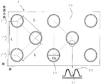
- FIG. 3 is a diagram showing a heat exchanger according to Embodiment 1 of the present invention.
- FIG. 3 shows a part of a cross section of the heat exchanger 1 as viewed from the side.
- the partial enlarged view in FIG. 3 has shown the groove
- the heat exchanger 1 includes a plurality of fins 10 and a plurality of heat transfer tubes 20.
- the plurality of fins 10 are arranged at intervals, and gas (for example, air) flows therebetween.
- a medium for example, a refrigerant
- the plurality of heat transfer tubes 20 are arranged in a plurality of stages in a step direction intersecting the gas flow direction (air flow direction).
- the plurality of heat transfer tubes 20 are arranged in a plurality of rows in the row direction along the gas flow direction (air flow direction).
- the heat transfer tube 20 becomes a part of the refrigerant circuit in the refrigeration cycle apparatus.
- the heat exchanger 1 exchanges heat between the refrigerant flowing inside the heat transfer tube 20 and the air passing between the plurality of fins 10.
- the heat exchanger 1 transfers the heat (hot or cold) inside the heat transfer tube 20 to the air via the fins 10, so that the heat transfer area serving as a contact surface with the air is expanded. For this reason, heat exchange between a refrigerant and air can be performed efficiently.
- the plurality of fins 10 and the plurality of heat transfer tubes 20 are made of a copper-based metal material such as copper or a copper alloy.
- the plurality of fins 10 are made of oxygen-free copper (JIS standard: C1020).
- the plurality of heat transfer tubes 20 are made of oxygen-free copper having higher deformation resistance than the plurality of fins 10. Copper-based metal materials have high conductivity. Also, copper-based metal materials have low deformation resistance. For this reason, when the heat transfer tube 20 is joined to the fins 10 by the mechanical expansion method, the adhesiveness between the heat transfer tubes 20 and the fins 10 can be secured, and the highly efficient heat exchanger 1 can be obtained.
- a plurality of grooves 21 extending in the axial direction are formed on the inner wall surfaces of the plurality of heat transfer tubes 20. Projections 22 are formed between the grooves 21.
- the plurality of grooves 21 may be spiral grooves having a predetermined lead angle or straight grooves.
- the plurality of heat transfer tubes 20 have an outer diameter D before expansion of, for example, 3 mm ⁇ D ⁇ 6 mm.
- the plurality of heat transfer tubes 20 satisfy the relationship of 1.055D ⁇ Da ⁇ 1.068D, where D is the outer diameter before tube expansion and Da is the outer diameter after tube expansion.
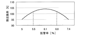
- FIG. 4 is a diagram showing the relationship between the expansion rate of the heat transfer tubes and the heat exchange rate of the heat exchanger.
- the relationship between the expansion rate of the heat transfer tube 20 and the heat exchange rate is shown with the heat exchange rate of the conventional heat exchanger as a reference (100%).
- the heat exchange rate decreases. This is because when the diameter expansion rate increases, the amount of the crest portion of the protrusion 22 crushed by the tube expansion ball 30 increases, and the heat transfer area of the inner wall surface of the heat transfer tube 20 decreases. Further, when the diameter expansion rate is increased, the fin collar 11 is cracked or deformed, and the adhesion between the heat transfer tube 20 and the fin 10 is reduced. On the other hand, if the tube expansion rate becomes too small, the heat exchange rate decreases. This is because if the diameter expansion rate is small, the outer surface of the heat transfer tube 20 does not sufficiently adhere to the fin 10, and the adhesion between the heat transfer tube 20 and the fin 10 decreases.
- the value of the pipe expansion rate so that it becomes a value (100% or more) that can improve the heat exchange rate as compared with the conventional heat exchanger.
- the heat transfer tube 20 desirably satisfies the relationship of 1.055D ⁇ Da ⁇ 1.068D.
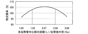
- the plurality of heat transfer tubes 20 satisfy the relationship of 1.56 Da ⁇ L ⁇ 2.58 Da, where L is the distance connecting the centers of the adjacent heat transfer tubes 20.
- the plurality of fins 10 are formed in a flat plate shape and continuously connect between the step directions of the plurality of heat transfer tubes 20. That is, there is no notch such as a slit in the step direction, and they are continuously connected. Further, the plurality of fins 10 are continuously connected between the row directions of the plurality of heat transfer tubes 20. That is, they are continuously connected in the row direction without a cut such as a heat cutoff. Note that only at least one of the column direction and the column direction may be continuously connected.
- FIG. 5 is a diagram showing the relationship between the distance L between each heat transfer tube center of the heat transfer tubes of the heat exchanger and the heat exchange rate.
- the ratio (L / Da) of the distance L from each heat transfer tube center to the outer diameter Da after the diameter expansion, with the heat exchange rate of the conventional heat exchanger as a reference (100%), and heat exchange The relationship with the rate is shown.
- the distance L is a distance connecting the centers of adjacent heat transfer tubes 20 as shown in FIG.
- L / Da becomes too large, the heat exchange rate decreases. This is because if L / Da is too large, the fins 10 between the heat transfer tubes 20 are deformed, and the adhesion between the heat transfer tubes 20 and the fins 10 is reduced.
- Embodiment 2 FIG. In the second embodiment, the relationship between the number of strips representing the total number of protrusions 22 of the heat transfer tubes 20 of the heat exchanger 1 and the heat exchange rate will be described.
- the structure of the heat exchanger 1 in this Embodiment 2 is the same as that of the said Embodiment 1, and attaches
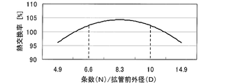
- the plurality of heat transfer tubes 20 have a plurality of axially extending grooves 21 formed on the inner wall surface and the number of protrusions 22 representing the total number of protrusions 22 formed between the grooves 21 is N, 6.66D ⁇ The relationship of N ⁇ 10D is satisfied.
- the unit of D is mm.
- FIG. 6 is a diagram showing the relationship between the number of strips representing the total number of protrusions of the heat transfer tubes of the heat exchanger and the heat exchange rate.
- FIG. 6 shows the relationship between the ratio of the number N of strips to the outer diameter D before diameter expansion (N / D) and the heat exchange rate based on the heat exchange rate of the conventional heat exchanger (100%) It is.
- N / D the heat transfer area on the inner wall surface increases as the number N of the protrusions 22 between the grooves 21 increases.
- N / D becomes too large, the heat exchange rate decreases.
- Embodiment 3 FIG. In the third embodiment, the relationship between the fin pitch in the stacking direction of the fins 10 and the heat exchange rate will be described.
- the structure of the heat exchanger 1 in this Embodiment 3 is the same as that of the said Embodiment 1, and attaches
- the plurality of fins 10 satisfy a relationship of 0.3D ⁇ Fp ⁇ 0.58D, where Fp is a fin pitch that is an interval between adjacent fins 10.
- FIG. 7 is a diagram showing the relationship between the fin pitch Fp in the stacking direction of the fins of the heat exchanger and the heat exchange rate.
- FIG. 7 shows the relationship between the ratio (Fp / D) of the fin pitch Fp to the outer diameter D before diameter expansion and the heat exchange rate, with the heat exchange rate of the conventional heat exchanger as a reference (100%). It is.
- the fin pitch Fp is increased, the airflow resistance of the air passing between the plurality of fins 10 is reduced.
- the air volume can be increased without increasing the driving force of the blower that supplies air to the heat exchanger 1, so that the heat exchange rate of the heat exchanger 1 can be improved.
- FIG. 7 shows the relationship between the fin pitch Fp in the stacking direction of the fins of the heat exchanger and the heat exchange rate.
- the value of Fp / D so as to be a value (100% or more) that can improve the heat exchange rate as compared with the conventional heat exchanger.
- the relationship of 0.3D ⁇ Fp ⁇ 0.58D is satisfied as shown in FIG.
- the heat exchange rate of the heat exchanger 1 can be improved.
- the heat exchange capability of the heat exchanger 1 can be improved. Therefore, the highly efficient heat exchanger 1 can be obtained. Therefore, the efficiency of the refrigeration cycle apparatus can be improved.
- Embodiment 4 FIG. In the fourth embodiment, the relationship between the thickness of the fin 10 and the heat exchange rate will be described.
- the structure of the heat exchanger 1 in this Embodiment 4 is the same as that of the said Embodiment 1, and attaches
- the plurality of fins 10 satisfy the relationship of 0.026D ⁇ Ft ⁇ 0.037D when the thickness in the stacking direction is Ft.
- FIG. 8 is a diagram showing the relationship between the fin thickness Ft of the heat exchanger and the heat exchange rate.
- the ventilation resistance of the air passing between the plurality of fins 10 is reduced.
- the air volume can be increased without increasing the driving force of the blower that supplies air to the heat exchanger 1, so that the heat exchange rate of the heat exchanger 1 can be improved.
- Ft / D becomes too small, the heat exchange efficiency decreases.
- the value of Ft / D so as to be a value (100% or more) that can improve the heat exchange rate as compared with the conventional heat exchanger.
- the heat exchange rate of the heat exchanger 1 can be improved.
- the heat exchange capability of the heat exchanger 1 can be improved. Therefore, the highly efficient heat exchanger 1 can be obtained. Therefore, the efficiency of the refrigeration cycle apparatus can be improved.
- Embodiments 1 to 4 may be arbitrarily combined. Even in such a configuration, the heat exchange rate of the heat exchanger 1 can be improved. Moreover, the heat exchange capability of the heat exchanger 1 can be improved. Therefore, the highly efficient heat exchanger 1 can be obtained.
- the air conditioner has been described as an example of the refrigeration cycle apparatus of the present invention, but the present invention is not limited to this.
- the present invention can also be applied to other refrigeration cycle apparatuses having a refrigerant circuit such as a refrigeration apparatus and a heat pump apparatus and having a heat exchanger that serves as an evaporator and a condenser.
Landscapes
- Engineering & Computer Science (AREA)
- Physics & Mathematics (AREA)
- Mechanical Engineering (AREA)
- General Engineering & Computer Science (AREA)
- Thermal Sciences (AREA)
- Geometry (AREA)
- Chemical & Material Sciences (AREA)
- Combustion & Propulsion (AREA)
- Heat-Exchange Devices With Radiators And Conduit Assemblies (AREA)
Abstract
La présente invention comprend les éléments suivants : une pluralité d'ailettes (10) qui sont positionnées avec un intervalle entre elles, et qui ont un gaz circulant entre elles ; et une pluralité de tubes de transfert de chaleur (20) qui sont insérés dans la pluralité d'ailettes (10), et qui sont joints à la pluralité d'ailettes (10) par expansion de tube. La présente invention est caractérisée comme suit : la pluralité d'ailettes (10) et la pluralité de tubes de transfert de chaleur (20) sont configurées en utilisant un matériau métal à base de cuivre ; et, dans les cas où D représente le diamètre extérieur avant l'expansion de tube, Da représente le diamètre extérieur après l'expansion de tube, et L représente la distance entre les centres de tubes de transfert de chaleur voisin (20), la pluralité de tubes de transfert de chaleur (20) respecte les relations : 1,055D ≤ Da ≤ 1,068D et 1,56Da ≤ L ≤ 2,58Da.
Priority Applications (7)
| Application Number | Priority Date | Filing Date | Title |
|---|---|---|---|
| PCT/JP2013/058060 WO2014147788A1 (fr) | 2013-03-21 | 2013-03-21 | Échangeur de chaleur, dispositif à cycle de réfrigération, et méthode de production pour échangeur de chaleur |
| JP2015506562A JPWO2014147919A1 (ja) | 2013-03-21 | 2013-12-27 | 熱交換器、冷凍サイクル装置、及び熱交換器の製造方法 |
| US14/774,171 US9874402B2 (en) | 2013-03-21 | 2013-12-27 | Heat exchanger, refrigeration cycle apparatus, and method of manufacturing heat exchanger |
| PCT/JP2013/085169 WO2014147919A1 (fr) | 2013-03-21 | 2013-12-27 | Échangeur de chaleur, dispositif à cycle de réfrigération, méthode de production d'échangeur de chaleur |
| GB1517615.9A GB2527456B (en) | 2013-03-21 | 2013-12-27 | Heat exchanger, refrigeration cycle apparatus, and method of manufacturing heat exchanger |
| CN201380074903.8A CN105143808A (zh) | 2013-03-21 | 2013-12-27 | 热交换器、制冷循环装置以及热交换器的制造方法 |
| CN201420128129.6U CN204063687U (zh) | 2013-03-21 | 2014-03-20 | 热交换器以及冷冻循环装置 |
Applications Claiming Priority (1)
| Application Number | Priority Date | Filing Date | Title |
|---|---|---|---|
| PCT/JP2013/058060 WO2014147788A1 (fr) | 2013-03-21 | 2013-03-21 | Échangeur de chaleur, dispositif à cycle de réfrigération, et méthode de production pour échangeur de chaleur |
Publications (1)
| Publication Number | Publication Date |
|---|---|
| WO2014147788A1 true WO2014147788A1 (fr) | 2014-09-25 |
Family
ID=51579519
Family Applications (2)
| Application Number | Title | Priority Date | Filing Date |
|---|---|---|---|
| PCT/JP2013/058060 Ceased WO2014147788A1 (fr) | 2013-03-21 | 2013-03-21 | Échangeur de chaleur, dispositif à cycle de réfrigération, et méthode de production pour échangeur de chaleur |
| PCT/JP2013/085169 Ceased WO2014147919A1 (fr) | 2013-03-21 | 2013-12-27 | Échangeur de chaleur, dispositif à cycle de réfrigération, méthode de production d'échangeur de chaleur |
Family Applications After (1)
| Application Number | Title | Priority Date | Filing Date |
|---|---|---|---|
| PCT/JP2013/085169 Ceased WO2014147919A1 (fr) | 2013-03-21 | 2013-12-27 | Échangeur de chaleur, dispositif à cycle de réfrigération, méthode de production d'échangeur de chaleur |
Country Status (5)
| Country | Link |
|---|---|
| US (1) | US9874402B2 (fr) |
| JP (1) | JPWO2014147919A1 (fr) |
| CN (2) | CN105143808A (fr) |
| GB (1) | GB2527456B (fr) |
| WO (2) | WO2014147788A1 (fr) |
Cited By (1)
| Publication number | Priority date | Publication date | Assignee | Title |
|---|---|---|---|---|
| JP2017178264A (ja) * | 2016-03-31 | 2017-10-05 | 三菱電機株式会社 | 鉄道車両用空気調和装置 |
Families Citing this family (9)
| Publication number | Priority date | Publication date | Assignee | Title |
|---|---|---|---|---|
| CN109964094A (zh) * | 2016-11-28 | 2019-07-02 | 三菱电机株式会社 | 热交换器、制冷循环装置以及热交换器的制造方法 |
| JP6878918B2 (ja) * | 2017-01-30 | 2021-06-02 | 株式会社富士通ゼネラル | 冷凍サイクル装置 |
| TWI637131B (zh) * | 2017-03-16 | 2018-10-01 | 國立交通大學 | 增強除濕效果的除濕裝置 |
| CN107449174A (zh) * | 2017-07-25 | 2017-12-08 | 广东美的制冷设备有限公司 | 空调器 |
| CN108344322B (zh) * | 2018-03-28 | 2023-12-15 | 长沙格力暖通制冷设备有限公司 | 翅片换热器及空调器 |
| JP7112168B2 (ja) * | 2019-08-06 | 2022-08-03 | 三菱電機株式会社 | 熱交換器及び冷凍サイクル装置 |
| EP4019861A4 (fr) * | 2019-09-30 | 2022-09-28 | Daikin Industries, Ltd. | Appareil de climatisation |
| CN113758354B (zh) * | 2020-06-01 | 2024-10-15 | 广东美的暖通设备有限公司 | 换热翅片、换热器以及空调装置 |
| US20230204304A1 (en) * | 2020-07-21 | 2023-06-29 | Mitsubishi Electric Corporation | Heat exchanger |
Citations (5)
| Publication number | Priority date | Publication date | Assignee | Title |
|---|---|---|---|---|
| JP2000274982A (ja) * | 1999-03-23 | 2000-10-06 | Mitsubishi Electric Corp | 熱交換器及びそれを用いた空調冷凍装置 |
| WO2009131072A1 (fr) * | 2008-04-24 | 2009-10-29 | 三菱電機株式会社 | Echangeur de chaleur et climatiseur l'utilisant |
| JP2010078289A (ja) * | 2008-09-29 | 2010-04-08 | Mitsubishi Electric Corp | 熱交換器及びこの熱交換器を備えた空気調和機 |
| JP2010214404A (ja) * | 2009-03-16 | 2010-09-30 | Mitsubishi Electric Corp | 熱交換器の製造方法及びその熱交換器を用いた空気調和機 |
| JP2012093073A (ja) * | 2010-09-28 | 2012-05-17 | Hitachi Appliances Inc | フィンチューブ熱交換器及びこれを備えた空気調和機 |
Family Cites Families (17)
| Publication number | Priority date | Publication date | Assignee | Title |
|---|---|---|---|---|
| US1874009A (en) * | 1930-05-28 | 1932-08-30 | John J Nesbitt Inc | Expanded tube radiator |
| JPS5656595A (en) * | 1979-10-12 | 1981-05-18 | Nippon Denso Co Ltd | Heat exchanger |
| JPS57144895A (en) * | 1981-03-04 | 1982-09-07 | Hitachi Ltd | Fin and tube type of heat exchanger |
| US4459917A (en) * | 1982-08-30 | 1984-07-17 | Carrier Corporation | Method and apparatus for producing even tube extensions in a partially assembled heat exchanger |
| US4706355A (en) * | 1984-12-11 | 1987-11-17 | Q-Dot Corporation | Method of making an internally grooved and expanded tubular heat exchanger apparatus |
| JP2604722B2 (ja) | 1986-06-23 | 1997-04-30 | 松下冷機株式会社 | フインチユーブ型熱交換器 |
| US4791274A (en) * | 1987-03-04 | 1988-12-13 | Horst Paul V | Electric finned-tube baseboard space heater employing a vaporized working fluid |
| JPH02309195A (ja) | 1989-05-23 | 1990-12-25 | Sanyo Electric Co Ltd | 熱交換器及びその製造方法 |
| JPH0310721A (ja) | 1989-06-02 | 1991-01-18 | Sanyo Electric Co Ltd | 熱交換器の製造方法 |
| US5267610A (en) * | 1992-11-09 | 1993-12-07 | Carrier Corporation | Heat exchanger and manufacturing method |
| US5535820A (en) * | 1995-07-18 | 1996-07-16 | Blissfield Manufacturing Company | Method for assembling a heat exchanger |
| JP3356151B2 (ja) * | 2000-02-10 | 2002-12-09 | 三菱電機株式会社 | フィンチューブ型熱交換器およびそれを用いた冷凍空調装置 |
| JP2003269881A (ja) * | 2002-03-15 | 2003-09-25 | Toshiba Kyaria Kk | フィンチューブ型熱交換器 |
| CN1311218C (zh) * | 2003-02-14 | 2007-04-18 | 东芝开利株式会社 | 翅片管型热交换器和使用该热交换器的空调机 |
| JP4952503B2 (ja) | 2007-10-16 | 2012-06-13 | 株式会社デンソー | 複式熱交換器 |
| JP4738401B2 (ja) * | 2007-11-28 | 2011-08-03 | 三菱電機株式会社 | 空気調和機 |
| JP2010038502A (ja) * | 2008-08-08 | 2010-02-18 | Mitsubishi Electric Corp | 熱交換器用の伝熱管、熱交換器、冷凍サイクル装置及び空気調和装置 |
-
2013
- 2013-03-21 WO PCT/JP2013/058060 patent/WO2014147788A1/fr not_active Ceased
- 2013-12-27 GB GB1517615.9A patent/GB2527456B/en not_active Expired - Fee Related
- 2013-12-27 JP JP2015506562A patent/JPWO2014147919A1/ja active Pending
- 2013-12-27 CN CN201380074903.8A patent/CN105143808A/zh active Pending
- 2013-12-27 US US14/774,171 patent/US9874402B2/en not_active Expired - Fee Related
- 2013-12-27 WO PCT/JP2013/085169 patent/WO2014147919A1/fr not_active Ceased
-
2014
- 2014-03-20 CN CN201420128129.6U patent/CN204063687U/zh not_active Expired - Fee Related
Patent Citations (5)
| Publication number | Priority date | Publication date | Assignee | Title |
|---|---|---|---|---|
| JP2000274982A (ja) * | 1999-03-23 | 2000-10-06 | Mitsubishi Electric Corp | 熱交換器及びそれを用いた空調冷凍装置 |
| WO2009131072A1 (fr) * | 2008-04-24 | 2009-10-29 | 三菱電機株式会社 | Echangeur de chaleur et climatiseur l'utilisant |
| JP2010078289A (ja) * | 2008-09-29 | 2010-04-08 | Mitsubishi Electric Corp | 熱交換器及びこの熱交換器を備えた空気調和機 |
| JP2010214404A (ja) * | 2009-03-16 | 2010-09-30 | Mitsubishi Electric Corp | 熱交換器の製造方法及びその熱交換器を用いた空気調和機 |
| JP2012093073A (ja) * | 2010-09-28 | 2012-05-17 | Hitachi Appliances Inc | フィンチューブ熱交換器及びこれを備えた空気調和機 |
Cited By (1)
| Publication number | Priority date | Publication date | Assignee | Title |
|---|---|---|---|---|
| JP2017178264A (ja) * | 2016-03-31 | 2017-10-05 | 三菱電機株式会社 | 鉄道車両用空気調和装置 |
Also Published As
| Publication number | Publication date |
|---|---|
| CN204063687U (zh) | 2014-12-31 |
| GB201517615D0 (en) | 2015-11-18 |
| WO2014147919A1 (fr) | 2014-09-25 |
| CN105143808A (zh) | 2015-12-09 |
| JPWO2014147919A1 (ja) | 2017-02-16 |
| US20160025415A1 (en) | 2016-01-28 |
| US9874402B2 (en) | 2018-01-23 |
| GB2527456B (en) | 2020-01-15 |
| GB2527456A (en) | 2015-12-23 |
Similar Documents
| Publication | Publication Date | Title |
|---|---|---|
| JP4738401B2 (ja) | 空気調和機 | |
| CN204063687U (zh) | 热交换器以及冷冻循环装置 | |
| CN102066866B (zh) | 热交换器以及具备该热交换器的空气调节机 | |
| CN102016482B (zh) | 热交换器以及使用该热交换器的空调机 | |
| EP3021064B1 (fr) | Dispositif de pompe à chaleur | |
| JP2010038502A (ja) | 熱交換器用の伝熱管、熱交換器、冷凍サイクル装置及び空気調和装置 | |
| JP2011144989A (ja) | 熱交換器用の伝熱管、熱交換器、冷凍サイクル装置及び空気調和装置 | |
| JP2015215141A (ja) | 熱交換器及びそれを用いた冷却システム | |
| JPH08247678A (ja) | アルミニウム製熱交換器 | |
| JP5627635B2 (ja) | 空気調和機 | |
| CN104040281B (zh) | 空气调节机 | |
| EP2784427A1 (fr) | Ailette de transfert de chaleur, échangeur de chaleur à ailette et tube, et dispositif pompe à chaleur | |
| WO2017208419A1 (fr) | Échangeur de chaleur de type à tubes et ailettes, appareil de type pompe à chaleur équipé de l'échangeur de chaleur de type à tubes et ailettes et procédé de fabrication de l'échangeur de chaleur de type à tubes et ailettes | |
| CN117781516A (zh) | 热交换器 | |
| JP2013096651A (ja) | 内面溝付伝熱管及び内面溝付伝熱管を備えた熱交換器及びその製造方法 | |
| JP5525763B2 (ja) | 伝熱管、熱交換器及び該熱交換器を備える空気調和機 | |
| KR100330195B1 (ko) | 핀-관형 열교환기용 전열핀 및 이의 제조방법 | |
| JP6797304B2 (ja) | 熱交換器及び空気調和機 | |
| JP2010078256A (ja) | フィンチューブ型熱交換器、これを用いた冷凍サイクル装置及び空気調和機 |
Legal Events
| Date | Code | Title | Description |
|---|---|---|---|
| 121 | Ep: the epo has been informed by wipo that ep was designated in this application |
Ref document number: 13879163 Country of ref document: EP Kind code of ref document: A1 |
|
| NENP | Non-entry into the national phase |
Ref country code: DE |
|
| 122 | Ep: pct application non-entry in european phase |
Ref document number: 13879163 Country of ref document: EP Kind code of ref document: A1 |
|
| NENP | Non-entry into the national phase |
Ref country code: JP |