WO2014147894A1 - 流体圧シリンダ及びその製造方法 - Google Patents
流体圧シリンダ及びその製造方法 Download PDFInfo
- Publication number
- WO2014147894A1 WO2014147894A1 PCT/JP2013/082362 JP2013082362W WO2014147894A1 WO 2014147894 A1 WO2014147894 A1 WO 2014147894A1 JP 2013082362 W JP2013082362 W JP 2013082362W WO 2014147894 A1 WO2014147894 A1 WO 2014147894A1
- Authority
- WO
- WIPO (PCT)
- Prior art keywords
- fluid pressure
- cylinder
- cylinder tube
- axial direction
- tube
- Prior art date
- Legal status (The legal status is an assumption and is not a legal conclusion. Google has not performed a legal analysis and makes no representation as to the accuracy of the status listed.)
- Ceased
Links
Images

Classifications
-
- F—MECHANICAL ENGINEERING; LIGHTING; HEATING; WEAPONS; BLASTING
- F15—FLUID-PRESSURE ACTUATORS; HYDRAULICS OR PNEUMATICS IN GENERAL
- F15B—SYSTEMS ACTING BY MEANS OF FLUIDS IN GENERAL; FLUID-PRESSURE ACTUATORS, e.g. SERVOMOTORS; DETAILS OF FLUID-PRESSURE SYSTEMS, NOT OTHERWISE PROVIDED FOR
- F15B15/00—Fluid-actuated devices for displacing a member from one position to another; Gearing associated therewith
- F15B15/08—Characterised by the construction of the motor unit
- F15B15/14—Characterised by the construction of the motor unit of the straight-cylinder type
-
- F—MECHANICAL ENGINEERING; LIGHTING; HEATING; WEAPONS; BLASTING
- F15—FLUID-PRESSURE ACTUATORS; HYDRAULICS OR PNEUMATICS IN GENERAL
- F15B—SYSTEMS ACTING BY MEANS OF FLUIDS IN GENERAL; FLUID-PRESSURE ACTUATORS, e.g. SERVOMOTORS; DETAILS OF FLUID-PRESSURE SYSTEMS, NOT OTHERWISE PROVIDED FOR
- F15B15/00—Fluid-actuated devices for displacing a member from one position to another; Gearing associated therewith
- F15B15/08—Characterised by the construction of the motor unit
- F15B15/14—Characterised by the construction of the motor unit of the straight-cylinder type
- F15B15/1423—Component parts; Constructional details
- F15B15/1428—Cylinders
-
- B—PERFORMING OPERATIONS; TRANSPORTING
- B21—MECHANICAL METAL-WORKING WITHOUT ESSENTIALLY REMOVING MATERIAL; PUNCHING METAL
- B21D—WORKING OR PROCESSING OF SHEET METAL OR METAL TUBES, RODS OR PROFILES WITHOUT ESSENTIALLY REMOVING MATERIAL; PUNCHING METAL
- B21D22/00—Shaping without cutting, by stamping, spinning, or deep-drawing
- B21D22/14—Spinning
- B21D22/16—Spinning over shaping mandrels or formers
-
- B—PERFORMING OPERATIONS; TRANSPORTING
- B21—MECHANICAL METAL-WORKING WITHOUT ESSENTIALLY REMOVING MATERIAL; PUNCHING METAL
- B21H—MAKING PARTICULAR METAL OBJECTS BY ROLLING, e.g. SCREWS, WHEELS, RINGS, BARRELS, BALLS
- B21H1/00—Making articles shaped as bodies of revolution
- B21H1/18—Making articles shaped as bodies of revolution cylinders, e.g. rolled transversely cross-rolling
-
- F—MECHANICAL ENGINEERING; LIGHTING; HEATING; WEAPONS; BLASTING
- F15—FLUID-PRESSURE ACTUATORS; HYDRAULICS OR PNEUMATICS IN GENERAL
- F15B—SYSTEMS ACTING BY MEANS OF FLUIDS IN GENERAL; FLUID-PRESSURE ACTUATORS, e.g. SERVOMOTORS; DETAILS OF FLUID-PRESSURE SYSTEMS, NOT OTHERWISE PROVIDED FOR
- F15B15/00—Fluid-actuated devices for displacing a member from one position to another; Gearing associated therewith
- F15B15/08—Characterised by the construction of the motor unit
- F15B15/14—Characterised by the construction of the motor unit of the straight-cylinder type
- F15B15/149—Fluid interconnections, e.g. fluid connectors, passages
Definitions
- the present invention relates to a fluid pressure cylinder and a manufacturing method thereof.
- JP 2008-51194A describes a fluid pressure cylinder including a cylinder tube, a piston that can slide in the axial direction in the cylinder tube, and a piston rod that is connected to the piston and extends to the outside of the cylinder tube. Yes.
- Fluid pressure supply / discharge ports are provided at both ends of the cylinder tube, respectively, to adjust the pressure of the fluid pressure chambers defined on both sides of the piston.
- the piston slides according to the pressure difference in the fluid pressure chamber, and the drive unit connected to the cylinder tube or the piston rod is driven.
- the cylinder tube is constituted by a raw material having a uniform outer diameter. Since a fluid pressure supply / discharge port is formed on the outer periphery of the cylinder tube, the thickness of the raw tube material is set in accordance with the location where the supply / discharge port requiring strength is formed.
- the cylinder tube has a strength higher than necessary at a place where the supply / discharge port is not provided, and the weight of the cylinder tube increases accordingly.
- An object of the present invention is to provide a cylinder tube of a fluid pressure cylinder that can be reduced in weight while maintaining the strength of the cylinder tube.
- a fluid pressure cylinder that expands and contracts according to supply / discharge of fluid pressure to / from the cylinder tube.
- a hydraulic cylinder is provided in which at least one smaller diameter portion having a smaller diameter is formed.
- FIG. 1 is a plan view showing a fluid pressure cylinder according to an embodiment of the present invention.
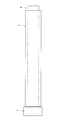
- FIG. 2 is a diagram illustrating a process of fixing the raw tube material to the cored bar.
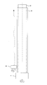
- FIG. 3 is a diagram illustrating a process of performing a spinning process.
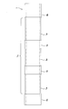
- FIG. 4 is a view showing the cylinder tube after the spinning process.
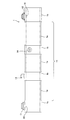
- FIG. 5 is a view showing a state in which the first supply / discharge port, the second supply / discharge port, and the holding member are attached to the cylinder tube.
- FIG. 1 is a plan view showing a fluid pressure cylinder 100 in the present embodiment.
- the fluid pressure cylinder 100 is used as an actuator that drives a drive unit such as a construction machine.
- the fluid pressure cylinder 100 uses oil as a working fluid.
- hydraulic fluid such as a water-soluble alternative liquid, or hydraulic gas may be used instead of oil.
- the fluid pressure cylinder 100 includes a cylindrical cylinder tube 1, a piston (not shown) that can slide in the cylinder tube 1 in the axial direction, one end connected to the piston, and the other end to the outside of the cylinder tube 1.
- a piston rod 2 that extends, a cylinder head 3 that slidably supports the piston rod 2, and a bottom member 4 that seals the cylinder tube 1.
- the piston has a first fluid pressure chamber (not shown) on one axial side (left side in FIG. 1) and a second fluid pressure chamber (not shown) on the other axial side (right side in FIG. 1) in the cylinder tube 1. ).
- the piston rod 2 has an eye part 21 at the end on the other axial side of the cylinder tube 1.
- the eye portion 21 has a circular through hole 21a having a central axis in a direction perpendicular to the axis of the piston rod 2, and the through hole 21a is connected to a drive unit such as a construction machine.
- the outer peripheral surface of the cylinder head 3 is screwed into the inner peripheral surface of the open end of the cylinder tube 1 on the side where the piston rod 2 extends. Further, the inner peripheral surface of the cylinder head 3 is in sliding contact with the outer peripheral surface of the piston rod 2.
- the bottom member 4 is welded and fixed to the opening end of the cylinder tube 1 opposite to the cylinder head 3.
- the bottom member 4 has an eye part 41 at the end of one side in the axial direction of the cylinder tube 1.
- the eye portion 41 has a circular through hole 41a having a central axis in a direction perpendicular to the axis of the cylinder tube 1, and the through hole 41a is connected to a drive unit such as a construction machine.
- the fluid pressure chamber in the cylinder tube 1 closed by the cylinder head 3 and the bottom member 4 is divided into a first fluid pressure chamber and a second fluid pressure chamber by the piston.
- the cylinder tube 1 is formed so as to penetrate from the outer peripheral surface to the inner peripheral surface in the vicinity of the bottom member 4 and from the outer peripheral surface to the inner peripheral surface in the vicinity of the cylinder head 3.
- Second through-holes 16 are provided.
- the first through hole 15 communicates with the first fluid pressure chamber, and the second through hole 16 communicates with the second fluid pressure chamber.
- the fluid pressure cylinder 100 is connected to the first supply / discharge port 11 that is welded and fixed to the outer peripheral surface of the cylinder tube 1 so as to be connected to the first through hole 15, and to the second through hole 16.
- a second supply / discharge port 12 that is welded and fixed to the outer peripheral surface of the tube 1, a pipe 13 that supplies / discharges working fluid pressure to / from the first supply / discharge port 11 and the second supply / discharge port 12, And a holding member 14 that is welded and fixed to the outer peripheral surface of the cylinder tube 1 so as to be held along 1.
- the working fluid pressure supplied from the pump (not shown) is controlled in flow rate and flow direction by a control valve (not shown), and is supplied to the first supply / discharge port 11 and the second supply / discharge port 12 via the pipe 13. It is supplied and discharged.
- the thickness of the raw pipe material is the first supply / discharge port 11, the second supply / discharge port 12, and the holding member that require strength. It sets so that sufficient intensity
- the portion of the outer peripheral surface of the cylinder tube 1 that does not require a large strength is thinned to reduce the weight.
- the wall thickness is changed by applying a spinning process (also referred to as a flow forming process) to the corresponding part.
- FIG. 2 is a diagram showing a process of fixing the raw tube material 5 to the cored bar 6.
- the raw tube material 5 has a cylindrical shape having a uniform outer diameter and inner diameter, that is, a uniform thickness.
- One end of the metal core 6 is connected to the rotary drive body 7, and the outer diameter is set to be substantially the same as the inner diameter of the raw tube 5.
- the raw material 5 is fitted from the other end side of the cored bar 6 until it comes into contact with the rotary drive body 7.
- FIG. 3 is a diagram showing a process of performing a spinning process.
- the roller 8 is moved in the axial direction of the raw tube material 5 while the roller 8 is pressed against the outer peripheral surface of the raw tube material 5. Thereby, the raw pipe material 5 is squeezed and stretched in the axial direction of the roller 8, and an area where the thickness of the raw pipe material 5 is thin is extended in the axial direction.
- FIG. 4 is a view showing the cylinder tube 1 after the spinning process.
- the small-diameter portion 1 a thinned by spinning and the large-diameter portion 1 b not spun are alternately formed.
- Large-diameter portions 1b are formed at both ends in the axial direction of the cylinder tube 1, and two large-diameter portions 1b are formed in the intermediate region 1c inside the both axial ends of the cylinder tube 1.
- three small-diameter portions 1a whose outer diameters are reduced by spinning are formed.
- FIG. 5 is a view showing a state in which the first supply / discharge port 11, the second supply / discharge port 12 and the holding member 14 are attached to the cylinder tube 1.
- a first through hole 15 and a second through hole 16 are formed at both ends in the axial direction of the cylinder tube 1 in which the large diameter portion 1b is formed, and the first supply / discharge port 11 and the second supply / discharge port 12 are welded. Fixed.
- a holding member 14 that holds the pipe 13 is welded and fixed to the two large-diameter portions 1b formed in the intermediate region 1c on the inner side from both axial end portions of the cylinder tube 1.
- a fluid pressure cylinder 100 shown in FIG. 1 is manufactured by fixing the bottom member 4 to the cylinder tube 1 manufactured in this way and welding the cylinder head 3 thereto.
- the cylinder tube 1 Since three small-diameter portions 1a whose outer diameter is reduced by spinning processing are formed in the intermediate region 1c on the inner side from both axial end portions of the cylinder tube 1, the cylinder tube 1 is thinned in places where large strength is not required. It is possible to reduce the weight while maintaining the strength of the cylinder tube 1.
- first supply / discharge port 11 and the second supply / discharge port 12 are fixed by welding to the large-diameter portion 1b formed on the outer peripheral surface of both ends in the axial direction of the cylinder tube 1, the strength of the cylinder tube 1 is sufficient. Can be secured.
- the holding member 14 is fixed by welding to the two large diameter portions 1b provided between the small diameter portions 1a of the intermediate region 1c, the strength of the cylinder tube 1 can be sufficiently ensured.
- the roller 8 pressed against the raw tube material 5 during the spinning process is moved in the axial direction.
- the raw tube material 5 may be moved in the axial direction, or the roller 8 and the raw tube material 5 may be moved. Both may be moved relative to each other in the axial direction.
- the number of the small diameter parts 1a may be two, and may be four or more.
Landscapes
- Engineering & Computer Science (AREA)
- Mechanical Engineering (AREA)
- Physics & Mathematics (AREA)
- Fluid Mechanics (AREA)
- General Engineering & Computer Science (AREA)
- Actuator (AREA)
- Pistons, Piston Rings, And Cylinders (AREA)
- Shaping Metal By Deep-Drawing, Or The Like (AREA)
Abstract
Description
Claims (5)
- シリンダチューブへの流体圧の給排に応じて伸縮作動する流体圧シリンダであって、
前記シリンダチューブの軸方向両端部より内側には、スピニング加工によって前記軸方向両端部より小径な少なくとも1つの小径部が形成される、
流体圧シリンダ。 - 請求項1に記載の流体圧シリンダであって、
前記軸方向両端部の外周面に設けられ、前記シリンダチューブ内に流体圧を給排する給排ポートをさらに備える、
流体圧シリンダ。 - 請求項1に記載の流体圧シリンダであって、
前記小径部は、前記シリンダチューブの軸方向に所定の間隔をあけて複数形成される、
流体圧シリンダ。 - 請求項3に記載の流体圧シリンダであって、
前記複数の小径部間の外周面に設けられ、前記シリンダチューブ内に流体圧を給排する配管を保持する保持部材をさらに備える、
流体圧シリンダ。 - シリンダチューブへの流体圧の給排に応じて伸縮作動する流体圧シリンダの製造方法であって、
前記シリンダチューブ内に芯金を嵌挿する工程と、
前記シリンダチューブを回転させ、従動回転するローラを前記シリンダチューブの外周面に対して押し当てながら、前記シリンダチューブと前記ローラとを前記シリンダチューブの軸方向に相対移動させ、前記シリンダチューブの外径を縮径させるスピニング加工を行う工程と、
を含み、
前記スピニング加工を行う工程は、前記シリンダチューブの軸方向両端部より内側に、前記スピニング加工によって前記軸方向両端部より小径な少なくとも1つの小径部を形成する、
流体圧シリンダの製造方法。
Priority Applications (4)
| Application Number | Priority Date | Filing Date | Title |
|---|---|---|---|
| CN201380074413.8A CN105008726B (zh) | 2013-03-21 | 2013-12-02 | 流体压缸及其制造方法 |
| EP13878874.0A EP2952751B1 (en) | 2013-03-21 | 2013-12-02 | Fluid pressure cylinder and method of manufacturing the cylinder |
| KR1020157023257A KR101597950B1 (ko) | 2013-03-21 | 2013-12-02 | 유체압 실린더 및 그 제조 방법 |
| US14/777,943 US20160281749A1 (en) | 2013-03-21 | 2013-12-02 | Fluid pressure cylinder and method of manufacturing the cylinder |
Applications Claiming Priority (2)
| Application Number | Priority Date | Filing Date | Title |
|---|---|---|---|
| JP2013058509A JP5768081B2 (ja) | 2013-03-21 | 2013-03-21 | 流体圧シリンダ及びその製造方法 |
| JP2013-058509 | 2013-03-21 |
Publications (1)
| Publication Number | Publication Date |
|---|---|
| WO2014147894A1 true WO2014147894A1 (ja) | 2014-09-25 |
Family
ID=51579605
Family Applications (1)
| Application Number | Title | Priority Date | Filing Date |
|---|---|---|---|
| PCT/JP2013/082362 Ceased WO2014147894A1 (ja) | 2013-03-21 | 2013-12-02 | 流体圧シリンダ及びその製造方法 |
Country Status (6)
| Country | Link |
|---|---|
| US (1) | US20160281749A1 (ja) |
| EP (1) | EP2952751B1 (ja) |
| JP (1) | JP5768081B2 (ja) |
| KR (1) | KR101597950B1 (ja) |
| CN (1) | CN105008726B (ja) |
| WO (1) | WO2014147894A1 (ja) |
Families Citing this family (3)
| Publication number | Priority date | Publication date | Assignee | Title |
|---|---|---|---|---|
| GB2552815B (en) | 2016-08-10 | 2018-12-26 | Impcross Ltd | Method of manufacturing a tubular member |
| US20240280203A1 (en) * | 2021-08-18 | 2024-08-22 | Bümach Engineering International B. V. | Cylinder pipe assembly and method for producing the same |
| CN114876910B (zh) * | 2022-06-17 | 2025-03-11 | 湖州环丰机械有限公司 | 一种轻量化变幅油缸 |
Citations (6)
| Publication number | Priority date | Publication date | Assignee | Title |
|---|---|---|---|---|
| JPH0455029A (ja) * | 1990-06-21 | 1992-02-21 | Chuo Seiki Kk | ホイール用リムの製造方法 |
| JPH0656506U (ja) * | 1993-01-20 | 1994-08-05 | カヤバ工業株式会社 | 油圧シリンダの配管固定構造 |
| JPH0791408A (ja) * | 1993-09-22 | 1995-04-04 | Smc Corp | 分離形流体圧シリンダ |
| JP2008051194A (ja) | 2006-08-24 | 2008-03-06 | Hokuto Kenki Service Kk | 油圧シリンダ及び油圧駆動装置 |
| JP2008057606A (ja) * | 2006-08-30 | 2008-03-13 | Kayaba Ind Co Ltd | 流体圧シリンダ及び配管固定構造 |
| JP2011045923A (ja) * | 2009-08-28 | 2011-03-10 | Sumitomo Metal Ind Ltd | 差厚金属板及びその製造方法 |
Family Cites Families (12)
| Publication number | Priority date | Publication date | Assignee | Title |
|---|---|---|---|---|
| US4508015A (en) * | 1983-07-29 | 1985-04-02 | Weihwang Lin | Hydraulic cylinder |
| JPH0656506B2 (ja) * | 1985-04-26 | 1994-07-27 | キヤノン株式会社 | トナ− |
| US4878419A (en) * | 1988-06-27 | 1989-11-07 | Allied-Signal Inc. | Lightweight hydraulic actuator |
| JPH0791408B2 (ja) * | 1990-12-20 | 1995-10-04 | 日立化成工業株式会社 | 発泡性熱可塑性樹脂粒子及び発泡成形品 |
| JPH05208234A (ja) * | 1992-01-31 | 1993-08-20 | Nhk Spring Co Ltd | 端部厚肉管の製造装置 |
| JPH09196005A (ja) * | 1996-01-22 | 1997-07-29 | Isuzu Motors Ltd | マスタシリンダ装置 |
| JP4354133B2 (ja) * | 2001-08-10 | 2009-10-28 | カヤバ工業株式会社 | シリンダの加工方法 |
| JP4560670B2 (ja) * | 2003-06-18 | 2010-10-13 | カヤバ工業株式会社 | アルミニウム合金パイプ材のスピニング加工方法 |
| DE102008027226A1 (de) * | 2008-06-06 | 2009-12-10 | Stabilus Gmbh | Druckmittelanschluss und ein mit diesem versehenes Kolben-Zylinderaggregat |
| CN101507967A (zh) * | 2009-03-19 | 2009-08-19 | 南通贝特医药机械有限公司 | 液流贯通式伸缩气缸 |
| JP5308961B2 (ja) * | 2009-08-27 | 2013-10-09 | カヤバ工業株式会社 | 流体圧シリンダ |
| US9803663B2 (en) * | 2011-10-27 | 2017-10-31 | Parker-Hannifin Corporation | Telescoping fluid porting tube |
-
2013
- 2013-03-21 JP JP2013058509A patent/JP5768081B2/ja active Active
- 2013-12-02 CN CN201380074413.8A patent/CN105008726B/zh active Active
- 2013-12-02 WO PCT/JP2013/082362 patent/WO2014147894A1/ja not_active Ceased
- 2013-12-02 EP EP13878874.0A patent/EP2952751B1/en active Active
- 2013-12-02 KR KR1020157023257A patent/KR101597950B1/ko active Active
- 2013-12-02 US US14/777,943 patent/US20160281749A1/en not_active Abandoned
Patent Citations (6)
| Publication number | Priority date | Publication date | Assignee | Title |
|---|---|---|---|---|
| JPH0455029A (ja) * | 1990-06-21 | 1992-02-21 | Chuo Seiki Kk | ホイール用リムの製造方法 |
| JPH0656506U (ja) * | 1993-01-20 | 1994-08-05 | カヤバ工業株式会社 | 油圧シリンダの配管固定構造 |
| JPH0791408A (ja) * | 1993-09-22 | 1995-04-04 | Smc Corp | 分離形流体圧シリンダ |
| JP2008051194A (ja) | 2006-08-24 | 2008-03-06 | Hokuto Kenki Service Kk | 油圧シリンダ及び油圧駆動装置 |
| JP2008057606A (ja) * | 2006-08-30 | 2008-03-13 | Kayaba Ind Co Ltd | 流体圧シリンダ及び配管固定構造 |
| JP2011045923A (ja) * | 2009-08-28 | 2011-03-10 | Sumitomo Metal Ind Ltd | 差厚金属板及びその製造方法 |
Non-Patent Citations (1)
| Title |
|---|
| See also references of EP2952751A4 |
Also Published As
| Publication number | Publication date |
|---|---|
| EP2952751A1 (en) | 2015-12-09 |
| EP2952751B1 (en) | 2018-06-27 |
| JP2014181806A (ja) | 2014-09-29 |
| CN105008726B (zh) | 2017-02-15 |
| JP5768081B2 (ja) | 2015-08-26 |
| KR101597950B1 (ko) | 2016-02-26 |
| CN105008726A (zh) | 2015-10-28 |
| EP2952751A4 (en) | 2017-01-18 |
| KR20150103334A (ko) | 2015-09-09 |
| US20160281749A1 (en) | 2016-09-29 |
Similar Documents
| Publication | Publication Date | Title |
|---|---|---|
| WO2013065457A1 (ja) | 流体圧シリンダ及びその製造方法 | |
| WO2017073439A1 (ja) | 流体制御弁 | |
| JP5768081B2 (ja) | 流体圧シリンダ及びその製造方法 | |
| JP6611544B2 (ja) | 接合体、流体圧シリンダ、及び接合体の製造方法 | |
| WO2014174966A1 (ja) | チューブおよび緩衝器 | |
| WO2013137235A1 (ja) | 切換バルブ | |
| JP6371694B2 (ja) | 可変容量型ポンプ | |
| US20160186868A1 (en) | Valve device | |
| US9995323B2 (en) | Drive unit of a fluid-actuated linear drive and method for its manufacture | |
| JP6275459B2 (ja) | 流体圧シリンダ | |
| CN103754675A (zh) | 内衬纸卷筒装夹支架及装夹方法 | |
| JPWO2013129589A1 (ja) | シリンダ装置の製造方法 | |
| JP2014181806A5 (ja) | ||
| EP2829742B1 (en) | Hydraulic cylinder | |
| CN113231700B (zh) | 一种建筑施工用套丝机板牙机构 | |
| CN115889308B (zh) | 清洗机械臂以及清洗设备 | |
| JP7176506B2 (ja) | 流体切替弁 | |
| RU2018112824A (ru) | Способ демонтажа опорных втулок осей машин из глухих отверстий | |
| CN105229313A (zh) | 流体压力缸 | |
| CN104776075B (zh) | 液压阀和包括该液压阀的装载机 | |
| WO2020137077A1 (ja) | スピニング加工装置、スピニング加工方法、加工ローラ | |
| CN106151153A (zh) | 四工位单作用液压缸 | |
| WO2016098619A1 (ja) | 耐圧機器 | |
| JP2010151051A (ja) | 可変容量型油圧ポンプの傾転制御装置 | |
| JP6571489B2 (ja) | 油圧ダウンザホールドリルのアキュムレータ装置 |
Legal Events
| Date | Code | Title | Description |
|---|---|---|---|
| 121 | Ep: the epo has been informed by wipo that ep was designated in this application |
Ref document number: 13878874 Country of ref document: EP Kind code of ref document: A1 |
|
| ENP | Entry into the national phase |
Ref document number: 20157023257 Country of ref document: KR Kind code of ref document: A |
|
| WWE | Wipo information: entry into national phase |
Ref document number: 2013878874 Country of ref document: EP |
|
| WWE | Wipo information: entry into national phase |
Ref document number: 14777943 Country of ref document: US |
|
| NENP | Non-entry into the national phase |
Ref country code: DE |