WO2014147982A1 - Dispositif de rapport d'urgence monté sur véhicule - Google Patents
Dispositif de rapport d'urgence monté sur véhicule Download PDFInfo
- Publication number
- WO2014147982A1 WO2014147982A1 PCT/JP2014/001204 JP2014001204W WO2014147982A1 WO 2014147982 A1 WO2014147982 A1 WO 2014147982A1 JP 2014001204 W JP2014001204 W JP 2014001204W WO 2014147982 A1 WO2014147982 A1 WO 2014147982A1
- Authority
- WO
- WIPO (PCT)
- Prior art keywords
- battery
- vehicle
- voltage
- emergency call
- warning
- Prior art date
- Legal status (The legal status is an assumption and is not a legal conclusion. Google has not performed a legal analysis and makes no representation as to the accuracy of the status listed.)
- Ceased
Links
Images






Classifications
-
- G—PHYSICS
- G08—SIGNALLING
- G08B—SIGNALLING SYSTEMS, e.g. PERSONAL CALLING SYSTEMS; ORDER TELEGRAPHS; ALARM SYSTEMS
- G08B23/00—Alarms responsive to unspecified undesired or abnormal conditions
-
- B—PERFORMING OPERATIONS; TRANSPORTING
- B60—VEHICLES IN GENERAL
- B60R—VEHICLES, VEHICLE FITTINGS, OR VEHICLE PARTS, NOT OTHERWISE PROVIDED FOR
- B60R21/00—Arrangements or fittings on vehicles for protecting or preventing injuries to occupants or pedestrians in case of accidents or other traffic risks
-
- G—PHYSICS
- G08—SIGNALLING
- G08B—SIGNALLING SYSTEMS, e.g. PERSONAL CALLING SYSTEMS; ORDER TELEGRAPHS; ALARM SYSTEMS
- G08B25/00—Alarm systems in which the location of the alarm condition is signalled to a central station, e.g. fire or police telegraphic systems
- G08B25/01—Alarm systems in which the location of the alarm condition is signalled to a central station, e.g. fire or police telegraphic systems characterised by the transmission medium
- G08B25/016—Personal emergency signalling and security systems
-
- G—PHYSICS
- G08—SIGNALLING
- G08B—SIGNALLING SYSTEMS, e.g. PERSONAL CALLING SYSTEMS; ORDER TELEGRAPHS; ALARM SYSTEMS
- G08B19/00—Alarms responsive to two or more different undesired or abnormal conditions, e.g. burglary and fire, abnormal temperature and abnormal rate of flow
-
- G—PHYSICS
- G08—SIGNALLING
- G08B—SIGNALLING SYSTEMS, e.g. PERSONAL CALLING SYSTEMS; ORDER TELEGRAPHS; ALARM SYSTEMS
- G08B21/00—Alarms responsive to a single specified undesired or abnormal condition and not otherwise provided for
- G08B21/18—Status alarms
- G08B21/182—Level alarms, e.g. alarms responsive to variables exceeding a threshold
-
- G—PHYSICS
- G08—SIGNALLING
- G08B—SIGNALLING SYSTEMS, e.g. PERSONAL CALLING SYSTEMS; ORDER TELEGRAPHS; ALARM SYSTEMS
- G08B25/00—Alarm systems in which the location of the alarm condition is signalled to a central station, e.g. fire or police telegraphic systems
- G08B25/01—Alarm systems in which the location of the alarm condition is signalled to a central station, e.g. fire or police telegraphic systems characterised by the transmission medium
- G08B25/10—Alarm systems in which the location of the alarm condition is signalled to a central station, e.g. fire or police telegraphic systems characterised by the transmission medium using wireless transmission systems
-
- H—ELECTRICITY
- H04—ELECTRIC COMMUNICATION TECHNIQUE
- H04M—TELEPHONIC COMMUNICATION
- H04M1/00—Substation equipment, e.g. for use by subscribers
- H04M1/72—Mobile telephones; Cordless telephones, i.e. devices for establishing wireless links to base stations without route selection
- H04M1/724—User interfaces specially adapted for cordless or mobile telephones
- H04M1/72448—User interfaces specially adapted for cordless or mobile telephones with means for adapting the functionality of the device according to specific conditions
- H04M1/72454—User interfaces specially adapted for cordless or mobile telephones with means for adapting the functionality of the device according to specific conditions according to context-related or environment-related conditions
-
- B—PERFORMING OPERATIONS; TRANSPORTING
- B60—VEHICLES IN GENERAL
- B60R—VEHICLES, VEHICLE FITTINGS, OR VEHICLE PARTS, NOT OTHERWISE PROVIDED FOR
- B60R21/00—Arrangements or fittings on vehicles for protecting or preventing injuries to occupants or pedestrians in case of accidents or other traffic risks
- B60R2021/0027—Post collision measures, e.g. notifying emergency services
-
- B—PERFORMING OPERATIONS; TRANSPORTING
- B60—VEHICLES IN GENERAL
- B60R—VEHICLES, VEHICLE FITTINGS, OR VEHICLE PARTS, NOT OTHERWISE PROVIDED FOR
- B60R21/00—Arrangements or fittings on vehicles for protecting or preventing injuries to occupants or pedestrians in case of accidents or other traffic risks
- B60R21/01—Electrical circuits for triggering passive safety arrangements, e.g. airbags, safety belt tighteners, in case of vehicle accidents or impending vehicle accidents
- B60R2021/0104—Communication circuits for data transmission
- B60R2021/01081—Transmission medium
- B60R2021/01088—Transmission medium wireless
-
- G—PHYSICS
- G08—SIGNALLING
- G08B—SIGNALLING SYSTEMS, e.g. PERSONAL CALLING SYSTEMS; ORDER TELEGRAPHS; ALARM SYSTEMS
- G08B25/00—Alarm systems in which the location of the alarm condition is signalled to a central station, e.g. fire or police telegraphic systems
- G08B25/14—Central alarm receiver or annunciator arrangements
Definitions
- This disclosure relates to an in-vehicle emergency call device having a function of transmitting an emergency call signal to a center device.
- the in-vehicle emergency call device installed in the vehicle has a backup battery made up of a rechargeable battery such as a lithium ion battery, and can be operated by the backup battery even when the vehicle battery is damaged due to a traffic accident or the like. ing.
- a backup battery made up of a rechargeable battery such as a lithium ion battery
- the backup battery is exhausted and the battery runs out, the emergency call operation cannot be performed suddenly.
- the voltage of the backup battery is detected, and when the detected voltage falls below a predetermined reference voltage value, the backup battery is warned in advance.
- the backup battery since the backup battery has a characteristic that the discharge performance is lowered in a low temperature environment, the backup battery is likely to run out in a low temperature environment.
- the backup battery voltage starts to rise when the emergency call operation continues even after the backup battery voltage falls below the specified reference voltage value and the backup battery has run out.
- the battery performance may be recovered by exceeding the reference voltage value. If there is a possibility that the battery performance may be recovered in this way, performing warning control that warns immediately when the detected voltage of the backup battery falls below the reference voltage value will result in sufficient battery discharge performance remaining. Regardless, an emergency call operation must be stopped.
- an object of the present disclosure is to provide an in-vehicle emergency call device that can accurately detect a decrease in the discharge performance of a backup battery.
- the in-vehicle emergency call device has a function of transmitting an emergency call signal to the center device through the communication network when it is determined that the vehicle has collided, and is supplied from the vehicle battery. It is configured to operate using electric power as operating power.
- the in-vehicle emergency call device includes a backup battery that supplies operating power of the in-vehicle emergency call device when the power supplied from the vehicle battery decreases, a voltage detection unit that detects the voltage of the backup battery, A first determination unit for determining whether or not the voltage detected by the voltage detection unit is lower than a threshold value for battery exhaustion warning, and a second order differential coefficient obtained by secondarily differentiating the battery voltage function with respect to time is negative A second determination unit for determining whether or not there is a battery exhaustion warning when the detected voltage is lower than a threshold for battery exhaustion warning and the second derivative is negative; And a warning unit that issues a battery exhaustion warning when the secondary differential coefficient is positive. According to this configuration, it is possible to accurately detect a decrease in the discharge performance of the backup battery.
- FIG. 1 is a functional block diagram schematically showing the overall configuration of the emergency call system of the present embodiment.
- the emergency call system 1 is configured such that an in-vehicle emergency call device 2 mounted on a vehicle and a center device 3 installed in a service center can communicate with each other through a communication network 4.
- the communication network 4 here includes a mobile communication network and a fixed communication network.
- the in-vehicle emergency call device 2 includes a CPU 5, a wireless communication unit 6, a GPS positioning unit 7, a memory management unit 8, a voice processing unit 9, a collision detection unit 10, a timer management unit 11, a power supply control unit 12, a peripheral device processing unit 13, and The vehicle LAN control unit 14 is provided.
- the CPU 5 executes a control program to control the overall operation of the in-vehicle emergency call device 2, and has a function as a control unit.
- the wireless communication unit 6 controls wireless communication performed with the center device 3 through the communication network 4 and switches between voice communication and data communication with the communication line connected, and is disposed in the vehicle occupant and the service center. Voice communication and data communication can be made with an operator.
- the wireless communication unit 6 has a function as a transmission output setting unit that variably controls the magnitude of transmission power of wireless communication in accordance with a control signal from the CPU 5.
- the GPS positioning unit 7 When the GPS positioning unit 7 receives a GPS signal transmitted from a GPS satellite, the GPS positioning unit 7 calculates a parameter extracted from the GPS signal and acquires a vehicle position (measures).
- the memory management unit 8 stores and manages various types of memory information, and stores and manages occupant information (user information), vehicle information, the vehicle position acquired by the GPS positioning unit 7 described above, and the like.
- the voice processing unit 9 performs voice processing on the transmitted voice input from the microphone 15 and voice-processes the received voice and outputs it from the speaker 16.
- the voice processing unit 9 has a function as a voice output setting unit that variably controls the magnitude of the voice output of the received voice (call voice) according to the control signal from the CPU 5.
- the timer management unit 11 starts timing when a timing start signal is input from the CPU 5, and outputs a timing end signal to the CPU 5 when the timing of a predetermined time defined in advance is ended (when time is up).
- the power supply control unit 12 has a function of operating the in-vehicle emergency call device 2 by supplying power supplied from the vehicle battery 17 mounted on the vehicle as operating power to each functional block.
- the power control unit 12 includes a power generation unit 18, a backup battery 19, a charging unit 20, and a battery voltage detection unit (voltage detection unit, voltage detection unit) 21.
- the power generation unit 18 generates power to be supplied to each functional block using the power supplied from the vehicle battery 17 as operating power and supplies the generated power to each functional block. Then, when the vehicle battery 17 is damaged, that is, when the power is not supplied from the vehicle battery 17 or when the power supply is reduced, the power generation unit 18 uses the power supplied from the backup battery 19 as the operating power. Electric power to be supplied to each functional block is generated and supplied to each functional block.
- the backup battery 19 is composed of a rechargeable battery such as a lithium ion battery or a nickel metal hydride battery, and is configured to be charged via the charging unit 20 with electric power supplied from the vehicle battery 17.
- the battery voltage detection unit 21 detects, for example, a voltage as the battery capacity (battery capacity, discharge performance) of the backup battery 19 and outputs the detected voltage detection signal to the CPU 5.
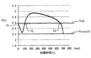
- the CPU 5 can sequentially store the detected voltage value of the backup battery 19 in a memory (for example, the memory management unit 8) at a predetermined sampling period (for example, every 1 second or 0.5 seconds). It has a function of calculating a detection voltage function V (t) (battery voltage function V (t)) based on a predetermined number of detection voltage values V (t n ).
- the characteristic diagram of the detection voltage function V (t) (curve of the detection voltage value V (t n )) is, for example, a characteristic diagram as shown in FIG. In FIG. 3, the horizontal axis indicates the discharge time t, and the vertical axis indicates the detection voltage V (t) (detection voltage value V (t n )).
- the CPU 5 has a function of calculating a primary differential function d / dt (V (t)) obtained by differentiating the detected voltage function V (t) with respect to time t.
- the characteristic diagram (curve of the primary differential function) of the primary differential function d / dt (V (t)) is, for example, a characteristic diagram as shown in FIG. In FIG. 4, the horizontal axis represents the discharge time t, and the vertical axis represents the first-order differential function d / dt (V (t)) of the detected voltage function V (t).
- the CPU 5 calculates a secondary differential function d 2 / d 2 t (V (t)) obtained by differentiating the primary differential function d / dt (V (t)) with time t (that is, the detection described above).
- a characteristic diagram of the secondary differential function d 2 / d 2 t (V (t)) (curve of the secondary differential function) is, for example, a characteristic diagram as shown in FIG. In FIG. 5, the horizontal axis represents the discharge time t, and the vertical axis represents the secondary differential function d 2 / d 2 t (V (t)) of the detected voltage function V (t).
- the peripheral device processing unit 13 is connected to an airbag ECU 22, a Mayday switch 23, a power switch 24 and a pre-crash safety ECU 25.
- the airbag ECU 22 is connected to an airbag (not shown), and is operable on condition that the input of the IG (ignition) signal output from the power switch 24 is on, and the airbag is deployed. Then, an airbag deployment signal is output.
- the Mayday switch 23 outputs an operation detection signal when operated by a passenger.
- the power switch 24 includes an IG switch and an ACC (accessory) switch, and outputs an IG signal indicating ON / OFF of the IG switch and an ACC signal indicating ON / OFF of the ACC switch.
- the pre-crash safety ECU 25 is connected to a camera 26, a millimeter wave radar 27, a vehicle speed sensor 28, a rudder angle sensor 29, a brake control ECU 30, an air suspension ECU 31, and a seat belt ECU 32.
- the pre-crash safety ECU 25 is operable on condition that the input of the IG signal output from the power switch 24 is on. For example, a video signal input from the camera 26, a radar detection signal input from the millimeter wave radar 27, The vehicle speed signal input from the vehicle speed sensor 28 and the steering angle signal indicating the steering angle of the steering wheel 33 input from the steering angle sensor 29 are analyzed to determine whether or not the vehicle may collide with a preceding vehicle or an obstacle. To do. In this case, if the pre-crash safety ECU 25 determines that the vehicle may collide, it outputs a pre-crash detection signal.
- the brake actuator 34 is operated through the brake control ECU 30, the air suspension 35 is operated through the air suspension ECU 31, and the seat belt 36 is wound up through the seat belt ECU 32.
- the pre-crash safety ECU 25 is also connected to a combination meter (not shown), and if it is determined that the vehicle may collide, a warning indicating that the vehicle may collide is displayed on the combination meter. Display.
- the vehicle LAN control unit 14 connects a navigation device 37, a meter device 38, an alarm device 39, and an engine control device 40 through a vehicle LAN 41, and transmits and receives various signals to and from these devices 37 to 40.
- the operation of 37 to 40 is controlled.
- the alarm device 39 is connected to a horn 42, a headlight 43, and a hazard lamp 44.
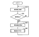
- FIGS. 6 and 7 show the control contents of the in-vehicle emergency call device 2.
- the operation when the battery capacity, for example, the voltage of the backup battery 19 of the emergency call device 2 in the low temperature (below freezing) environment is reduced will be described based on the characteristic diagram of FIG.
- Vth predetermined reference voltage value
- the detected voltage starts to rise before reaching the voltage value Vcutoff (set voltage value, for example, 2.2 V), and exceeds the threshold value Vth for battery exhaustion warning. I know it will last long.
- the backup battery 19 can still be used if a battery exhaustion warning is issued between the time T1 and the time T2 (a state where the detected voltage is equal to or lower than the battery exhaustion warning threshold Vth).
- the present inventor has a function d 2 / d 2 obtained by secondarily differentiating the detection voltage function V (t) of the backup battery 19 with respect to time t in order to distinguish between time T1 and time T2 and after time T3. It was invented that by examining whether t (V (t)) is positive or negative, it is possible to distinguish between time T1 and T2 and after time T3. Specifically, the second order differential function d 2 / d 2 t (V (t)) is not negative (becomes positive) from time T1 to T2, that is, the curve shape of the detected voltage function V (t). Becomes a convex shape.
- a vehicle collision detection process is executed.
- a pre-crash detection signal is output from the pre-crash safety ECU 25
- the possibility of a vehicle collision is determined in response to this, and the radio communication unit 6 of the in-vehicle emergency call device 2 and the center device 3 are determined.
- Wireless communication lines are connected.
- the airbag deployment signal is output from the airbag ECU 22
- the process proceeds to S30, and the emergency call process is started.
- Information transmitted from the in-vehicle emergency call device 2 to the center device 3 by this emergency call processing includes occupant information, vehicle information, latest vehicle position information, and the like.
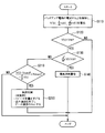
- the process proceeds to S40, and a process for determining the battery capacity of the backup battery 19 is executed. Specifically, the process proceeds to S110 in FIG. 7, and the battery voltage detector 21 detects the voltage of the backup battery 19 and stores the detected voltage value (V (t n )).
- V (t n ) the detection voltage function
- S40 is executed for the first time after the power is turned on. In this case, voltage detection is continued at a predetermined sampling period (for example, 1 second) until the set number of detected voltage values (V (t n )) are stored. If the set number of detection voltage values (V (t n )) has already been stored, the voltage detection is performed once and this detection value is stored.
- the set number of detected voltage values (V (t n )) stored specifically, the set number of detected voltage values (V (t n )) including the latest detected voltage value (V (t n )). n )
- the detected voltage function V (t) is calculated and stored in the memory.
- the oldest detection voltage value (V (t n )) may be deleted from the memory (that is, a set number of detection voltage values (V (t n )) are always stored) or left.
- the detected voltage values (V (t)) of the set number or more may be stored and deleted when the memory becomes insufficient.
- a primary differential function d / dt (V (t)) obtained by differentiating the calculated detection voltage function V (t) with respect to time t is calculated and stored.
- a secondary differential function d 2 / d 2 t (V (t)) obtained by differentiating the calculated primary differential function d / dt (V (t)) with time t is calculated and stored.
- the process proceeds to S120, in which it is determined whether or not the latest detected voltage value (V (t n )) is lower than (less than) the threshold value Vth for battery exhaustion warning (first determination unit). As a function).
- the latest detected voltage value (V (t n )) is not lower than the threshold value Vth for battery exhaustion warning (S120: NO)
- the battery capacity determination process is terminated.
- the battery capacity determination process (S40 in FIG. 6, ie, S110 to S140 in FIG. 7) is configured to be executed at set time intervals (for example, every 1 second or 10 seconds).
- the second order differential function d 2 / d 2 t (V (t)) (that is, When the secondary differential coefficient d 2 / d 2 t (V (t n ))) is not negative (when the discharge performance of the backup battery 19 is restored), the battery differential warning d is not issued.
- the battery differential warning d is not issued.
- 2 / d 2 t (V (t)) is negative (when the discharge performance of the backup battery 19 does not recover)
- the battery is warned, so the discharge performance of the backup battery 19 is degraded. Can be detected accurately.
- FIG. 8 illustrates a second embodiment of the present disclosure.
- the same sections or steps as those in the first embodiment are given the same numbers.
- the secondary differential function d 2 / d 2 t (V (t)) is not negative (S130: NO)
- the estimated time until the backup battery 19 becomes inoperative is calculated
- the calculation time is smaller than the set value Tdown, the load is reduced to prevent the backup battery 19 from being inactivated as much as possible.
- the processing from S110 to S130 is the same as in the first embodiment (see FIG. 7).
- the process proceeds to S210.
- the estimated time until the backup battery 19 is deactivated is calculated, and it is determined whether or not this calculated time is smaller than the set value Tdown.
- the predicted time is calculated as follows: (current detection voltage value V (t) ⁇ voltage value Vcutoff at which the battery is inoperative) obtained from a first-order differential function d / dt (V (t)) ⁇ d It can be calculated by dividing by / dt (V (t)) (see FIG. 9, function as calculation unit).
- S210 when the predicted time is smaller than the set value Tdown (S210: YES), the process proceeds to S220.
- the load is reduced to prevent the backup battery 19 from being inactivated as much as possible (function as a load reducing unit). Specifically, the volume of the speaker 15 is reduced (call voice output reduction), or the voice call is terminated and only data communication is executed. Then, the battery capacity determination process ends.
- the battery capacity determination process is terminated.
- the detection voltage V (t) is lower than the threshold value Vth for battery exhaustion warning, and the secondary differential function d 2 / d 2 t (V (t)) is When it is not negative (S130: NO), the estimated time until the backup battery 19 becomes inoperative is calculated. When the calculated time is smaller than the set value Tdown, the load is reduced. It is possible to prevent 19 from becoming inoperative as much as possible.
- the call voice output reduction and the voice call function stop are executed.
- the present invention is not limited to this.
- the power reduction of the radio device of the in-vehicle emergency call device 2 may be executed, or other functions may be limited.
- each section is expressed as S100, for example.
- each section can be divided into a plurality of subsections, while a plurality of sections can be combined into one section.
- each section configured in this manner can be referred to as a device, module, or means.
Landscapes
- Engineering & Computer Science (AREA)
- Physics & Mathematics (AREA)
- General Physics & Mathematics (AREA)
- Business, Economics & Management (AREA)
- Emergency Management (AREA)
- Computer Networks & Wireless Communication (AREA)
- Mechanical Engineering (AREA)
- Computer Security & Cryptography (AREA)
- Signal Processing (AREA)
- Human Computer Interaction (AREA)
- Environmental & Geological Engineering (AREA)
- Alarm Systems (AREA)
- Traffic Control Systems (AREA)
- Emergency Alarm Devices (AREA)
Abstract
Priority Applications (3)
| Application Number | Priority Date | Filing Date | Title |
|---|---|---|---|
| US14/778,015 US9616835B2 (en) | 2013-03-21 | 2014-03-05 | Vehicle-mounted emergency report device |
| RU2015144861/12A RU2603558C1 (ru) | 2013-03-21 | 2014-03-05 | Установленное на транспортном средстве устройство экстренного сообщения |
| DE112014001548.2T DE112014001548B4 (de) | 2013-03-21 | 2014-03-05 | Fahrzeuggebundene Notfallmeldevorrichtung |
Applications Claiming Priority (2)
| Application Number | Priority Date | Filing Date | Title |
|---|---|---|---|
| JP2013058526A JP6089841B2 (ja) | 2013-03-21 | 2013-03-21 | 車載緊急通報装置 |
| JP2013-058526 | 2013-03-21 |
Publications (1)
| Publication Number | Publication Date |
|---|---|
| WO2014147982A1 true WO2014147982A1 (fr) | 2014-09-25 |
Family
ID=51579684
Family Applications (1)
| Application Number | Title | Priority Date | Filing Date |
|---|---|---|---|
| PCT/JP2014/001204 Ceased WO2014147982A1 (fr) | 2013-03-21 | 2014-03-05 | Dispositif de rapport d'urgence monté sur véhicule |
Country Status (5)
| Country | Link |
|---|---|
| US (1) | US9616835B2 (fr) |
| JP (1) | JP6089841B2 (fr) |
| DE (1) | DE112014001548B4 (fr) |
| RU (1) | RU2603558C1 (fr) |
| WO (1) | WO2014147982A1 (fr) |
Cited By (3)
| Publication number | Priority date | Publication date | Assignee | Title |
|---|---|---|---|---|
| JP2017087933A (ja) * | 2015-11-09 | 2017-05-25 | マツダ株式会社 | 緊急通報装置の配線構造 |
| RU2699074C1 (ru) * | 2016-04-19 | 2019-09-03 | Мазда Мотор Корпорейшн | Устройство экстренного оповещения и система экстренного оповещения |
| CN111784982A (zh) * | 2020-04-01 | 2020-10-16 | 北京京东尚科信息技术有限公司 | 电池安全预警系统、方法和物流包裹跟踪系统 |
Families Citing this family (3)
| Publication number | Priority date | Publication date | Assignee | Title |
|---|---|---|---|---|
| JP6079705B2 (ja) * | 2014-06-23 | 2017-02-15 | トヨタ自動車株式会社 | 車両用緊急通報装置 |
| JP2023177970A (ja) * | 2022-06-03 | 2023-12-14 | 株式会社デンソーテン | 通報装置および通報方法 |
| US12612034B2 (en) * | 2023-09-07 | 2026-04-28 | GM Global Technology Operations LLC | System and method for providing information to first responders after a vehicle collision |
Citations (5)
| Publication number | Priority date | Publication date | Assignee | Title |
|---|---|---|---|---|
| JPH08331769A (ja) * | 1995-05-31 | 1996-12-13 | Honda Motor Co Ltd | 2次電池の充電制御方法およびその装置 |
| JP2006343230A (ja) * | 2005-06-09 | 2006-12-21 | Mitsubishi Electric Corp | 蓄電池残存容量検出装置 |
| WO2009133726A1 (fr) * | 2008-04-28 | 2009-11-05 | ホーチキ株式会社 | Dispositif d’alarme |
| JP2011076358A (ja) * | 2009-09-30 | 2011-04-14 | Yamato Protec Co | 住宅用火災警報器 |
| JP2012247909A (ja) * | 2011-05-26 | 2012-12-13 | Sanyo Electric Co Ltd | 通報システム |
Family Cites Families (23)
| Publication number | Priority date | Publication date | Assignee | Title |
|---|---|---|---|---|
| SU907451A1 (ru) * | 1976-07-06 | 1982-02-23 | Предприятие П/Я В-2502 | Устройство дл сигнализации разр да источников питани посто нного тока |
| SU1115078A1 (ru) * | 1982-06-17 | 1984-09-23 | Истринское отделение Всесоюзного научно-исследовательского института электромеханики | Устройство дл контрол напр жени батареи (его варианты) |
| US5278509A (en) * | 1992-02-03 | 1994-01-11 | At&T Bell Laboratories | Method for monitoring battery discharge by determining the second derivative of battery voltage over time |
| US5341503A (en) | 1992-04-16 | 1994-08-23 | International Business Machines Corporation | Battery operated computer having improved battery gauge and system for measuring battery charge |
| JPH07243693A (ja) | 1994-03-04 | 1995-09-19 | Matsushita Electric Ind Co Ltd | 空気調和機の遠隔制御装置 |
| JPH09182311A (ja) | 1995-12-22 | 1997-07-11 | Honda Motor Co Ltd | バッテリの充電制御装置 |
| JP2001086654A (ja) | 1999-09-10 | 2001-03-30 | Mitsubishi Electric Corp | リチウム電池の活性化方法及びその回路 |
| JP4308408B2 (ja) | 2000-04-28 | 2009-08-05 | パナソニック株式会社 | 二次電池の入出力制御装置 |
| JP2003007354A (ja) | 2001-06-25 | 2003-01-10 | Toyota Motor Corp | リチウム二次電池の特性評価方法及び特性評価装置 |
| JP2003197271A (ja) | 2001-12-26 | 2003-07-11 | Ngk Insulators Ltd | リチウム二次電池の評価方法及びそれを用いたリチウム二次電池 |
| US7323848B2 (en) | 2002-12-11 | 2008-01-29 | Japan Storage Battery Co., Ltd. | Battery charging state arithmetic operation device for calculating charging state of battery, and battery charging state arithmetic operation method |
| JP3689084B2 (ja) | 2002-12-11 | 2005-08-31 | 三菱電機株式会社 | バッテリ充電状態演算装置およびバッテリ充電状態演算方法 |
| JP4016897B2 (ja) | 2003-06-27 | 2007-12-05 | トヨタ自動車株式会社 | 蓄電装置の充放電制御装置および自動車 |
| JP2007157665A (ja) | 2005-12-09 | 2007-06-21 | Casio Comput Co Ltd | バッテリ終止検出装置 |
| JP4784494B2 (ja) | 2006-11-24 | 2011-10-05 | 株式会社デンソー | 車載緊急通報装置 |
| FR2933539B1 (fr) | 2008-07-07 | 2011-02-25 | Cooltech Applications | Procede et dispositif de regulation thermique d'une batterie rechargeable de stockage d'energie electrique |
| US7956490B2 (en) * | 2009-09-16 | 2011-06-07 | Jack Sotnikow | Battery backup for vehicle emergency communicator |
| WO2011038764A1 (fr) * | 2009-09-30 | 2011-04-07 | Jentschura, Rolf | Système de contrôle de la position de pièces de véhicules |
| JP5094819B2 (ja) | 2009-11-18 | 2012-12-12 | シャープ株式会社 | 充電制御方法、充電制御コンピュータプログラム、充電制御装置、2次電池システム、2次電池電力源、および、電池応用装置 |
| JP5163689B2 (ja) * | 2010-05-11 | 2013-03-13 | 株式会社デンソー | 緊急通報用車載端末 |
| JP5327151B2 (ja) * | 2010-07-01 | 2013-10-30 | 株式会社デンソー | 緊急通報システム |
| JP2013058526A (ja) | 2011-09-07 | 2013-03-28 | Nagoya Institute Of Technology | 有機薄膜太陽電池 |
| JP5472396B2 (ja) * | 2011-10-27 | 2014-04-16 | 株式会社デンソー | 車載緊急通報装置 |
-
2013
- 2013-03-21 JP JP2013058526A patent/JP6089841B2/ja not_active Expired - Fee Related
-
2014
- 2014-03-05 US US14/778,015 patent/US9616835B2/en not_active Expired - Fee Related
- 2014-03-05 DE DE112014001548.2T patent/DE112014001548B4/de active Active
- 2014-03-05 RU RU2015144861/12A patent/RU2603558C1/ru active
- 2014-03-05 WO PCT/JP2014/001204 patent/WO2014147982A1/fr not_active Ceased
Patent Citations (5)
| Publication number | Priority date | Publication date | Assignee | Title |
|---|---|---|---|---|
| JPH08331769A (ja) * | 1995-05-31 | 1996-12-13 | Honda Motor Co Ltd | 2次電池の充電制御方法およびその装置 |
| JP2006343230A (ja) * | 2005-06-09 | 2006-12-21 | Mitsubishi Electric Corp | 蓄電池残存容量検出装置 |
| WO2009133726A1 (fr) * | 2008-04-28 | 2009-11-05 | ホーチキ株式会社 | Dispositif d’alarme |
| JP2011076358A (ja) * | 2009-09-30 | 2011-04-14 | Yamato Protec Co | 住宅用火災警報器 |
| JP2012247909A (ja) * | 2011-05-26 | 2012-12-13 | Sanyo Electric Co Ltd | 通報システム |
Cited By (3)
| Publication number | Priority date | Publication date | Assignee | Title |
|---|---|---|---|---|
| JP2017087933A (ja) * | 2015-11-09 | 2017-05-25 | マツダ株式会社 | 緊急通報装置の配線構造 |
| RU2699074C1 (ru) * | 2016-04-19 | 2019-09-03 | Мазда Мотор Корпорейшн | Устройство экстренного оповещения и система экстренного оповещения |
| CN111784982A (zh) * | 2020-04-01 | 2020-10-16 | 北京京东尚科信息技术有限公司 | 电池安全预警系统、方法和物流包裹跟踪系统 |
Also Published As
| Publication number | Publication date |
|---|---|
| US20160144816A1 (en) | 2016-05-26 |
| JP6089841B2 (ja) | 2017-03-08 |
| DE112014001548T5 (de) | 2015-12-24 |
| JP2014182747A (ja) | 2014-09-29 |
| RU2603558C1 (ru) | 2016-11-27 |
| DE112014001548B4 (de) | 2024-07-25 |
| US9616835B2 (en) | 2017-04-11 |
Similar Documents
| Publication | Publication Date | Title |
|---|---|---|
| JP5472396B2 (ja) | 車載緊急通報装置 | |
| US11254333B2 (en) | Electronic control device, vehicle control method, and vehicle control program product | |
| JP6089841B2 (ja) | 車載緊急通報装置 | |
| US11084479B2 (en) | Vehicle brake pad monitoring | |
| US20110210835A1 (en) | Emergency notification system and method for notifying emergency | |
| US8587421B2 (en) | In-vehicle emergency report apparatus | |
| JP2013142978A (ja) | 注意車両報知システム及び車両用報知装置 | |
| JP6040958B2 (ja) | 通信端末 | |
| CN106536265B (zh) | 用于运行带至少一个电蓄能器的车辆的辅助系统的方法 | |
| JP2014142864A (ja) | 危険個所通知システム、運転支援装置および運転支援方法 | |
| US9549369B2 (en) | Communication device | |
| JP4735267B2 (ja) | 車載緊急通報装置 | |
| CN113490972A (zh) | 通信终端 | |
| JP4556721B2 (ja) | 車両用警報装置 | |
| JP4887702B2 (ja) | 緊急通報装置 | |
| KR101568147B1 (ko) | 차량 상태 모니터링 시스템 및 그의 처리 방법 | |
| JP2012022628A (ja) | 車両用緊急通報装置 | |
| KR102557839B1 (ko) | 차량의 비상 호 전송 장치 및 그 방법 | |
| JP2017211840A (ja) | 車両用非常通報装置 | |
| JP2020194401A (ja) | 車両用故障報知装置 | |
| JP2019160137A (ja) | 車両の動作を制御する方法及び装置 | |
| JP2006293705A (ja) | 車両衝突軽減装置 | |
| JP2018011128A (ja) | 移動体用通信装置および移動体検出システム |
Legal Events
| Date | Code | Title | Description |
|---|---|---|---|
| 121 | Ep: the epo has been informed by wipo that ep was designated in this application |
Ref document number: 14770811 Country of ref document: EP Kind code of ref document: A1 |
|
| WWE | Wipo information: entry into national phase |
Ref document number: 14778015 Country of ref document: US |
|
| WWE | Wipo information: entry into national phase |
Ref document number: 112014001548 Country of ref document: DE Ref document number: 1120140015482 Country of ref document: DE |
|
| ENP | Entry into the national phase |
Ref document number: 2015144861 Country of ref document: RU Kind code of ref document: A |
|
| 122 | Ep: pct application non-entry in european phase |
Ref document number: 14770811 Country of ref document: EP Kind code of ref document: A1 |