WO2014148011A1 - Film de substrat pour film de transfert de catalyseur et son procédé de production, procédé de production de film de transfert de catalyseur, et membrane d'électrolyte dotée d'une couche de catalyseur - Google Patents
Film de substrat pour film de transfert de catalyseur et son procédé de production, procédé de production de film de transfert de catalyseur, et membrane d'électrolyte dotée d'une couche de catalyseur Download PDFInfo
- Publication number
- WO2014148011A1 WO2014148011A1 PCT/JP2014/001411 JP2014001411W WO2014148011A1 WO 2014148011 A1 WO2014148011 A1 WO 2014148011A1 JP 2014001411 W JP2014001411 W JP 2014001411W WO 2014148011 A1 WO2014148011 A1 WO 2014148011A1
- Authority
- WO
- WIPO (PCT)
- Prior art keywords
- catalyst
- catalyst layer
- transfer film
- electrolyte membrane
- film
- Prior art date
- Legal status (The legal status is an assumption and is not a legal conclusion. Google has not performed a legal analysis and makes no representation as to the accuracy of the status listed.)
- Ceased
Links
Images


Classifications
-
- H—ELECTRICITY
- H01—ELECTRIC ELEMENTS
- H01M—PROCESSES OR MEANS, e.g. BATTERIES, FOR THE DIRECT CONVERSION OF CHEMICAL ENERGY INTO ELECTRICAL ENERGY
- H01M4/00—Electrodes
- H01M4/86—Inert electrodes with catalytic activity, e.g. for fuel cells
- H01M4/88—Processes of manufacture
- H01M4/8803—Supports for the deposition of the catalytic active composition
- H01M4/8814—Temporary supports, e.g. decal
-
- H—ELECTRICITY
- H01—ELECTRIC ELEMENTS
- H01M—PROCESSES OR MEANS, e.g. BATTERIES, FOR THE DIRECT CONVERSION OF CHEMICAL ENERGY INTO ELECTRICAL ENERGY
- H01M4/00—Electrodes
- H01M4/86—Inert electrodes with catalytic activity, e.g. for fuel cells
- H01M4/90—Selection of catalytic material
- H01M4/92—Metals of platinum group
- H01M4/925—Metals of platinum group supported on carriers, e.g. powder carriers
- H01M4/926—Metals of platinum group supported on carriers, e.g. powder carriers on carbon or graphite
-
- H—ELECTRICITY
- H01—ELECTRIC ELEMENTS
- H01M—PROCESSES OR MEANS, e.g. BATTERIES, FOR THE DIRECT CONVERSION OF CHEMICAL ENERGY INTO ELECTRICAL ENERGY
- H01M4/00—Electrodes
- H01M4/86—Inert electrodes with catalytic activity, e.g. for fuel cells
- H01M4/88—Processes of manufacture
- H01M4/8817—Treatment of supports before application of the catalytic active composition
-
- H—ELECTRICITY
- H01—ELECTRIC ELEMENTS
- H01M—PROCESSES OR MEANS, e.g. BATTERIES, FOR THE DIRECT CONVERSION OF CHEMICAL ENERGY INTO ELECTRICAL ENERGY
- H01M4/00—Electrodes
- H01M4/86—Inert electrodes with catalytic activity, e.g. for fuel cells
- H01M4/88—Processes of manufacture
- H01M4/8825—Methods for deposition of the catalytic active composition
- H01M4/8828—Coating with slurry or ink
-
- H—ELECTRICITY
- H01—ELECTRIC ELEMENTS
- H01M—PROCESSES OR MEANS, e.g. BATTERIES, FOR THE DIRECT CONVERSION OF CHEMICAL ENERGY INTO ELECTRICAL ENERGY
- H01M8/00—Fuel cells; Manufacture thereof
- H01M8/10—Fuel cells with solid electrolytes
- H01M8/1004—Fuel cells with solid electrolytes characterised by membrane-electrode assemblies [MEA]
-
- H—ELECTRICITY
- H01—ELECTRIC ELEMENTS
- H01M—PROCESSES OR MEANS, e.g. BATTERIES, FOR THE DIRECT CONVERSION OF CHEMICAL ENERGY INTO ELECTRICAL ENERGY
- H01M8/00—Fuel cells; Manufacture thereof
- H01M8/10—Fuel cells with solid electrolytes
- H01M8/1016—Fuel cells with solid electrolytes characterised by the electrolyte material
- H01M8/1018—Polymeric electrolyte materials
- H01M8/102—Polymeric electrolyte materials characterised by the chemical structure of the main chain of the ion-conducting polymer
- H01M8/1023—Polymeric electrolyte materials characterised by the chemical structure of the main chain of the ion-conducting polymer having only carbon, e.g. polyarylenes, polystyrenes or polybutadiene-styrenes
-
- H—ELECTRICITY
- H01—ELECTRIC ELEMENTS
- H01M—PROCESSES OR MEANS, e.g. BATTERIES, FOR THE DIRECT CONVERSION OF CHEMICAL ENERGY INTO ELECTRICAL ENERGY
- H01M8/00—Fuel cells; Manufacture thereof
- H01M8/10—Fuel cells with solid electrolytes
- H01M8/1016—Fuel cells with solid electrolytes characterised by the electrolyte material
- H01M8/1018—Polymeric electrolyte materials
- H01M8/1039—Polymeric electrolyte materials halogenated, e.g. sulfonated polyvinylidene fluorides
-
- H—ELECTRICITY
- H01—ELECTRIC ELEMENTS
- H01M—PROCESSES OR MEANS, e.g. BATTERIES, FOR THE DIRECT CONVERSION OF CHEMICAL ENERGY INTO ELECTRICAL ENERGY
- H01M8/00—Fuel cells; Manufacture thereof
- H01M8/10—Fuel cells with solid electrolytes
- H01M2008/1095—Fuel cells with polymeric electrolytes
-
- H—ELECTRICITY
- H01—ELECTRIC ELEMENTS
- H01M—PROCESSES OR MEANS, e.g. BATTERIES, FOR THE DIRECT CONVERSION OF CHEMICAL ENERGY INTO ELECTRICAL ENERGY
- H01M2300/00—Electrolytes
- H01M2300/0017—Non-aqueous electrolytes
- H01M2300/0065—Solid electrolytes
- H01M2300/0082—Organic polymers
-
- Y—GENERAL TAGGING OF NEW TECHNOLOGICAL DEVELOPMENTS; GENERAL TAGGING OF CROSS-SECTIONAL TECHNOLOGIES SPANNING OVER SEVERAL SECTIONS OF THE IPC; TECHNICAL SUBJECTS COVERED BY FORMER USPC CROSS-REFERENCE ART COLLECTIONS [XRACs] AND DIGESTS
- Y02—TECHNOLOGIES OR APPLICATIONS FOR MITIGATION OR ADAPTATION AGAINST CLIMATE CHANGE
- Y02E—REDUCTION OF GREENHOUSE GAS [GHG] EMISSIONS, RELATED TO ENERGY GENERATION, TRANSMISSION OR DISTRIBUTION
- Y02E60/00—Enabling technologies; Technologies with a potential or indirect contribution to GHG emissions mitigation
- Y02E60/30—Hydrogen technology
- Y02E60/50—Fuel cells
-
- Y—GENERAL TAGGING OF NEW TECHNOLOGICAL DEVELOPMENTS; GENERAL TAGGING OF CROSS-SECTIONAL TECHNOLOGIES SPANNING OVER SEVERAL SECTIONS OF THE IPC; TECHNICAL SUBJECTS COVERED BY FORMER USPC CROSS-REFERENCE ART COLLECTIONS [XRACs] AND DIGESTS
- Y02—TECHNOLOGIES OR APPLICATIONS FOR MITIGATION OR ADAPTATION AGAINST CLIMATE CHANGE
- Y02P—CLIMATE CHANGE MITIGATION TECHNOLOGIES IN THE PRODUCTION OR PROCESSING OF GOODS
- Y02P70/00—Climate change mitigation technologies in the production process for final industrial or consumer products
- Y02P70/50—Manufacturing or production processes characterised by the final manufactured product
Definitions
- the present invention relates to a base film for a catalyst transfer film used in a polymer electrolyte fuel cell and a method for producing the same, and catalyst transfer in which a catalyst layer for an electrode (anode or cathode) is formed on the base film for catalyst transfer film
- the present invention relates to a method for producing a film and a method for producing an electrolyte membrane with a catalyst layer.
- a fuel cell is a power generation system that converts chemical energy of fuel into electric energy and extracts it by electrochemically reacting a fuel such as hydrogen with an oxidant such as air.
- This power generation method is expected as new energy because of its advantages such as high power generation efficiency, excellent quietness, NOx and SOx that cause air pollution, and low CO2 emissions that cause global warming. Yes.
- Examples of the application of this fuel cell include a long-time power supply for portable electric devices, a stationary generation hot water supply machine for cogeneration, a fuel cell vehicle, and the like, which have various uses and scales.
- the types of fuel cells are classified into solid polymer type, phosphoric acid type, molten carbonate type, solid oxide type, alkaline type, etc. depending on the electrolyte used. Is also different.
- the one using a cation exchange membrane as an electrolyte membrane is called a polymer electrolyte fuel cell and can operate at a relatively low temperature among fuel cells, and the internal resistance is reduced by making the electrolyte membrane thinner. Therefore, high output and compactness are possible, and it is considered promising for use as a vehicle-mounted source or household power source.
- the polymer electrolyte fuel cell has a catalyst body-attached electrolyte membrane (Catalyst Membrane; CCM) in which a joined body having a pair of electrocatalyst layers disposed on both sides of a solid polymer electrolyte membrane is disposed on one of the electrodes.
- CCM catalyst body-attached electrolyte membrane
- the battery is sandwiched between a pair of separator plates that supply a fuel gas containing hydrogen and that have a gas flow path for supplying an oxidant gas containing oxygen to the other electrode.
- a battery sandwiched between the pair of separator plates is called a single battery cell.
- Solid polymer fuel cells are used by stacking a plurality of unit cells for the purpose of increasing the output density and making the entire fuel cell compact.
- the number of stacks varies depending on the power required.
- For portable power supplies of general portable electric devices several to about 10 sheets, for stationary electric and hot water supply machines for cogeneration, about 60 to 90 sheets, and for automobile applications, 250 to About 400 sheets.
- the cost of the unit cell greatly affects the cost of the entire fuel cell. From the viewpoint of process cost, there is a demand for an electrolyte membrane structure with a catalyst layer that has a small number of parts and is easy to assemble.
- a production method called a transfer method As one method for producing an electrolyte membrane with a catalyst layer, a production method called a transfer method has attracted attention.
- a catalyst transfer film in which a catalyst layer is formed on a substrate film is prepared, and this is placed on both surfaces of the electrolyte membrane so that the catalyst faces each other, and hot pressing is performed. Following this, only the base film is peeled to form a catalyst layer on the electrolyte membrane to produce an electrolyte membrane with a catalyst layer.
- the shape (pattern) of the catalyst layer of the electrolyte membrane with a catalyst layer varies depending on the intended use, and it is required to form a catalyst layer having a desired shape (pattern).
- Patent Document 1 and Patent Document 2 when transferring a catalyst layer from a catalyst transfer film to an electrolyte membrane, a catalyst transfer film and an electrolyte membrane in which a catalyst layer having a size slightly larger than a catalyst layer having a desired shape is formed in advance.
- An electrolyte membrane with a catalyst layer in which a catalyst layer of a desired shape is formed is manufactured by sandwiching and transferring a mask material having a predetermined opening therebetween.
- the catalyst layer formed on the catalyst transfer film is one size larger than the size of the catalyst layer finally transferred to the electrolyte membrane, and the loss of the catalyst layer is increased. Since the catalyst layer contains a noble metal catalyst such as platinum, there is a problem that the production cost of the electrolyte membrane with the catalyst layer increases due to the loss of the catalyst layer. Moreover, in patent document 1 and patent document 2, in order to perform hot press through a mask material, since the mask material may be damaged by hot press, in addition to the base film of the catalyst transfer film, the mask material There is also a problem of becoming a secondary material.
- Patent Literature 1 and Patent Literature 2 have a problem that an excessive force is applied to an area where the mask material and the catalyst layer overlap during hot pressing, which may damage the electrolyte membrane. Further, there is a problem in that a transfer failure may occur when the press pressure is reduced in order to suppress application of an excessive force to an area where the mask material and the catalyst layer overlap.
- the present invention has been accomplished in view of the above problems, and provides a catalyst transfer film base film for suppressing catalyst loss and auxiliary materials, and a catalyst transfer film using the base film, and a hot film. It is an object of the present invention to provide an electrolyte membrane with a catalyst layer that does not cause damage to the solid polymer electrolyte membrane during pressing and does not cause transfer failure when the press pressure is weakened, and a method for producing these membranes.
- the present invention employs a base material for a catalyst transfer film having the following constitution.
- 1st aspect of this invention has a base film and the catalyst layer formed with the catalyst ink on one side of the said base film,
- the catalyst transfer film which transfers the said catalyst layer to a solid polymer electrolyte membrane
- the surface of the target area set in advance to form the catalyst layer in a target pattern is formed of a surface treatment material having no affinity with the catalyst ink.
- the surface treatment material may be a water-repellent surface treatment material.
- the water repellent surface treatment material may be a silane coupling agent.
- the water contact angle of the target area may be 15 degrees or less, and the water contact angle of the covered area may be 100 degrees or more.
- a fifth aspect of the present invention is a catalyst transfer film having a base film and a catalyst layer formed of a catalyst ink on one side of the base film, and transferring the catalyst layer to a solid polymer electrolyte membrane In which a surface treatment material having no affinity for the catalyst ink is coated on the entire surface of one surface of the substrate film, and then the catalyst layer is formed into a target pattern.
- a method for producing a base film for a catalyst transfer film is provided, which includes a target area forming step of removing a surface treatment material on a target area set in advance for forming a catalyst.
- a method of removing the surface treatment material is performed by using a photomask having the same pattern as the target pattern formed on the surface thereof. Then, a method of irradiating the one surface with vacuum ultraviolet light may be employed.
- a method for producing a catalyst transfer film comprising a substrate film produced by the method for producing a substrate film according to the fifth or sixth aspect, and a catalyst layer formed of a catalyst ink. And it was set as the manufacturing method of the catalyst transfer film which has the catalyst ink dripping process of dripping the said catalyst ink to the said target area.
- the eighth aspect of the present invention may further include a removing step of removing the surface treatment material on the peripheral area of the target area in the base film manufacturing method according to the seventh aspect.
- the method of removing the surface treatment material in the removing step in the base film production method of the eighth aspect may be a method of irradiating the peripheral area with vacuum ultraviolet light. .
- a catalyst layer for an electrode wherein the catalyst transfer film produced by the method for producing a catalyst transfer film according to any one of the seventh to ninth aspects is used as a solid polymer. It was set as the electrolyte membrane with a catalyst layer manufactured by transcribe
- An eleventh aspect of the present invention is the electrolyte membrane with a catalyst layer according to the tenth aspect, wherein the outermost peripheral portion of the catalyst layer formed on at least one surface of the solid polymer electrolyte membrane.
- a catalyst layer having a desired shape can be transferred and formed without using a mask material as an auxiliary material, so that the generated auxiliary material is reduced. be able to. Also, when forming the catalyst layer during the production of the catalyst transfer film, the catalyst layer is formed in a desired pattern simply by coating the catalyst ink in an area that has affinity for the catalyst ink, and there is no ink to be discarded Therefore, the loss of the catalyst ink is eliminated, and the manufacturing cost can be reduced.
- the catalyst layer is transferred without using a mask material, excessive force is applied to a specific part during hot pressing. Application can be suppressed, the catalyst layer can be formed without causing damage to the solid polymer electrolyte membrane and without causing poor transfer when the press pressure is weakened.
- FIG. 4 is an enlarged view of a portion C in FIG. 3 for explaining a peripheral portion of the electrolyte membrane with a catalyst layer according to the embodiment of the present invention.
- Drawing 1 is a mimetic diagram for explaining the manufacturing method of the catalyst transfer film by the embodiment of the present invention in order of a process.
- the method for producing a catalyst transfer film according to the present embodiment has an affinity for the catalyst ink 8 on the base film 1 and forms a catalyst layer in a desired electrode pattern (hereinafter referred to as “target pattern”). And a target area forming step for forming the hydrophilic area 5 set in advance to form 9.
- target pattern a desired electrode pattern
- the present embodiment includes a catalyst ink dropping step of dropping the catalyst ink 8 on the hydrophilic area 5, thereby forming the catalyst layer 9.
- this embodiment has a removal step of removing the surface treatment agent on the water-repellent area 6.
- the hydrophilic area described above corresponds to the target area of the present invention, and the water repellent area corresponds to the peripheral area of the present invention.
- one surface of the base film 1 is covered with a surface treatment agent (FIG. 1 (a ′)).
- a silane coupling agent is used as the surface treatment agent.
- the base film 1 is subjected to water repellency treatment with a low surface energy functional group of the silane coupling agent.
- polymer films such as polyimide, polyethylene terephthalate, polyamide (nylon), polysulfone, polyethersulfone, polyphenylene sulfide, polyether / etherketone, polyetherimide, polyarylate, polyethylene naphthalate, etc. Can be mentioned.
- the surface treatment agent is not particularly limited as long as it has no affinity with the catalyst ink 8 and can be removed by the vacuum ultraviolet light 3, but has a low surface energy functional group.
- Silane coupling agents are preferred. Of the silane coupling agents, fluoroalkylsilanes whose bonds are easily decomposed by vacuum ultraviolet light 3 are desirable.
- covering a surface treating agent on the base film 1 includes spray coating, spin coating, chemical vapor deposition, immersion, etc., and is not particularly limited.
- a reusable photomask 4 having a predetermined shape is disposed above the base film 1 and further irradiated with vacuum ultraviolet light 3 from above the photomask 4 (FIG. 1B). .
- the same pattern as the target pattern is processed and formed on the surface of the photomask 4 and the photomask 4 can be reused.
- the silane coupling agent on the surface irradiated with the vacuum ultraviolet light 3 is decomposed, and the hydrophilic area 5 is formed (target area forming step).
- the silane coupling agent on the surface not irradiated with the vacuum ultraviolet light 3 remains as it is without being decomposed, and the remaining area constitutes the water repellent area 6. Since the peripheral layer 2 made of the silane coupling agent is formed on the water repellent area 6, the water contact angle of the water repellent area 6 is larger than the water contact angle on the hydrophilic area 5, and the water contact angle is Two different areas are formed. In this way, a base film for a catalyst transfer film can be obtained (FIG. 1 (b ′)).
- the wavelength of the vacuum ultraviolet light is not particularly limited as long as the Si—C bond of the silane coupling agent can be cut, but it is 172 nm because the Si—C bond is easily cut. desirable. Further, when the water contact angle of the hydrophilic area 5 is set to 15 degrees or less and the water contact angle of the water repellent area 6 is set to 100 degrees or more, the catalyst layer can be patterned with water-soluble ink with higher accuracy.
- the target area forming step is a comparison between the operation of covering the entire surface of the base film 1 with the silane coupling agent and the operation of removing only the portion of the silane coupling agent corresponding to the target pattern. Since it consists of two simple operations, the manufacturing time can be shortened.
- a catalyst ink 8 containing conductive catalyst-carrying particles, a polymer electrolyte, and a solvent is prepared and dropped onto the hydrophilic area 5 (FIG. 1 (c), catalyst ink dropping step). In this way, a coating film is formed on the hydrophilic area 5, and the solvent in the formed coating film is removed to form the catalyst layer 9 (FIG. 1 (c ')).
- the catalyst ink 8 used in the present invention is specifically composed of fine particles (average particle diameter) of platinum or an alloy appropriately mixed with platinum and other metals (for example, Ru, Rh, Mo, Cr, Co, Fe, etc.). Is preferably 10 nm or less) on a surface of a conductive carbon fine particle such as carbon black (average particle diameter: about 20 to 100 nm) and a polymer solution such as a perfluorosulfonic acid resin solution, and a silane coupling agent It is produced by mixing evenly in a solvent (such as water) that has no affinity for water.
- a solvent such as water
- vacuum ultraviolet light 3 is irradiated onto the base film 1 on which the catalyst layer 9 is formed, and the peripheral layer 2 formed with the surface treatment agent remaining on the base film 1 is decomposed and removed ( FIG. 1 (d), removal step).
- the vacuum ultraviolet light 3 is preferable because it easily decomposes the silane coupling agent as described above.
- all the silane coupling agent is removed from the base film 1 to obtain the catalyst transfer film 10 in which only the catalyst layer 9 remains (FIG. 1 (d ′)).
- the manufacturing method of the catalyst transfer film which concerns on this embodiment is comprised.
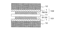
- FIG. 2 is a cross-sectional view showing an outline of a method for producing an electrolyte membrane with a catalyst layer according to this embodiment.
- the catalyst transfer film 10 obtained as described above is laminated on both surfaces of the solid polymer electrolyte membrane 11, and then hot pressing is performed by the hot platen 12 for pressing.
- the catalyst transfer film laminated on one surface of the solid polymer electrolyte membrane 11 constitutes the anode catalyst transfer film 101, and the catalyst layer constitutes the anode catalyst layer 91.
- the catalyst transfer film laminated on the other surface constitutes the cathode catalyst transfer film 102, and the catalyst layer constitutes the cathode catalyst layer 92.
- the manufacturing method of the electrolyte membrane with a catalyst layer according to the present embodiment is configured.
- the configuration of the member during hot pressing is not particularly limited, but the anode catalyst transfer film 101 on which the anode catalyst layer 91 is formed and the cathode catalyst transfer film 102 on which the cathode catalyst layer 92 is formed are solid polymer electrolytes. Desirably, the anode catalyst layer 91 and the cathode catalyst layer 92 are transferred to the solid polymer electrolyte membrane 11 at the same time so as to face both surfaces of the membrane 11. Further, when a buffer material is inserted in order to make the force applied at the time of hot pressing uniform between the laminate of the catalyst transfer film 10 and the solid polymer electrolyte membrane 11 at the time of hot pressing and the hot platen 12 for pressing, A high quality electrolyte membrane with a catalyst layer can be obtained.
- an area having affinity with the catalyst ink and an area having no affinity are formed on the base film, and the catalyst ink is dropped on the area having this affinity. Since the catalyst layer is formed using only the dropped catalyst ink and there is no ink to be discarded, the catalyst layer-attached electrolyte membrane can be manufactured at low cost without loss of the catalyst ink.
- a reusable photomask is used to form a catalyst layer having a desired pattern.
- the catalyst transfer film can be produced with only the base film used in the above.
- an excessive force is applied to the peripheral portion of the catalyst layer formation site during hot pressing during the catalyst layer transfer. This can prevent the damage to the electrolyte membrane and the transfer failure when the press pressure is weakened.
- FIG. 3 is a top view or a bottom view of the main surface of the electrolyte membrane with a catalyst layer as viewed from the front in order to describe the electrolyte membrane with a catalyst layer according to an embodiment of the present invention.
- an anode catalyst layer 91 or a cathode catalyst layer 92 is formed on one surface of the solid polymer electrolyte membrane 11.
- the peripheral portion 93 of the anode catalyst layer 91 or the cathode catalyst layer 92 formed by the method for manufacturing an electrolyte membrane with a catalyst layer according to the present embodiment is accurately obtained by using the photomask for the anode catalyst layer 91 or the cathode catalyst layer 92. Since it is patterned, it has a well-defined shape as compared with the peripheral portion of the catalyst layer formed by the conventional method.
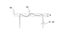
- FIG. 4 is a partially enlarged view of FIG. 3 for explaining the peripheral portion 93 of the catalyst layer-attached electrolyte membrane according to the embodiment of the present invention.
- the outward protrusion of one end of the catalyst layer is the outermost position and the outward protrusion.
- the distance h from the innermost position is formed to be 2.0 ⁇ m or less.
- An ideal outer peripheral line of the catalyst layer is set as a reference line 94 between the outermost position and the innermost position of the peripheral edge portion 93.
- the summit where the length from the reference line 94 to the outside of the catalyst layer 92 is the maximum is the outermost position of the peripheral edge portion 93 indicated by the upper broken line in FIG.
- the valley bottom where the length from the reference line 94 to the inside of the catalyst layer 92 is the maximum is the innermost position of the peripheral edge portion 93 indicated by the lower broken line in FIG. That is, the difference between the maximum peak and the maximum valley bottom corresponds to the distance h between the outermost position and the innermost position.
- the distance h is 2.0 ⁇ m or less, when the gasket for sealing the fuel gas is bonded on the electrolyte membrane around the catalyst layer of the electrolyte membrane with the catalyst layer, the peripheral portion of the catalyst layer and the gasket Positioning with the end portion is facilitated, and reduction of the area of the catalyst layer and exposure of the electrolyte membrane due to the overlap of the catalyst layer and the gasket can be suppressed.
- the difference between the maximum peak and the maximum valley bottom when the peripheral edge is viewed from the upper surface is larger than 2.0 ⁇ m.
- an exposed portion of the electrolyte membrane larger than at least 2.0 ⁇ m is formed between the periphery of the catalyst layer and the end of the gasket, and the catalyst layer and the gasket The gap between cannot be suppressed.
- the method for measuring the difference between the maximum peak and the maximum valley bottom is not particularly limited, but can be calculated by recognizing the edge of the catalyst layer with a camera or the like and measuring it.
- the peripheral edge portion (for example, one side of the catalyst layer) of the anode catalyst layer 91 or the cathode catalyst layer 92 is observed, the interval between the set reference line 94 and the outermost position, The distance between the innermost position is measured and the two distances from the reference line 94 are added to measure the distance h, which is the difference between the maximum peak and the maximum valley bottom.
- Example mentioned later is one Example of this invention, and this invention is not limited only to this Example.
- PET film A polyethylene terephthalate film (hereinafter referred to as PET film) was irradiated with vacuum ultraviolet light having a wavelength of 172 nm to form hydroxyl groups on the surface of the PET film.
- fluoromethoxysilane (trade name: KBM-7103, manufactured by Shin-Etsu Chemical Co., Ltd.), which is a fluoroalkyl silane coupling agent, so that the hydroxyl group on the PET film reacts with the hydrolyzed silane coupling agent.
- a hydroxyl group-formed PET film were heated to 160 ° C., and a silane coupling agent was formed on the PET film by a chemical vapor deposition method (CVD method).
- a silane coupling agent is irradiated with vacuum ultraviolet light having a wavelength of 172 nm through a photomask having a 50 mm square opening and a predetermined pattern processed on the surface, to form a silane coupling agent.
- Two areas were formed, a hydrophilic area where the agent was decomposed and having affinity with the catalyst ink, and a water repellent area where the silane coupling agent remained and had no affinity with the catalyst ink.
- Catalyst layer formation process A platinum-supported carbon catalyst (trade name: TEC10E50E, manufactured by Tanaka Kikinzoku Kogyo Co., Ltd.) having a platinum support amount of 50%, Nafion (registered trademark, manufactured by DuPont), which is a 20% by mass polymer electrolyte solution, and water as a solvent, Mixed. Subsequently, a dispersion treatment was performed with a planetary ball mill to prepare a catalyst ink. The prepared catalyst ink was dropped on a hydrophilic area having affinity with the catalyst ink on the patterned PET film to form a coating film, and then the coating film was dried to form a catalyst layer. At this time, the platinum loading was adjusted so that the cathode catalyst layer was about 0.5 mg / cm 2 and the anode catalyst layer was about 0.3 mg / cm 2 .
- the PET film on which the catalyst layer is formed is irradiated with vacuum ultraviolet light having a wavelength of 172 nm to decompose and remove the water-repellent area silane coupling agent formed on the periphery of the catalyst layer and having no affinity with the catalyst ink.
- a catalyst transfer film was obtained.
- two catalyst transfer films were placed on both sides of the electrolyte membrane so that both catalyst layers faced each other.
- Nafion 211 manufactured by DuPont
- hot pressing was performed under conditions of 130 ° C. and 6 MPa, and only the PET film was peeled off to obtain an electrolyte membrane with a catalyst layer.
- the catalyst transfer film according to this example it was possible to produce an electrolyte membrane with a catalyst layer in which the auxiliary material was suppressed only to the base film of the catalyst transfer film without loss of catalyst ink.
- the catalyst layer of the produced electrolyte membrane with a catalyst layer was observed, no transfer failure was observed.
- the cross-section observation of the produced electrolyte membrane with a catalyst layer was performed, the electrolyte membrane of a catalyst layer formation site
- the present invention can be suitably used for a polymer electrolyte fuel cell, particularly a polymer electrolyte fuel cell single cell or stack in a fuel cell automobile, a household fuel cell, and the like.
Landscapes
- Chemical & Material Sciences (AREA)
- Electrochemistry (AREA)
- General Chemical & Material Sciences (AREA)
- Engineering & Computer Science (AREA)
- Chemical Kinetics & Catalysis (AREA)
- Manufacturing & Machinery (AREA)
- Life Sciences & Earth Sciences (AREA)
- Sustainable Development (AREA)
- Sustainable Energy (AREA)
- Composite Materials (AREA)
- Materials Engineering (AREA)
- Crystallography & Structural Chemistry (AREA)
- Inert Electrodes (AREA)
- Fuel Cell (AREA)
- Laminated Bodies (AREA)
Abstract
Priority Applications (5)
| Application Number | Priority Date | Filing Date | Title |
|---|---|---|---|
| EP14767333.9A EP2978053A4 (fr) | 2013-03-22 | 2014-03-12 | Film de substrat pour film de transfert de catalyseur et son procédé de production, procédé de production de film de transfert de catalyseur, et membrane d'électrolyte dotée d'une couche de catalyseur |
| CN201480016584.XA CN105247722A (zh) | 2013-03-22 | 2014-03-12 | 催化剂转印膜用基材膜和其制造方法、催化剂转印膜的制造方法、带催化剂层电解质膜 |
| JP2015506596A JP6439678B2 (ja) | 2013-03-22 | 2014-03-12 | 触媒転写フィルム用基材フィルム及びその製造方法、触媒転写フィルムの製造方法、触媒層付電解質膜の製造方法 |
| KR1020157030115A KR20150135384A (ko) | 2013-03-22 | 2014-03-12 | 촉매 전사 필름용 기재 필름 및 그 제조 방법, 촉매 전사 필름의 제조 방법, 촉매층을 구비한 전해질막 |
| US14/860,163 US20160013496A1 (en) | 2013-03-22 | 2015-09-21 | Substrate film for use in catalyst transfer film and method for producing the same, method for producing catalyst transfer film, and catalyst coated membrane |
Applications Claiming Priority (2)
| Application Number | Priority Date | Filing Date | Title |
|---|---|---|---|
| JP2013060350 | 2013-03-22 | ||
| JP2013-060350 | 2013-03-22 |
Related Child Applications (1)
| Application Number | Title | Priority Date | Filing Date |
|---|---|---|---|
| US14/860,163 Continuation US20160013496A1 (en) | 2013-03-22 | 2015-09-21 | Substrate film for use in catalyst transfer film and method for producing the same, method for producing catalyst transfer film, and catalyst coated membrane |
Publications (1)
| Publication Number | Publication Date |
|---|---|
| WO2014148011A1 true WO2014148011A1 (fr) | 2014-09-25 |
Family
ID=51579709
Family Applications (1)
| Application Number | Title | Priority Date | Filing Date |
|---|---|---|---|
| PCT/JP2014/001411 Ceased WO2014148011A1 (fr) | 2013-03-22 | 2014-03-12 | Film de substrat pour film de transfert de catalyseur et son procédé de production, procédé de production de film de transfert de catalyseur, et membrane d'électrolyte dotée d'une couche de catalyseur |
Country Status (7)
| Country | Link |
|---|---|
| US (1) | US20160013496A1 (fr) |
| EP (1) | EP2978053A4 (fr) |
| JP (1) | JP6439678B2 (fr) |
| KR (1) | KR20150135384A (fr) |
| CN (1) | CN105247722A (fr) |
| TW (1) | TW201448341A (fr) |
| WO (1) | WO2014148011A1 (fr) |
Cited By (1)
| Publication number | Priority date | Publication date | Assignee | Title |
|---|---|---|---|---|
| CN114424155A (zh) * | 2019-09-23 | 2022-04-29 | 卡纳图有限公司 | 用于压力处理的分层器件和方法 |
Families Citing this family (4)
| Publication number | Priority date | Publication date | Assignee | Title |
|---|---|---|---|---|
| CN110444791A (zh) * | 2019-08-28 | 2019-11-12 | 深圳市通用氢能科技有限公司 | 催化剂涂覆膜、燃料电池及制备方法 |
| JP7359125B2 (ja) * | 2020-10-14 | 2023-10-11 | トヨタ自動車株式会社 | 転写基材再生装置及び転写基材再生方法 |
| CN114725458A (zh) * | 2022-04-11 | 2022-07-08 | 青岛创启信德新能源科技有限公司 | 一种催化剂涂层不易开裂的ccm的制备方法 |
| CN118117098B (zh) * | 2024-04-28 | 2024-09-27 | 上海清能合睿兹新能源科技有限公司 | 转印催化层及其制备方法和转印方法 |
Citations (9)
| Publication number | Priority date | Publication date | Assignee | Title |
|---|---|---|---|---|
| JPH1096810A (ja) * | 1996-09-25 | 1998-04-14 | Sharp Corp | カラーフィルターの製造方法 |
| JP2002169303A (ja) * | 2000-09-19 | 2002-06-14 | Toto Ltd | パターン形成方法、および、このパターン形成方法により製造された電子デバイス、光学素子、光触媒性部材 |
| JP2006286430A (ja) * | 2005-04-01 | 2006-10-19 | Dainippon Printing Co Ltd | 固体高分子形燃料電池用ガスケット付き電解質膜−電極接合体及びその製造方法 |
| JP2008077986A (ja) | 2006-09-21 | 2008-04-03 | Dainippon Printing Co Ltd | 固体高分子形燃料電池用触媒層の転写方法及び電解質膜−触媒層接合体 |
| JP2008077984A (ja) | 2006-09-21 | 2008-04-03 | Dainippon Printing Co Ltd | 固体高分子形燃料電池用触媒層の転写方法及び転写用マスクフィルム |
| JP2008078310A (ja) * | 2006-09-20 | 2008-04-03 | Toppan Printing Co Ltd | 導電性パターンの形成方法、配線板の製造方法及び配線板 |
| JP2010086786A (ja) * | 2008-09-30 | 2010-04-15 | Dainippon Printing Co Ltd | 転写箔フィルム及びそれを用いて得られるマスク付き固体高分子電解質膜、マスク付き触媒転写フィルム、触媒層−電解質膜積層体、固体高分子形燃料電池 |
| JP2011071000A (ja) * | 2009-09-28 | 2011-04-07 | Toppan Printing Co Ltd | 燃料電池用触媒インクの保存方法および使用方法、ならびにこの保存方法により保存される固形触媒インク |
| JP2011216647A (ja) * | 2010-03-31 | 2011-10-27 | Dainippon Printing Co Ltd | パターン形成体の製造方法、機能性素子の製造方法および半導体素子の製造方法 |
Family Cites Families (10)
| Publication number | Priority date | Publication date | Assignee | Title |
|---|---|---|---|---|
| US5631099A (en) * | 1995-09-21 | 1997-05-20 | Hockaday; Robert G. | Surface replica fuel cell |
| US20030013602A1 (en) * | 2000-07-06 | 2003-01-16 | Makoto Uchida | Method for producing an electrolyte film-electrode joint |
| JP2004111818A (ja) * | 2002-09-20 | 2004-04-08 | Seiko Epson Corp | パターン形成方法 |
| JP2005331564A (ja) * | 2004-05-18 | 2005-12-02 | Seiko Epson Corp | 薄膜パターンの形成方法及びデバイス |
| JP2006268430A (ja) * | 2005-03-24 | 2006-10-05 | Hitachi Omron Terminal Solutions Corp | 発券装置 |
| JP2007123043A (ja) * | 2005-10-27 | 2007-05-17 | Canon Inc | 固体高分子型燃料電池の触媒層、その製造方法および固体高分子型燃料電池 |
| KR100659132B1 (ko) * | 2006-02-07 | 2006-12-19 | 삼성에스디아이 주식회사 | 연료전지용 막전극 접합체, 그 제조방법 및 이를 채용한연료전지 |
| WO2009085358A2 (fr) * | 2007-10-05 | 2009-07-09 | Honda Motor Co., Ltd. | Piles à combustible pourvue d'électrodes en pt et alliage de pt déposé par pulvérisation |
| JP5686988B2 (ja) * | 2009-05-04 | 2015-03-18 | シャープ株式会社 | 燃料電池用膜電極複合体に用いられる触媒層、それを用いる燃料電池用膜電極複合体、燃料電池、およびその製造方法 |
| CN103582562B (zh) * | 2011-04-11 | 2015-10-14 | 大日本印刷株式会社 | 聚合物电解质燃料电池用增强材料及其中所使用的粘着粘接组合物 |
-
2014
- 2014-03-12 CN CN201480016584.XA patent/CN105247722A/zh active Pending
- 2014-03-12 KR KR1020157030115A patent/KR20150135384A/ko not_active Withdrawn
- 2014-03-12 WO PCT/JP2014/001411 patent/WO2014148011A1/fr not_active Ceased
- 2014-03-12 JP JP2015506596A patent/JP6439678B2/ja not_active Expired - Fee Related
- 2014-03-12 EP EP14767333.9A patent/EP2978053A4/fr not_active Withdrawn
- 2014-03-17 TW TW103109846A patent/TW201448341A/zh unknown
-
2015
- 2015-09-21 US US14/860,163 patent/US20160013496A1/en not_active Abandoned
Patent Citations (9)
| Publication number | Priority date | Publication date | Assignee | Title |
|---|---|---|---|---|
| JPH1096810A (ja) * | 1996-09-25 | 1998-04-14 | Sharp Corp | カラーフィルターの製造方法 |
| JP2002169303A (ja) * | 2000-09-19 | 2002-06-14 | Toto Ltd | パターン形成方法、および、このパターン形成方法により製造された電子デバイス、光学素子、光触媒性部材 |
| JP2006286430A (ja) * | 2005-04-01 | 2006-10-19 | Dainippon Printing Co Ltd | 固体高分子形燃料電池用ガスケット付き電解質膜−電極接合体及びその製造方法 |
| JP2008078310A (ja) * | 2006-09-20 | 2008-04-03 | Toppan Printing Co Ltd | 導電性パターンの形成方法、配線板の製造方法及び配線板 |
| JP2008077986A (ja) | 2006-09-21 | 2008-04-03 | Dainippon Printing Co Ltd | 固体高分子形燃料電池用触媒層の転写方法及び電解質膜−触媒層接合体 |
| JP2008077984A (ja) | 2006-09-21 | 2008-04-03 | Dainippon Printing Co Ltd | 固体高分子形燃料電池用触媒層の転写方法及び転写用マスクフィルム |
| JP2010086786A (ja) * | 2008-09-30 | 2010-04-15 | Dainippon Printing Co Ltd | 転写箔フィルム及びそれを用いて得られるマスク付き固体高分子電解質膜、マスク付き触媒転写フィルム、触媒層−電解質膜積層体、固体高分子形燃料電池 |
| JP2011071000A (ja) * | 2009-09-28 | 2011-04-07 | Toppan Printing Co Ltd | 燃料電池用触媒インクの保存方法および使用方法、ならびにこの保存方法により保存される固形触媒インク |
| JP2011216647A (ja) * | 2010-03-31 | 2011-10-27 | Dainippon Printing Co Ltd | パターン形成体の製造方法、機能性素子の製造方法および半導体素子の製造方法 |
Non-Patent Citations (1)
| Title |
|---|
| See also references of EP2978053A4 |
Cited By (1)
| Publication number | Priority date | Publication date | Assignee | Title |
|---|---|---|---|---|
| CN114424155A (zh) * | 2019-09-23 | 2022-04-29 | 卡纳图有限公司 | 用于压力处理的分层器件和方法 |
Also Published As
| Publication number | Publication date |
|---|---|
| JPWO2014148011A1 (ja) | 2017-02-16 |
| US20160013496A1 (en) | 2016-01-14 |
| KR20150135384A (ko) | 2015-12-02 |
| JP6439678B2 (ja) | 2018-12-19 |
| CN105247722A (zh) | 2016-01-13 |
| EP2978053A4 (fr) | 2016-09-07 |
| TW201448341A (zh) | 2014-12-16 |
| EP2978053A1 (fr) | 2016-01-27 |
Similar Documents
| Publication | Publication Date | Title |
|---|---|---|
| JP5772813B2 (ja) | 燃料電池膜電極接合体の製造方法および燃料電池膜電極接合体の製造装置 | |
| JP6439678B2 (ja) | 触媒転写フィルム用基材フィルム及びその製造方法、触媒転写フィルムの製造方法、触媒層付電解質膜の製造方法 | |
| CN101853944A (zh) | 复合膜、燃料电池及复合膜的制作方法 | |
| JP5928030B2 (ja) | 固体高分子形燃料電池用膜電極接合体の製造装置 | |
| JP5594021B2 (ja) | 膜電極接合体及びその製造方法 | |
| JPWO2012081169A1 (ja) | 膜−触媒層接合体の製造方法 | |
| JP5286887B2 (ja) | 固体高分子型燃料電池用補強シート付き膜・電極接合体およびその製造方法 | |
| JP5849418B2 (ja) | 膜電極接合体の製造方法 | |
| JP5838570B2 (ja) | 固体高分子形燃料電池における膜電極接合体 | |
| JP5707825B2 (ja) | 固体高分子形燃料電池の膜電極接合体およびその製造方法 | |
| CN101213701A (zh) | 用于燃料电池的亲水导电流体分配板 | |
| JP2006244930A (ja) | 固体高分子形燃料電池用電解質膜−触媒層接合体の製造方法および製造装置 | |
| JP5870643B2 (ja) | 固体高分子形燃料電池用膜電極接合体の製造方法 | |
| JP6364855B2 (ja) | 膜電極接合体の製造方法 | |
| JP6307960B2 (ja) | 固体高分子形燃料電池用触媒層付電解質膜の製造方法、固体高分子形燃料電池および触媒層付電解質膜 | |
| JP6144657B2 (ja) | 燃料電池 | |
| JP6048015B2 (ja) | 膜電極接合体の製造方法 | |
| JP2015069755A (ja) | 膜電極接合体の製造方法 | |
| JP6074979B2 (ja) | 燃料電池用膜電極接合体の製造方法 | |
| JP6319940B2 (ja) | 触媒層付電解質膜の製造方法 | |
| JP5439947B2 (ja) | 膜電極接合体、膜電極接合体製造用の転写基材、膜電極接合体製造用の電極触媒層の塗工転写基材及び固体高分子形燃料電池 | |
| US20260038848A1 (en) | Methods of Coating Plates, Plates, and Fuel Cells | |
| WO2014091870A1 (fr) | Feuille d'électrode de pile à combustible et procédé de fabrication de celle-ci | |
| JP2009245932A (ja) | 燃料電池用電極触媒インク、電極触媒層、膜電極接合体および固体高分子型燃料電池 | |
| JP2018037367A (ja) | 膜電極接合体及びその製造方法、並びに固体高分子形燃料電池 |
Legal Events
| Date | Code | Title | Description |
|---|---|---|---|
| 121 | Ep: the epo has been informed by wipo that ep was designated in this application |
Ref document number: 14767333 Country of ref document: EP Kind code of ref document: A1 |
|
| WWE | Wipo information: entry into national phase |
Ref document number: 2014767333 Country of ref document: EP |
|
| ENP | Entry into the national phase |
Ref document number: 2015506596 Country of ref document: JP Kind code of ref document: A |
|
| NENP | Non-entry into the national phase |
Ref country code: DE |
|
| ENP | Entry into the national phase |
Ref document number: 20157030115 Country of ref document: KR Kind code of ref document: A |