WO2014148531A1 - Fusible - Google Patents
Fusible Download PDFInfo
- Publication number
- WO2014148531A1 WO2014148531A1 PCT/JP2014/057475 JP2014057475W WO2014148531A1 WO 2014148531 A1 WO2014148531 A1 WO 2014148531A1 JP 2014057475 W JP2014057475 W JP 2014057475W WO 2014148531 A1 WO2014148531 A1 WO 2014148531A1
- Authority
- WO
- WIPO (PCT)
- Prior art keywords
- fuse
- rotor
- bus bar
- shaft
- fusible body
- Prior art date
- Legal status (The legal status is an assumption and is not a legal conclusion. Google has not performed a legal analysis and makes no representation as to the accuracy of the status listed.)
- Ceased
Links
Images


Classifications
-
- H—ELECTRICITY
- H01—ELECTRIC ELEMENTS
- H01H—ELECTRIC SWITCHES; RELAYS; SELECTORS; EMERGENCY PROTECTIVE DEVICES
- H01H85/00—Protective devices in which the current flows through a part of fusible material and this current is interrupted by displacement of the fusible material when this current becomes excessive
- H01H85/0039—Means for influencing the rupture process of the fusible element
-
- H—ELECTRICITY
- H01—ELECTRIC ELEMENTS
- H01H—ELECTRIC SWITCHES; RELAYS; SELECTORS; EMERGENCY PROTECTIVE DEVICES
- H01H85/00—Protective devices in which the current flows through a part of fusible material and this current is interrupted by displacement of the fusible material when this current becomes excessive
- H01H85/02—Details
-
- H—ELECTRICITY
- H01—ELECTRIC ELEMENTS
- H01H—ELECTRIC SWITCHES; RELAYS; SELECTORS; EMERGENCY PROTECTIVE DEVICES
- H01H85/00—Protective devices in which the current flows through a part of fusible material and this current is interrupted by displacement of the fusible material when this current becomes excessive
- H01H85/02—Details
- H01H85/04—Fuses, i.e. expendable parts of the protective device, e.g. cartridges
- H01H85/05—Component parts thereof
- H01H85/055—Fusible members
- H01H85/08—Fusible members characterised by the shape or form of the fusible member
-
- H—ELECTRICITY
- H01—ELECTRIC ELEMENTS
- H01H—ELECTRIC SWITCHES; RELAYS; SELECTORS; EMERGENCY PROTECTIVE DEVICES
- H01H2205/00—Movable contacts
- H01H2205/002—Movable contacts fixed to operating part
-
- H—ELECTRICITY
- H01—ELECTRIC ELEMENTS
- H01H—ELECTRIC SWITCHES; RELAYS; SELECTORS; EMERGENCY PROTECTIVE DEVICES
- H01H2235/00—Springs
- H01H2235/01—Spiral spring
Definitions
- the present invention relates to a fuse, and more particularly to a fuse mounted on a vehicle.
- a vehicle such as an automobile is supplied with power from a battery, and a card-ridge type fuse is provided to protect the power from short circuits of various electronic devices and wiring. There is something.
- the fuse 100 includes a fuse body 110 in which a pair of electrical connection portions 112 are provided on both sides of a fusible body 111, an insulating case 120 that houses the fuse body 110, and an upper opening of the case 120.
- a transparent cover 130 to be attached to 121 and a spacer 140 that closes a lower opening (not shown) of the case 120 are configured.
- an object of the present invention is to provide a fuse capable of reducing the manufacturing cost without changing the shape of the fusible body even when the fuse capacity (rating) is changed.
- a first aspect of the present invention is a fuse, comprising a conductive fuse body, a case for housing the fuse body, and a shaft rotatably supported in the case, wherein the fuse bodies are mutually connected.
- a first conductive member and the second conductive member disposed at a spaced position; a fusible body disposed on a circumference having one end connected to the first conductive member and having a rotation center of the shaft as a fulcrum; And a rotor provided with a movable contact that electrically connects the second conductive member and the fusible body and slides on the fusible body in conjunction with the rotation of the shaft.
- the fusible body may have a rotation restricting portion that restricts a rotation range of the rotor.
- An operation unit for rotating the shaft may be provided outside the case.
- An insulating spacer may be interposed between the first conductive member and the rotor, and a spring member may be disposed that biases the second conductive member and the rotor in close contact with each other.
- the fuse capacity (rating) can be changed. As described above, even when the fuse capacity is changed, the manufacturing cost can be reduced without changing the shape of the fusible body.
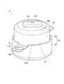
- FIG. 1 is an assembled perspective view showing a fuse according to an embodiment of the present invention.
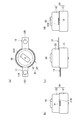
- 2 (a) to 2 (d) are assembled side views showing a fuse according to an embodiment of the present invention.
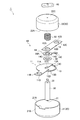
- FIG. 3 is an exploded perspective view showing a fuse according to an embodiment of the present invention.
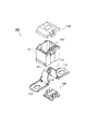
- FIG. 4 is an exploded perspective view showing the first bus bar, the second bus bar, and the rotor according to the embodiment of the present invention.
- FIG. 5A and FIG. 5B are perspective views showing a high rated position and a low rated position of the rotor with respect to the first bus bar and the second bus bar according to an embodiment of the present invention.
- FIG. 6 is a circuit diagram of a fusible body according to an embodiment of the present invention.
- FIG. 7 is a graph showing the resistance value of the current with respect to the angle of the rotor according to the embodiment of the present invention.
- FIG. 8 is an exploded perspective view showing a fuse according to an example of the background art.
- FIG. 1 is an assembled perspective view showing a fuse 1 according to the present embodiment.
- 2 (a) to 2 (d) are assembled four-side views showing the fuse 1 according to the present embodiment.
- 3 and 4 are exploded perspective views showing the fuse 1 according to the present embodiment.
- the fuse 1 includes a conductive fuse body 10 connected to an electrical connection portion (not shown) of a power source such as a battery, a case 20 that houses the fuse body 10, and a case 20. And a shaft 30 rotatably supported therein.
- the fuse body 10 interrupts energization to various electronic devices from a power source such as a battery.
- the fuse body 10 includes a first bus bar 11 as a first conductive member and a second bus bar 12 as a second conductive member, a fusible body 13 capable of interrupting energization, A rotor 14 that electrically connects the fusible body 13 is provided.
- the first bus bar 11 is a portion that is connected to an electrical connection portion (not shown) and receives an electric current, and is formed of a plate-like conductive member (for example, metal).
- An insulating spacer 40 is interposed between the first bus bar 11 and the rotor 14.
- the first bus bar 11 includes an internal region 11A disposed in the case 20 and an external connection portion 11B disposed outside the case 20.
- the internal region 11A is formed in a substantially semicircular shape in plan view.
- a shaft insertion portion 11C into which the shaft 30 is inserted is formed in the internal region 11A.
- the external connection portion 11B is continuous with the internal region 11A and is formed in a substantially rectangular shape in plan view.
- the external connection portion 11B is formed with an attachment hole 11D into which fastening means (not shown) such as a bolt for attaching to the electrical connection portion (not shown) is inserted.
- the second bus bar 12 is a portion that is connected to an electrical connection portion (not shown) and outputs a current, and is formed of a plate-like conductive member (for example, metal).
- a spring 50 is disposed as a spring member that urges the second bus bar 12 and the rotor 14 to come into close contact with each other.
- the second bus bar 12 is formed in a substantially rectangular shape in plan view.
- the second bus bar 12 is formed with a shaft insertion hole 12A into which the shaft 30 is inserted, and an attachment hole 12B into which fastening means (not shown) such as a bolt for attaching to the electrical connection part (not shown) is inserted. Yes.
- the fusible body 13 is provided integrally with the first bus bar 11.
- the fusible body 13 is disposed along a circumference with the rotation center of the shaft 30 as a fulcrum. That is, the fusible body 13 is formed in an arc around the shaft 30.
- One end 13 ⁇ / b> A of the fusible body 13 is connected to the inner region 11 ⁇ / b> A of the first bus bar 11.
- the other end 13 ⁇ / b> B of the fusible body 13 is slightly separated from the inner region 11 ⁇ / b> A of the first bus bar 11.
- Stoppers 13C and 13D as rotation restricting portions for restricting the rotation range of the rotor 14 are provided on both one end 13A and the other end 13B of these fusible bodies 13, respectively.
- the rotor 14 is formed of a plate-like conductive member (for example, metal).
- the rotor 14 is disposed between the spacer 40 and the second bus bar 12, and electrically connects the second bus bar 12 and the fusible body 13.
- the rotor 14 has a high rated position where the fusible body 13 interrupts the high rated current (see FIG. 5A) and a low rated position where the fusible body 13 interrupts the low rated current (see FIG. 5B).
- fuse capacity The capacity of the current that is cut off by the fusible body 13
- the rotor 14 includes a frame body 14A that rotates around the shaft 30 and a movable piece 14B that protrudes from the frame body 14A.
- the frame body 14A is formed with a shaft insertion hole 14C into which the shaft 30 is inserted.
- a fixing portion 14D that protrudes toward the shaft 30 and is fixed to a hole (not shown) of the shaft 30 is provided at the periphery of the shaft insertion hole 14C.
- a movable contact 14E that protrudes toward the fusible body 13 and slides on the fusible body 13 is formed at the tip of the movable piece 14B.
- the case 20 has a cylindrical shape and is formed of a synthetic resin having an insulating property.
- the case 20 includes an undercase 21 and an upper case 22 that is attached to the upper opening 21 ⁇ / b> A of the undercase 21.
- a shaft 30 is provided along the case axial direction.
- a lower end 31 of the shaft 30 is supported by the undercase 21, and an upper end 32 of the shaft 30 penetrates the upper case 22.
- a cutout portion 21B in which the first bus bar 11 is disposed is formed in the upper opening 21A of the undercase 21, a cutout portion 21B in which the first bus bar 11 is disposed is formed.
- the lower opening 22A of the upper case 22 is formed with a notch 22B in which the second bus bar 12 is disposed.
- an operation unit 60 for operating the rotation of the rotor 14 from the outside of the case 20 via the shaft 30 is provided.
- the upper end 32 (head) of the shaft 30 penetrating the upper case 22 is fixed to the operation unit 60.
- the operation unit 60 When the operation unit 60 is rotated by an operator, the shaft 30 rotates, and the rotor 14 fixed to the shaft 30 rotates.
- FIG. 5A is a perspective view showing a high rated position of the rotor 14 with respect to the first bus bar 11 and the second bus bar 12
- FIG. 5B is a rotor with respect to the first bus bar 11 and the second bus bar 12.
- 14 is a perspective view showing 14 high rated positions.
- FIG. 6 is a circuit diagram of the fusible body 13.
- FIG. 7 is a graph showing the resistance value of the current with respect to the angle of the rotor 14.
- the movable contact 14E of the movable piece 14B is positioned on the one end 13A side of the fusible body 13, so that the movable piece 14B is moved from the one end 13A of the fusible body 13. It is comprised so that the distance to may become short. Thereby, the resistance value of the current flowing through the fusible body 13 is reduced, and the current exceeding the high rating for energizing the fusible body 13 can be cut off.
- the movable contact 14E of the movable piece 14B is located on the other end 13B side of the fusible body 13, so that the movable piece is moved from one end 13A of the fusible body 13.
- the distance up to 14B is configured to be long. Thereby, the resistance value of the current flowing through the fusible body 13 is increased, and a current of a low rating or higher that energizes the fusible body 13 can be cut off.
- the substantial resistance of the fusible body 13 changes. That is, by changing the resistance value of the current flowing through the fusible body 13 from the first bus bar 11 (mounting hole 11D) on the current input side to the second bus bar 12 (mounting hole 12B) on the current output side, the fuse The capacity (rating) can be changed.
- the resistance value of the current flowing through the fusible body 13 is about 0.300 milliohms, corresponding to 140 amp battery.
- the current resistance values for other rotor angles are as shown in FIG. As shown in FIG. 7, by changing the rotor angle, the current resistance value changes and the fuse capacity can be changed, so that it is possible to deal with batteries having various capacities.
- stoppers 13C and 13D are respectively provided at one end 13A and the other end 13B of the fusible body 13. Thereby, since the movable contact 14E contacts the stoppers 13C and 13D, the rotation range of the rotor 14 can be restricted.
- the operation unit 60 is provided outside the case 20. Thereby, the fuse capacity (rating) can be easily changed from the outside of the case 20.
- a spacer 40 is interposed between the first bus bar 11 and the rotor 14. Thereby, the 1st bus bar 11 and the 2nd bus bar 12 can be certainly disconnected.
- a spring 50 is disposed above the second bus bar 12 to bias the second bus bar 12 and the rotor 14 in close contact with each other. Thereby, the vibration etc. which arise between the 1st bus bar 11 and the rotor 14, and between the 2nd bus bar 12 and the rotor 14 can be prevented.
- the fusible body 13 is provided integrally with the first bus bar 11. Thereby, compared with the case where the fusible body 13 is provided separately from the first bus bar 11, it contributes to the reduction of the number of parts.
- a shaft insertion portion 11C is formed in the first bus bar 11
- a shaft insertion hole 12A is formed in the second bus bar 12
- a shaft insertion hole 14C is formed in the rotor 14. That is, a hole into which the shaft 30 is inserted is formed in each member. Thereby, each member can be arrange
- the embodiment of the present invention can be modified as follows. Specifically, the first bus bar 11 has been described as the current input side and the second bus bar 12 has been described as the current output side. However, the present invention is not limited to this, and the first bus bar 11 is the current output side. Yes, the second bus bar 12 may be on the current input side.
- the fusible body 13 has been described as being formed integrally with the first bus bar 11, but is not limited thereto, and may be formed integrally with the second bus bar 12.
- the fusible body 13 is not necessarily formed integrally with the first bus bar 11 or the second bus bar 12, and may be connected to the first bus bar 11 or the second bus bar 12 by welding or the like, for example. Good.
- both the one end 13A and the other end 13B of the fusible body 13 are provided with the stoppers 13C and 13D, respectively, the present invention is not limited to this, and the stoppers 13C and 13D are not provided. Or may be provided on either one of them.
- the stoppers 13C and 13D are not necessarily provided on the fusible body 13, and may be provided, for example, on the inner peripheral surface of the case 20 on the condition that the rotation range of the rotor 14 can be regulated.
- the length of the soluble body 13 changes in response to rotation of the rotor 14, it is not limited to this, for example, the soluble body 13 and the interlock with the rotation of the rotor 14 The contact area with the movable contact 14E may change.
- the operation unit 60 has been described as being provided on the upper surface 22C of the upper case 22, the operation unit 60 is not limited to this, and it is only necessary to be able to rotate the rotor 14 via the shaft 30, for example, the undercase 21 It may be provided on the bottom surface of the case 20 or may be provided on the outer peripheral surface of the case 20.
- an amperage or the like may be displayed on the upper surface 22C of the upper case 22 provided with the operation unit 60 corresponding to the angle of the rotor 14. Further, positioning means (for example, slight unevenness) for positioning the rotor 14 may be provided in the fusible body 13 for each angle of the rotor 14.
Landscapes
- Fuses (AREA)
Abstract
L'invention concerne un fusible (1) qui comprend : un corps de fusible conducteur (10) ; un boîtier (20) destiné à recevoir le corps de fusible (10) ; et un arbre (30) supporté de manière rotative dans le boîtier (20). Le corps de fusible (10) comprend : une première barre omnibus (11) et une seconde barre omnibus (12) disposées dans des positions mutuellement séparées ; un élément fusible (13), dont un côté d'extrémité est relié à la première barre omnibus (11), disposé le long d'une circonférence ayant comme point d'appui le centre de rotation de l'arbre (30) ; et un rotor (14) reliant électriquement la première barre omnibus (11) et la seconde barre omnibus (12), un point de contact mobile (14E) lié à la rotation de l'arbre (30) et coulissant sur l'élément fusible (13) étant situé sur le rotor (14).
Priority Applications (2)
| Application Number | Priority Date | Filing Date | Title |
|---|---|---|---|
| CN201480017302.8A CN105051856A (zh) | 2013-03-21 | 2014-03-19 | 熔断器 |
| US14/851,051 US20150380195A1 (en) | 2013-03-21 | 2015-09-11 | Fuse |
Applications Claiming Priority (2)
| Application Number | Priority Date | Filing Date | Title |
|---|---|---|---|
| JP2013-058078 | 2013-03-21 | ||
| JP2013058078A JP6175256B2 (ja) | 2013-03-21 | 2013-03-21 | ヒューズ |
Related Child Applications (1)
| Application Number | Title | Priority Date | Filing Date |
|---|---|---|---|
| US14/851,051 Continuation US20150380195A1 (en) | 2013-03-21 | 2015-09-11 | Fuse |
Publications (1)
| Publication Number | Publication Date |
|---|---|
| WO2014148531A1 true WO2014148531A1 (fr) | 2014-09-25 |
Family
ID=51580206
Family Applications (1)
| Application Number | Title | Priority Date | Filing Date |
|---|---|---|---|
| PCT/JP2014/057475 Ceased WO2014148531A1 (fr) | 2013-03-21 | 2014-03-19 | Fusible |
Country Status (4)
| Country | Link |
|---|---|
| US (1) | US20150380195A1 (fr) |
| JP (1) | JP6175256B2 (fr) |
| CN (1) | CN105051856A (fr) |
| WO (1) | WO2014148531A1 (fr) |
Families Citing this family (2)
| Publication number | Priority date | Publication date | Assignee | Title |
|---|---|---|---|---|
| US10275626B2 (en) | 2014-02-07 | 2019-04-30 | Sony Interactive Entertainment Inc. | Sheet body, steroscopic object, and information code reading system |
| CN116092895A (zh) * | 2023-03-24 | 2023-05-09 | 欣旺达电动汽车电池有限公司 | 一种熔断器及电池包 |
Citations (2)
| Publication number | Priority date | Publication date | Assignee | Title |
|---|---|---|---|---|
| JPS6268203U (fr) * | 1985-09-30 | 1987-04-28 | ||
| JP2008053163A (ja) * | 2006-08-28 | 2008-03-06 | Yazaki Corp | ヒューズエレメント及びヒューズエレメントの製造方法 |
Family Cites Families (3)
| Publication number | Priority date | Publication date | Assignee | Title |
|---|---|---|---|---|
| JP2715354B2 (ja) * | 1992-03-25 | 1998-02-18 | 矢崎総業株式会社 | ヒュージブルリンク |
| JP3242095B2 (ja) * | 2000-05-16 | 2001-12-25 | 矢崎総業株式会社 | ヒューズ |
| CN101604602B (zh) * | 2008-06-10 | 2012-05-16 | 邱鸿智 | 微型保险丝制造方法及成品 |
-
2013
- 2013-03-21 JP JP2013058078A patent/JP6175256B2/ja not_active Expired - Fee Related
-
2014
- 2014-03-19 WO PCT/JP2014/057475 patent/WO2014148531A1/fr not_active Ceased
- 2014-03-19 CN CN201480017302.8A patent/CN105051856A/zh active Pending
-
2015
- 2015-09-11 US US14/851,051 patent/US20150380195A1/en not_active Abandoned
Patent Citations (2)
| Publication number | Priority date | Publication date | Assignee | Title |
|---|---|---|---|---|
| JPS6268203U (fr) * | 1985-09-30 | 1987-04-28 | ||
| JP2008053163A (ja) * | 2006-08-28 | 2008-03-06 | Yazaki Corp | ヒューズエレメント及びヒューズエレメントの製造方法 |
Also Published As
| Publication number | Publication date |
|---|---|
| JP2014182991A (ja) | 2014-09-29 |
| CN105051856A (zh) | 2015-11-11 |
| JP6175256B2 (ja) | 2017-08-02 |
| US20150380195A1 (en) | 2015-12-31 |
Similar Documents
| Publication | Publication Date | Title |
|---|---|---|
| US9627783B1 (en) | Terminal connection structure | |
| JP2018010768A (ja) | 多連型ヒューズ | |
| CN101409406A (zh) | 连接器的连接结构 | |
| JP2008219983A (ja) | ブラシホルダ | |
| JP5328459B2 (ja) | ヒューズユニット | |
| JP6175256B2 (ja) | ヒューズ | |
| JP6307405B2 (ja) | バッテリ端子 | |
| JP6125334B2 (ja) | 電気接続箱 | |
| JP6309303B2 (ja) | 電気接続箱 | |
| JP5746500B2 (ja) | バスバ及びそれを備えた電気接続箱 | |
| US20150140875A1 (en) | Connection terminal | |
| JP2015076378A (ja) | バッテリ接続用のヒューズユニット | |
| JP2013084453A (ja) | ヒューズセット及び電気接続箱 | |
| JP7077984B2 (ja) | コネクタ装置 | |
| JP5318469B2 (ja) | ヒュージブルリンクユニットの接続構造 | |
| JP2017004874A (ja) | 端子台 | |
| JP2014232642A (ja) | ヒューズユニット | |
| WO2015064245A1 (fr) | Dispositif à fusible | |
| JP5843619B2 (ja) | 電気接続箱 | |
| JP6287128B2 (ja) | 逆流防止装置 | |
| JP2013037877A (ja) | ヒューズ | |
| JP5506858B2 (ja) | 回転電機 | |
| JP3109953U (ja) | ヒューズ機能付きバスバー | |
| JP2008111804A (ja) | トルク検知センサ | |
| JP2014022173A (ja) | ヒューズ |
Legal Events
| Date | Code | Title | Description |
|---|---|---|---|
| WWE | Wipo information: entry into national phase |
Ref document number: 201480017302.8 Country of ref document: CN |
|
| 121 | Ep: the epo has been informed by wipo that ep was designated in this application |
Ref document number: 14771158 Country of ref document: EP Kind code of ref document: A1 |
|
| NENP | Non-entry into the national phase |
Ref country code: DE |
|
| 122 | Ep: pct application non-entry in european phase |
Ref document number: 14771158 Country of ref document: EP Kind code of ref document: A1 |