WO2014148531A1 - ヒューズ - Google Patents
ヒューズ Download PDFInfo
- Publication number
- WO2014148531A1 WO2014148531A1 PCT/JP2014/057475 JP2014057475W WO2014148531A1 WO 2014148531 A1 WO2014148531 A1 WO 2014148531A1 JP 2014057475 W JP2014057475 W JP 2014057475W WO 2014148531 A1 WO2014148531 A1 WO 2014148531A1
- Authority
- WO
- WIPO (PCT)
- Prior art keywords
- fuse
- rotor
- bus bar
- shaft
- fusible body
- Prior art date
- Legal status (The legal status is an assumption and is not a legal conclusion. Google has not performed a legal analysis and makes no representation as to the accuracy of the status listed.)
- Ceased
Links
Images


Classifications
-
- H—ELECTRICITY
- H01—ELECTRIC ELEMENTS
- H01H—ELECTRIC SWITCHES; RELAYS; SELECTORS; EMERGENCY PROTECTIVE DEVICES
- H01H85/00—Protective devices in which the current flows through a part of fusible material and this current is interrupted by displacement of the fusible material when this current becomes excessive
- H01H85/0039—Means for influencing the rupture process of the fusible element
-
- H—ELECTRICITY
- H01—ELECTRIC ELEMENTS
- H01H—ELECTRIC SWITCHES; RELAYS; SELECTORS; EMERGENCY PROTECTIVE DEVICES
- H01H85/00—Protective devices in which the current flows through a part of fusible material and this current is interrupted by displacement of the fusible material when this current becomes excessive
- H01H85/02—Details
-
- H—ELECTRICITY
- H01—ELECTRIC ELEMENTS
- H01H—ELECTRIC SWITCHES; RELAYS; SELECTORS; EMERGENCY PROTECTIVE DEVICES
- H01H85/00—Protective devices in which the current flows through a part of fusible material and this current is interrupted by displacement of the fusible material when this current becomes excessive
- H01H85/02—Details
- H01H85/04—Fuses, i.e. expendable parts of the protective device, e.g. cartridges
- H01H85/05—Component parts thereof
- H01H85/055—Fusible members
- H01H85/08—Fusible members characterised by the shape or form of the fusible member
-
- H—ELECTRICITY
- H01—ELECTRIC ELEMENTS
- H01H—ELECTRIC SWITCHES; RELAYS; SELECTORS; EMERGENCY PROTECTIVE DEVICES
- H01H2205/00—Movable contacts
- H01H2205/002—Movable contacts fixed to operating part
-
- H—ELECTRICITY
- H01—ELECTRIC ELEMENTS
- H01H—ELECTRIC SWITCHES; RELAYS; SELECTORS; EMERGENCY PROTECTIVE DEVICES
- H01H2235/00—Springs
- H01H2235/01—Spiral spring
Definitions
- the present invention relates to a fuse, and more particularly to a fuse mounted on a vehicle.
- a vehicle such as an automobile is supplied with power from a battery, and a card-ridge type fuse is provided to protect the power from short circuits of various electronic devices and wiring. There is something.
- the fuse 100 includes a fuse body 110 in which a pair of electrical connection portions 112 are provided on both sides of a fusible body 111, an insulating case 120 that houses the fuse body 110, and an upper opening of the case 120.
- a transparent cover 130 to be attached to 121 and a spacer 140 that closes a lower opening (not shown) of the case 120 are configured.
- an object of the present invention is to provide a fuse capable of reducing the manufacturing cost without changing the shape of the fusible body even when the fuse capacity (rating) is changed.
- a first aspect of the present invention is a fuse, comprising a conductive fuse body, a case for housing the fuse body, and a shaft rotatably supported in the case, wherein the fuse bodies are mutually connected.
- a first conductive member and the second conductive member disposed at a spaced position; a fusible body disposed on a circumference having one end connected to the first conductive member and having a rotation center of the shaft as a fulcrum; And a rotor provided with a movable contact that electrically connects the second conductive member and the fusible body and slides on the fusible body in conjunction with the rotation of the shaft.
- the fusible body may have a rotation restricting portion that restricts a rotation range of the rotor.
- An operation unit for rotating the shaft may be provided outside the case.
- An insulating spacer may be interposed between the first conductive member and the rotor, and a spring member may be disposed that biases the second conductive member and the rotor in close contact with each other.
- the fuse capacity (rating) can be changed. As described above, even when the fuse capacity is changed, the manufacturing cost can be reduced without changing the shape of the fusible body.
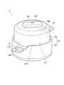
- FIG. 1 is an assembled perspective view showing a fuse according to an embodiment of the present invention.
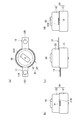
- 2 (a) to 2 (d) are assembled side views showing a fuse according to an embodiment of the present invention.
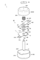
- FIG. 3 is an exploded perspective view showing a fuse according to an embodiment of the present invention.
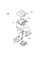
- FIG. 4 is an exploded perspective view showing the first bus bar, the second bus bar, and the rotor according to the embodiment of the present invention.
- FIG. 5A and FIG. 5B are perspective views showing a high rated position and a low rated position of the rotor with respect to the first bus bar and the second bus bar according to an embodiment of the present invention.
- FIG. 6 is a circuit diagram of a fusible body according to an embodiment of the present invention.
- FIG. 7 is a graph showing the resistance value of the current with respect to the angle of the rotor according to the embodiment of the present invention.
- FIG. 8 is an exploded perspective view showing a fuse according to an example of the background art.
- FIG. 1 is an assembled perspective view showing a fuse 1 according to the present embodiment.
- 2 (a) to 2 (d) are assembled four-side views showing the fuse 1 according to the present embodiment.
- 3 and 4 are exploded perspective views showing the fuse 1 according to the present embodiment.
- the fuse 1 includes a conductive fuse body 10 connected to an electrical connection portion (not shown) of a power source such as a battery, a case 20 that houses the fuse body 10, and a case 20. And a shaft 30 rotatably supported therein.
- the fuse body 10 interrupts energization to various electronic devices from a power source such as a battery.
- the fuse body 10 includes a first bus bar 11 as a first conductive member and a second bus bar 12 as a second conductive member, a fusible body 13 capable of interrupting energization, A rotor 14 that electrically connects the fusible body 13 is provided.
- the first bus bar 11 is a portion that is connected to an electrical connection portion (not shown) and receives an electric current, and is formed of a plate-like conductive member (for example, metal).
- An insulating spacer 40 is interposed between the first bus bar 11 and the rotor 14.
- the first bus bar 11 includes an internal region 11A disposed in the case 20 and an external connection portion 11B disposed outside the case 20.
- the internal region 11A is formed in a substantially semicircular shape in plan view.
- a shaft insertion portion 11C into which the shaft 30 is inserted is formed in the internal region 11A.
- the external connection portion 11B is continuous with the internal region 11A and is formed in a substantially rectangular shape in plan view.
- the external connection portion 11B is formed with an attachment hole 11D into which fastening means (not shown) such as a bolt for attaching to the electrical connection portion (not shown) is inserted.
- the second bus bar 12 is a portion that is connected to an electrical connection portion (not shown) and outputs a current, and is formed of a plate-like conductive member (for example, metal).
- a spring 50 is disposed as a spring member that urges the second bus bar 12 and the rotor 14 to come into close contact with each other.
- the second bus bar 12 is formed in a substantially rectangular shape in plan view.
- the second bus bar 12 is formed with a shaft insertion hole 12A into which the shaft 30 is inserted, and an attachment hole 12B into which fastening means (not shown) such as a bolt for attaching to the electrical connection part (not shown) is inserted. Yes.
- the fusible body 13 is provided integrally with the first bus bar 11.
- the fusible body 13 is disposed along a circumference with the rotation center of the shaft 30 as a fulcrum. That is, the fusible body 13 is formed in an arc around the shaft 30.
- One end 13 ⁇ / b> A of the fusible body 13 is connected to the inner region 11 ⁇ / b> A of the first bus bar 11.
- the other end 13 ⁇ / b> B of the fusible body 13 is slightly separated from the inner region 11 ⁇ / b> A of the first bus bar 11.
- Stoppers 13C and 13D as rotation restricting portions for restricting the rotation range of the rotor 14 are provided on both one end 13A and the other end 13B of these fusible bodies 13, respectively.
- the rotor 14 is formed of a plate-like conductive member (for example, metal).
- the rotor 14 is disposed between the spacer 40 and the second bus bar 12, and electrically connects the second bus bar 12 and the fusible body 13.
- the rotor 14 has a high rated position where the fusible body 13 interrupts the high rated current (see FIG. 5A) and a low rated position where the fusible body 13 interrupts the low rated current (see FIG. 5B).
- fuse capacity The capacity of the current that is cut off by the fusible body 13
- the rotor 14 includes a frame body 14A that rotates around the shaft 30 and a movable piece 14B that protrudes from the frame body 14A.
- the frame body 14A is formed with a shaft insertion hole 14C into which the shaft 30 is inserted.
- a fixing portion 14D that protrudes toward the shaft 30 and is fixed to a hole (not shown) of the shaft 30 is provided at the periphery of the shaft insertion hole 14C.
- a movable contact 14E that protrudes toward the fusible body 13 and slides on the fusible body 13 is formed at the tip of the movable piece 14B.
- the case 20 has a cylindrical shape and is formed of a synthetic resin having an insulating property.
- the case 20 includes an undercase 21 and an upper case 22 that is attached to the upper opening 21 ⁇ / b> A of the undercase 21.
- a shaft 30 is provided along the case axial direction.
- a lower end 31 of the shaft 30 is supported by the undercase 21, and an upper end 32 of the shaft 30 penetrates the upper case 22.
- a cutout portion 21B in which the first bus bar 11 is disposed is formed in the upper opening 21A of the undercase 21, a cutout portion 21B in which the first bus bar 11 is disposed is formed.
- the lower opening 22A of the upper case 22 is formed with a notch 22B in which the second bus bar 12 is disposed.
- an operation unit 60 for operating the rotation of the rotor 14 from the outside of the case 20 via the shaft 30 is provided.
- the upper end 32 (head) of the shaft 30 penetrating the upper case 22 is fixed to the operation unit 60.
- the operation unit 60 When the operation unit 60 is rotated by an operator, the shaft 30 rotates, and the rotor 14 fixed to the shaft 30 rotates.
- FIG. 5A is a perspective view showing a high rated position of the rotor 14 with respect to the first bus bar 11 and the second bus bar 12
- FIG. 5B is a rotor with respect to the first bus bar 11 and the second bus bar 12.
- 14 is a perspective view showing 14 high rated positions.
- FIG. 6 is a circuit diagram of the fusible body 13.
- FIG. 7 is a graph showing the resistance value of the current with respect to the angle of the rotor 14.
- the movable contact 14E of the movable piece 14B is positioned on the one end 13A side of the fusible body 13, so that the movable piece 14B is moved from the one end 13A of the fusible body 13. It is comprised so that the distance to may become short. Thereby, the resistance value of the current flowing through the fusible body 13 is reduced, and the current exceeding the high rating for energizing the fusible body 13 can be cut off.
- the movable contact 14E of the movable piece 14B is located on the other end 13B side of the fusible body 13, so that the movable piece is moved from one end 13A of the fusible body 13.
- the distance up to 14B is configured to be long. Thereby, the resistance value of the current flowing through the fusible body 13 is increased, and a current of a low rating or higher that energizes the fusible body 13 can be cut off.
- the substantial resistance of the fusible body 13 changes. That is, by changing the resistance value of the current flowing through the fusible body 13 from the first bus bar 11 (mounting hole 11D) on the current input side to the second bus bar 12 (mounting hole 12B) on the current output side, the fuse The capacity (rating) can be changed.
- the resistance value of the current flowing through the fusible body 13 is about 0.300 milliohms, corresponding to 140 amp battery.
- the current resistance values for other rotor angles are as shown in FIG. As shown in FIG. 7, by changing the rotor angle, the current resistance value changes and the fuse capacity can be changed, so that it is possible to deal with batteries having various capacities.
- stoppers 13C and 13D are respectively provided at one end 13A and the other end 13B of the fusible body 13. Thereby, since the movable contact 14E contacts the stoppers 13C and 13D, the rotation range of the rotor 14 can be restricted.
- the operation unit 60 is provided outside the case 20. Thereby, the fuse capacity (rating) can be easily changed from the outside of the case 20.
- a spacer 40 is interposed between the first bus bar 11 and the rotor 14. Thereby, the 1st bus bar 11 and the 2nd bus bar 12 can be certainly disconnected.
- a spring 50 is disposed above the second bus bar 12 to bias the second bus bar 12 and the rotor 14 in close contact with each other. Thereby, the vibration etc. which arise between the 1st bus bar 11 and the rotor 14, and between the 2nd bus bar 12 and the rotor 14 can be prevented.
- the fusible body 13 is provided integrally with the first bus bar 11. Thereby, compared with the case where the fusible body 13 is provided separately from the first bus bar 11, it contributes to the reduction of the number of parts.
- a shaft insertion portion 11C is formed in the first bus bar 11
- a shaft insertion hole 12A is formed in the second bus bar 12
- a shaft insertion hole 14C is formed in the rotor 14. That is, a hole into which the shaft 30 is inserted is formed in each member. Thereby, each member can be arrange
- the embodiment of the present invention can be modified as follows. Specifically, the first bus bar 11 has been described as the current input side and the second bus bar 12 has been described as the current output side. However, the present invention is not limited to this, and the first bus bar 11 is the current output side. Yes, the second bus bar 12 may be on the current input side.
- the fusible body 13 has been described as being formed integrally with the first bus bar 11, but is not limited thereto, and may be formed integrally with the second bus bar 12.
- the fusible body 13 is not necessarily formed integrally with the first bus bar 11 or the second bus bar 12, and may be connected to the first bus bar 11 or the second bus bar 12 by welding or the like, for example. Good.
- both the one end 13A and the other end 13B of the fusible body 13 are provided with the stoppers 13C and 13D, respectively, the present invention is not limited to this, and the stoppers 13C and 13D are not provided. Or may be provided on either one of them.
- the stoppers 13C and 13D are not necessarily provided on the fusible body 13, and may be provided, for example, on the inner peripheral surface of the case 20 on the condition that the rotation range of the rotor 14 can be regulated.
- the length of the soluble body 13 changes in response to rotation of the rotor 14, it is not limited to this, for example, the soluble body 13 and the interlock with the rotation of the rotor 14 The contact area with the movable contact 14E may change.
- the operation unit 60 has been described as being provided on the upper surface 22C of the upper case 22, the operation unit 60 is not limited to this, and it is only necessary to be able to rotate the rotor 14 via the shaft 30, for example, the undercase 21 It may be provided on the bottom surface of the case 20 or may be provided on the outer peripheral surface of the case 20.
- an amperage or the like may be displayed on the upper surface 22C of the upper case 22 provided with the operation unit 60 corresponding to the angle of the rotor 14. Further, positioning means (for example, slight unevenness) for positioning the rotor 14 may be provided in the fusible body 13 for each angle of the rotor 14.
Landscapes
- Fuses (AREA)
Abstract
ヒューズ(1)は、導電性のヒューズ本体(10)と、ヒューズ本体(10)を収容するケース(20)と、ケース(20)内に回転自在に支持されたシャフト(30)とを備える。ヒューズ本体(10)は、互いに離間位置に配置された第1バスバ(11)及び第2バスバ(12)と、第1バスバ(11)に一端側が接続され、シャフト(30)の回転中心を支点とする円周上に沿って配置された可溶体(13)と、前記第1バスバ(11)及び第2バスバ(12)を電気的に接続し、シャフト(30)の回転に連動して可溶体(13)上を摺動する可動接点(14E)が設けられた回転子(14)とを備える。
Description
本発明は、ヒューズに関し、特に、車両に搭載されるヒューズに関する。
一般的に、自動車等の車両には、バッテリーから電源が供給されるようになっており、各種電子機器や配線などの短絡等から電源を保護するために、カードリッジタイプのヒューズが設けられたものがある。
この種のヒューズの一例について、図8を参照しながら説明する。図8に示すように、ヒューズ100は、可溶体111の両側に一対の電気接続部112が設けられたヒューズ本体110と、ヒューズ本体110を収容する絶縁性のケース120と、ケース120の上側開口121に装着される透明性のカバー130と、ケース120の下側開口(不図示)を塞ぐスペーサ140とによって構成されている。
このようなヒューズ100では、ヒューズ本体110の可溶体111に定格以上の電流が通電されると、可溶部111に設けられた低融点金属111Aが溶融して、溶融した低融点金属111Aが可溶部111に拡散して、可溶部111の融点を低下させる。これにより、可溶部111の発熱が促進され、可溶部111の一部が溶断して通電(電気的接続)が遮断される。
しかしながら、上述した従来のヒューズ100では、ヒューズ容量(定格)を変更する場合、可溶体111の長さや幅、厚みを変更する必要があり、複数のヒューズ容量に対応するヒューズ本体110を用意する必要があった。この複数のヒューズ容量に対応するヒューズ本体110を製造するためには、プレス機における複数の金型等が必要であり、製造コストの増大を招いてしまう。
そこで、本発明は、ヒューズ容量(定格)を変更する場合であっても、可溶体の形状を変更することなく、製造コストを低減できるヒューズの提供を目的とする。
本発明の第1の態様はヒューズであって、導電性のヒューズ本体と、前記ヒューズ本体を収容するケースと、前記ケース内に回転自在に支持されたシャフトとを備え、前記ヒューズ本体は、互いに離間位置に配置された第1導電部材及び前記第2導電部材と、前記第1導電部材に一端側が接続され、前記シャフトの回転中心を支点とする円周上に沿って配置された可溶体と、前記第2導電部材と前記可溶体とを電気的に接続し、前記シャフトの回転に連動して前記可溶体上を摺動する可動接点が設けられた回転子とを備えることを要旨とする。
前記可溶体は、前記回転子の回転範囲を規制する回転規制部を有していてもよい。
前記ケースの外部には、前記シャフトを回転する操作部が設けられていてもよい。
前記第1導電部材と前記回転子との間に絶縁性のスペーサを介在すると共に、前記第2導電部材及び前記回転子との間を密接させる方向に付勢するバネ部材を配置してもよい。
本発明の特徴によれば、回転子の可動接点がシャフトの回転に連動して可溶体上を摺動することで、可溶体の長さが変化するため、ヒューズ容量(定格)を変更できる。以上により、ヒューズ容量を変更する場合であっても、可溶体の形状を変更することなく、製造コストを低減できる。
次に、本発明の一実施形態に係るヒューズについて、図面を参照しながら説明する。なお、以下の図面の記載において、同一または類似の部分には、同一または類似の符号を付している。ただし、図面は模式的なものであり、各寸法の比率などは現実のものとは異なることに留意すべきである。したがって、具体的な寸法などは以下の説明を参酌して判断すべきである。また、図面相互間においても互いの寸法の関係や比率が異なる部分が含まれ得る。
(ヒューズの構成)
まず、本実施形態に係るヒューズ1の構成について、図面を参照しながら説明する。図1は、本実施形態に係るヒューズ1を示す組立斜視図である。図2(a)~図2(d)は、本実施形態に係るヒューズ1を示す組立四面図である。図3及び図4は、本実施形態に係るヒューズ1を示す分解斜視図である。
まず、本実施形態に係るヒューズ1の構成について、図面を参照しながら説明する。図1は、本実施形態に係るヒューズ1を示す組立斜視図である。図2(a)~図2(d)は、本実施形態に係るヒューズ1を示す組立四面図である。図3及び図4は、本実施形態に係るヒューズ1を示す分解斜視図である。
図1~図4に示すように、ヒューズ1は、バッテリー等の電源の電気接続部(不図示)に接続される導電性のヒューズ本体10と、ヒューズ本体10を収容するケース20と、ケース20内に回転自在に支持されたシャフト30とを備えている。
(ヒューズ本体)
ヒューズ本体10は、バッテリー等の電源から各種電子機器への通電を遮断するものである。ヒューズ本体10は、互いに離間位置に配置された第1導電部材としての第1バスバ11及び第2導電部材としての第2バスバ12と、通電を遮断可能な可溶体13と、第2バスバ12と可溶体13とを電気的に接続する回転子14とを備えている。
ヒューズ本体10は、バッテリー等の電源から各種電子機器への通電を遮断するものである。ヒューズ本体10は、互いに離間位置に配置された第1導電部材としての第1バスバ11及び第2導電部材としての第2バスバ12と、通電を遮断可能な可溶体13と、第2バスバ12と可溶体13とを電気的に接続する回転子14とを備えている。
第1バスバ11は、電気接続部(不図示)と接続されて電流が入力される部分であり、板状の導電性部材(例えば、金属)によって形成されている。第1バスバ11と回転子14との間には、絶縁性のスペーサ40が介在されている。
第1バスバ11は、ケース20内に配置される内部領域11Aと、ケース20外に配置される外部接続部11Bとによって構成されている。内部領域11Aは、平面視で略半円状に形成されている。この内部領域11Aには、シャフト30が挿入されるシャフト挿入部11Cが形成されている。一方、外部接続部11Bは、内部領域11Aと連なり、平面視で略矩形状に形成されている。この外部接続部11Bには、電気接続部(不図示)に取り付けるためのボルト等の締結手段(不図示)が挿入される取付孔11Dが形成されている。
第2バスバ12は、電気接続部(不図示)と接続されて電流が出力する部分であり、板状の導電性部材(例えば、金属)によって形成されている。第2バスバ12の上方には、該第2バスバ12及び回転子14との間を密接させる方向に付勢するバネ部材としてのスプリング50が配置されている。
第2バスバ12は、平面視で略矩形状に形成されている。第2バスバ12には、シャフト30が挿入されるシャフト挿入孔12Aと、電気接続部(不図示)に取り付けるためのボルト等の締結手段(不図示)が挿入される取付孔12Bが形成されている。
可溶体13は、第1バスバ11と一体に設けられている。可溶体13は、シャフト30の回転中心を支点とする円周上に沿って配置されている。すなわち、可溶体13は、シャフト30の周囲で弧状に形成されている。
可溶体13の一端13Aは、第1バスバ11の内部領域11Aに接続されている。可溶体13の他端13Bは、第1バスバ11の内部領域11Aから僅かに離間されている。これらの可溶体13の一端13A及び他端13Bの両方には、回転子14の回転範囲を規制する回転規制部としてのストッパ13C,13Dがそれぞれ設けられている。
回転子14は、板状の導電性部材(例えば、金属)によって形成されている。回転子14は、スペーサ40と第2バスバ12との間に配置され、第2バスバ12と可溶体13とを電気的に接続している。回転子14は、可溶体13が高定格電流を遮断する高定格位置(図5(a)参照)と、可溶体13が低定格電流を遮断する低定格位置(図5(b)参照)との間を移動することによって、可溶体13が遮断する電流の容量(以下、ヒューズ容量)を変更する。
回転子14は、シャフト30の周囲で回転する枠体14Aと、枠体14Aから突出した可動片14Bとを備えている。枠体14Aには、シャフト30が挿入されるシャフト挿入孔14Cが形成されている。このシャフト挿入孔14Cの周縁には、シャフト30側に突出してシャフト30の孔部(不図示)に固定される固定部14Dが設けられている。一方、可動片14Bの先端には、可溶体13側に突出して可溶体13上を摺動する可動接点14Eが形成されている。
(ケース)
ケース20は、筒状をなしており、絶縁性を有する合成樹脂等によって形成されている。ケース20は、アンダーケース21と、アンダーケース21の上部開口21Aに装着されるアッパーケース22とによって構成されている。
ケース20は、筒状をなしており、絶縁性を有する合成樹脂等によって形成されている。ケース20は、アンダーケース21と、アンダーケース21の上部開口21Aに装着されるアッパーケース22とによって構成されている。
アンダーケース21及びアッパーケース22内には、シャフト30がケース軸方向に沿って設けられている。このシャフト30の下端31は、アンダーケース21に支持され、シャフト30の上端32は、アッパーケース22を貫通する。
アンダーケース21の上部開口21Aには、第1バスバ11が配置される切欠部21Bが形成されている。一方、アッパーケース22の下部開口22Aには、第2バスバ12が配置される切欠部22Bが形成されている。アッパーケース22の上面22Cには、ケース20の外部からシャフト30を介して回転子14の回転を操作する操作部60が設けられている。
操作部60には、アッパーケース22を貫通したシャフト30の上端32(頭部)が固定されている。この操作部60が作業者により回転操作されることによって、シャフト30が回転し、このシャフト30に固定された回転子14が回転するようになっている。
(回転子の動き)
次に、上述した回転子14の動きについて、図面を参照しながら説明する。図5(a)は、第1バスバ11及び第2バスバ12に対する回転子14の高定格位置を示す斜視図であり、図5(b)は、第1バスバ11及び第2バスバ12に対する回転子14の高定格位置を示す斜視図である。図6は、可溶体13の回路図である。図7は、回転子14の角度に対する電流の抵抗値を示すグラフである。
次に、上述した回転子14の動きについて、図面を参照しながら説明する。図5(a)は、第1バスバ11及び第2バスバ12に対する回転子14の高定格位置を示す斜視図であり、図5(b)は、第1バスバ11及び第2バスバ12に対する回転子14の高定格位置を示す斜視図である。図6は、可溶体13の回路図である。図7は、回転子14の角度に対する電流の抵抗値を示すグラフである。
図5(a)に示すように、回転子14の高定格位置では、可動片14Bの可動接点14Eが可溶体13の一端13A側に位置することによって、可溶体13の一端13Aから可動片14Bまでの距離が短くなるように構成されている。これにより、可溶体13を流れる電流の抵抗値が低くなり、可溶体13を通電する高定格以上の電流を遮断可能となる。
図5(b)に示すように、回転子14の低定格位置では、可動片14Bの可動接点14Eが可溶体13の他端13B側に位置することによって、可溶体13の一端13Aから可動片14Bまでの距離が長くなるように構成されている。これにより、可溶体13を流れる電流の抵抗値が高くなり、可溶体13を通電する低定格以上の電流を遮断できる。
つまり、図6に示すように、回転子14の角度(可溶体13に対する可動片14Bの向き)の変更により電流が流れる可溶体13の長さを変化させると、可溶体13の実質的な抵抗値が変化する。すなわち、電流入力側の第1バスバ11(取付孔11D)から電流出力側の第2バスバ12(取付孔12B)までの間で、可溶体13に流れる電流の抵抗値を変化させることによって、ヒューズ容量(定格)を変更できる。
例えば、図7に示すように、第2バスバ12の側縁12Eに対する回転子14の角度(以下、回転子角度)が約15度の場合には、可溶体13に流れる電流の抵抗値が約0.300ミリオームとなり、140アンペアのバッテリーに対応する。なお、その他の回転子角度に対する電流抵抗値については、図7に示す通りである。図7に示すように、回転子角度を変化させることで、電流抵抗値が変化して、ヒューズ容量を変更できるため、様々な容量のバッテリーに対応できる。
(作用・効果)
以上説明した実施形態では、回転子14の可動接点14Eがシャフト30の回転に連動して可溶体13上を摺動することで、可溶体13の長さが変化するため、ヒューズ容量(定格)を変更できる。つまり、ヒューズ容量を変更するために、可溶体13の長さや幅、厚み等を変更する必要がなくなり、複数のプレス機の金型等も必要がないため、製造コストを低減できる。以上により、ヒューズ容量を変更する場合であっても、可溶体13の形状を変更することなく、製造コストを低減できる。
以上説明した実施形態では、回転子14の可動接点14Eがシャフト30の回転に連動して可溶体13上を摺動することで、可溶体13の長さが変化するため、ヒューズ容量(定格)を変更できる。つまり、ヒューズ容量を変更するために、可溶体13の長さや幅、厚み等を変更する必要がなくなり、複数のプレス機の金型等も必要がないため、製造コストを低減できる。以上により、ヒューズ容量を変更する場合であっても、可溶体13の形状を変更することなく、製造コストを低減できる。
実施形態では、可溶体13の一端13A及び他端13Bには、ストッパ13C,13Dがそれぞれ設けられている。これにより、可動接点14Eがストッパ13C,13Dと当接するため、回転子14の回転範囲を規制できる。
実施形態では、操作部60は、ケース20の外部に設けられている。これにより、ケース20の外部からヒューズ容量(定格)を容易に変更できる。
実施形態では、第1バスバ11と回転子14との間には、スペーサ40が介在される。これにより、第1バスバ11と第2バスバ12とを確実に非接続にできる。
実施形態では、第2バスバ12の上方には、第2バスバ12と回転子14との間を密接させる方向に付勢するスプリング50が配置されている。これにより、また、第1バスバ11と回転子14との間や、第2バスバ12と回転子14との間で生じる振動等を防止できる。
実施形態では、可溶体13は、第1バスバ11と一体に設けられている。これにより、可溶体13が第1バスバ11と別体に設けられる場合と比較して、部品点数の削減に寄与する。
実施形態では、第1バスバ11にシャフト挿入部11Cが形成され、第2バスバ12にシャフト挿入孔12Aが形成され、回転子14にシャフト挿入孔14Cが形成されている。つまり、各部材にシャフト30が挿入される孔が形成されている。これにより、シャフト30に対して各部材を正確な位置で配置でき、精度の高いヒューズ1を製造できる。
(その他の実施形態)
上述したように、本発明の実施形態を通じて本発明の内容を開示したが、この開示の一部をなす論述及び図面は、本発明を限定するものであると理解すべきではない。この開示から当業者には様々な代替実施の形態、実施例及び運用技術が明らかとなる。
上述したように、本発明の実施形態を通じて本発明の内容を開示したが、この開示の一部をなす論述及び図面は、本発明を限定するものであると理解すべきではない。この開示から当業者には様々な代替実施の形態、実施例及び運用技術が明らかとなる。
例えば、本発明の実施形態は、次のように変更することができる。具体的には、第1バスバ11が電流入力側であり、第2バスバ12が電流出力側であるものとして説明したが、これに限定されるものではなく、第1バスバ11が電流出力側であり、第2バスバ12が電流入力側であってもよい。
また、可溶体13は、第1バスバ11と一体に形成されるものとして説明したが、これに限定されるものではなく、第2バスバ12と一体に形成されていてもよい。なお、可溶体13は、必ずしも第1バスバ11や第2バスバ12と一体に形成される必要はなく、例えば、溶接等によって第1バスバ11や第2バスバ12と接続されるものであってもよい。
また、可溶体13の一端13A及び他端13Bの両方には、ストッパ13C,13Dがそれぞれ設けられるものとして説明したが、これに限定されるものではなく、ストッパ13C,13Dが設けられていなくてもよく、或いは何れか一方に設けられていてもよい。なお、ストッパ13C,13Dは、必ずしも可溶体13に設けられる必要もなく、回転子14の回転範囲を規制できることを条件に、例えばケース20の内周面に設けられていてもよい。
また、回転子14の回転に連動して可溶体13の長さが変化するものとして説明したが、これに限定されるものではなく、例えば、回転子14の回転に連動して可溶体13と可動接点14Eとの接触面積が変化するものであってもよい。
また、操作部60は、アッパーケース22の上面22Cに設けられるものとして説明したが、これに限定されるものではなく、シャフト30を介して回転子14を回転操作できればよく、例えば、アンダーケース21の底面に設けられていてもよく、ケース20の外周面に設けられていてもよい。
ここで、操作部60が設けられたアッパーケース22の上面22Cには、回転子14の角度に対応してアンペア等が表示されていてもよい。また、回転子14の角度毎に、回転子14が位置決めされる位置決手段(例えば、僅かな凹凸など)が可溶体13に設けられていてもよい。
このように、本発明は、ここでは記載していない様々な実施の形態などを含むことは勿論である。したがって、本発明の技術的範囲は、上述の説明から妥当な特許請求の範囲に係る発明特定事項によってのみ定められる。
Claims (4)
- 導電性のヒューズ本体と、前記ヒューズ本体を収容するケースと、前記ケース内に回転自在に支持されたシャフトとを備え、
前記ヒューズ本体は、
互いに離間位置に配置された第1導電部材及び前記第2導電部材と、
前記第1導電部材に一端側が接続され、前記シャフトの回転中心を支点とする円周上に沿って配置された可溶体と、
前記第2導電部材と前記可溶体とを電気的に接続し、前記シャフトの回転に連動して前記可溶体上を摺動する可動接点が設けられた回転子と
を備えることを特徴とするヒューズ。 - 請求項1に記載のヒューズであって、
前記可溶体は、前記回転子の回転範囲を規制する回転規制部を有することを特徴とするヒューズ。 - 請求項1又は請求項2に記載のヒューズであって、
前記ケースの外部には、前記シャフトを回転する操作部が設けられることを特徴とするヒューズ。 - 請求項1乃至請求項3の何れかに記載のヒューズであって、
前記第1導電部材と前記回転子との間に絶縁性のスペーサを介在すると共に、前記第2導電部材及び前記回転子との間を密接させる方向に付勢するバネ部材を配置することを特徴とするヒューズ。
Priority Applications (2)
| Application Number | Priority Date | Filing Date | Title |
|---|---|---|---|
| CN201480017302.8A CN105051856A (zh) | 2013-03-21 | 2014-03-19 | 熔断器 |
| US14/851,051 US20150380195A1 (en) | 2013-03-21 | 2015-09-11 | Fuse |
Applications Claiming Priority (2)
| Application Number | Priority Date | Filing Date | Title |
|---|---|---|---|
| JP2013-058078 | 2013-03-21 | ||
| JP2013058078A JP6175256B2 (ja) | 2013-03-21 | 2013-03-21 | ヒューズ |
Related Child Applications (1)
| Application Number | Title | Priority Date | Filing Date |
|---|---|---|---|
| US14/851,051 Continuation US20150380195A1 (en) | 2013-03-21 | 2015-09-11 | Fuse |
Publications (1)
| Publication Number | Publication Date |
|---|---|
| WO2014148531A1 true WO2014148531A1 (ja) | 2014-09-25 |
Family
ID=51580206
Family Applications (1)
| Application Number | Title | Priority Date | Filing Date |
|---|---|---|---|
| PCT/JP2014/057475 Ceased WO2014148531A1 (ja) | 2013-03-21 | 2014-03-19 | ヒューズ |
Country Status (4)
| Country | Link |
|---|---|
| US (1) | US20150380195A1 (ja) |
| JP (1) | JP6175256B2 (ja) |
| CN (1) | CN105051856A (ja) |
| WO (1) | WO2014148531A1 (ja) |
Families Citing this family (2)
| Publication number | Priority date | Publication date | Assignee | Title |
|---|---|---|---|---|
| US10275626B2 (en) | 2014-02-07 | 2019-04-30 | Sony Interactive Entertainment Inc. | Sheet body, steroscopic object, and information code reading system |
| CN116092895A (zh) * | 2023-03-24 | 2023-05-09 | 欣旺达电动汽车电池有限公司 | 一种熔断器及电池包 |
Citations (2)
| Publication number | Priority date | Publication date | Assignee | Title |
|---|---|---|---|---|
| JPS6268203U (ja) * | 1985-09-30 | 1987-04-28 | ||
| JP2008053163A (ja) * | 2006-08-28 | 2008-03-06 | Yazaki Corp | ヒューズエレメント及びヒューズエレメントの製造方法 |
Family Cites Families (3)
| Publication number | Priority date | Publication date | Assignee | Title |
|---|---|---|---|---|
| JP2715354B2 (ja) * | 1992-03-25 | 1998-02-18 | 矢崎総業株式会社 | ヒュージブルリンク |
| JP3242095B2 (ja) * | 2000-05-16 | 2001-12-25 | 矢崎総業株式会社 | ヒューズ |
| CN101604602B (zh) * | 2008-06-10 | 2012-05-16 | 邱鸿智 | 微型保险丝制造方法及成品 |
-
2013
- 2013-03-21 JP JP2013058078A patent/JP6175256B2/ja not_active Expired - Fee Related
-
2014
- 2014-03-19 WO PCT/JP2014/057475 patent/WO2014148531A1/ja not_active Ceased
- 2014-03-19 CN CN201480017302.8A patent/CN105051856A/zh active Pending
-
2015
- 2015-09-11 US US14/851,051 patent/US20150380195A1/en not_active Abandoned
Patent Citations (2)
| Publication number | Priority date | Publication date | Assignee | Title |
|---|---|---|---|---|
| JPS6268203U (ja) * | 1985-09-30 | 1987-04-28 | ||
| JP2008053163A (ja) * | 2006-08-28 | 2008-03-06 | Yazaki Corp | ヒューズエレメント及びヒューズエレメントの製造方法 |
Also Published As
| Publication number | Publication date |
|---|---|
| JP2014182991A (ja) | 2014-09-29 |
| CN105051856A (zh) | 2015-11-11 |
| JP6175256B2 (ja) | 2017-08-02 |
| US20150380195A1 (en) | 2015-12-31 |
Similar Documents
| Publication | Publication Date | Title |
|---|---|---|
| US9627783B1 (en) | Terminal connection structure | |
| JP2018010768A (ja) | 多連型ヒューズ | |
| CN101409406A (zh) | 连接器的连接结构 | |
| JP2008219983A (ja) | ブラシホルダ | |
| JP5328459B2 (ja) | ヒューズユニット | |
| JP6175256B2 (ja) | ヒューズ | |
| JP6307405B2 (ja) | バッテリ端子 | |
| JP6125334B2 (ja) | 電気接続箱 | |
| JP6309303B2 (ja) | 電気接続箱 | |
| JP5746500B2 (ja) | バスバ及びそれを備えた電気接続箱 | |
| US20150140875A1 (en) | Connection terminal | |
| JP2015076378A (ja) | バッテリ接続用のヒューズユニット | |
| JP2013084453A (ja) | ヒューズセット及び電気接続箱 | |
| JP7077984B2 (ja) | コネクタ装置 | |
| JP5318469B2 (ja) | ヒュージブルリンクユニットの接続構造 | |
| JP2017004874A (ja) | 端子台 | |
| JP2014232642A (ja) | ヒューズユニット | |
| WO2015064245A1 (ja) | ヒューズ装置 | |
| JP5843619B2 (ja) | 電気接続箱 | |
| JP6287128B2 (ja) | 逆流防止装置 | |
| JP2013037877A (ja) | ヒューズ | |
| JP5506858B2 (ja) | 回転電機 | |
| JP3109953U (ja) | ヒューズ機能付きバスバー | |
| JP2008111804A (ja) | トルク検知センサ | |
| JP2014022173A (ja) | ヒューズ |
Legal Events
| Date | Code | Title | Description |
|---|---|---|---|
| WWE | Wipo information: entry into national phase |
Ref document number: 201480017302.8 Country of ref document: CN |
|
| 121 | Ep: the epo has been informed by wipo that ep was designated in this application |
Ref document number: 14771158 Country of ref document: EP Kind code of ref document: A1 |
|
| NENP | Non-entry into the national phase |
Ref country code: DE |
|
| 122 | Ep: pct application non-entry in european phase |
Ref document number: 14771158 Country of ref document: EP Kind code of ref document: A1 |